EP0721545B1 - Scroll apparatus with enhanced lubrication - Google Patents
Scroll apparatus with enhanced lubrication Download PDFInfo
- Publication number
- EP0721545B1 EP0721545B1 EP94927314A EP94927314A EP0721545B1 EP 0721545 B1 EP0721545 B1 EP 0721545B1 EP 94927314 A EP94927314 A EP 94927314A EP 94927314 A EP94927314 A EP 94927314A EP 0721545 B1 EP0721545 B1 EP 0721545B1
- Authority
- EP
- European Patent Office
- Prior art keywords
- scroll
- lubricant
- pressure
- shell
- passage
- Prior art date
- Legal status (The legal status is an assumption and is not a legal conclusion. Google has not performed a legal analysis and makes no representation as to the accuracy of the status listed.)
- Expired - Lifetime
Links
Images


Classifications
-
- F—MECHANICAL ENGINEERING; LIGHTING; HEATING; WEAPONS; BLASTING
- F04—POSITIVE - DISPLACEMENT MACHINES FOR LIQUIDS; PUMPS FOR LIQUIDS OR ELASTIC FLUIDS
- F04C—ROTARY-PISTON, OR OSCILLATING-PISTON, POSITIVE-DISPLACEMENT MACHINES FOR LIQUIDS; ROTARY-PISTON, OR OSCILLATING-PISTON, POSITIVE-DISPLACEMENT PUMPS
- F04C27/00—Sealing arrangements in rotary-piston pumps specially adapted for elastic fluids
- F04C27/005—Axial sealings for working fluid
-
- F—MECHANICAL ENGINEERING; LIGHTING; HEATING; WEAPONS; BLASTING
- F04—POSITIVE - DISPLACEMENT MACHINES FOR LIQUIDS; PUMPS FOR LIQUIDS OR ELASTIC FLUIDS
- F04C—ROTARY-PISTON, OR OSCILLATING-PISTON, POSITIVE-DISPLACEMENT MACHINES FOR LIQUIDS; ROTARY-PISTON, OR OSCILLATING-PISTON, POSITIVE-DISPLACEMENT PUMPS
- F04C18/00—Rotary-piston pumps specially adapted for elastic fluids
- F04C18/02—Rotary-piston pumps specially adapted for elastic fluids of arcuate-engagement type, i.e. with circular translatory movement of co-operating members, each member having the same number of teeth or tooth-equivalents
- F04C18/0207—Rotary-piston pumps specially adapted for elastic fluids of arcuate-engagement type, i.e. with circular translatory movement of co-operating members, each member having the same number of teeth or tooth-equivalents both members having co-operating elements in spiral form
- F04C18/023—Rotary-piston pumps specially adapted for elastic fluids of arcuate-engagement type, i.e. with circular translatory movement of co-operating members, each member having the same number of teeth or tooth-equivalents both members having co-operating elements in spiral form where both members are moving
-
- F—MECHANICAL ENGINEERING; LIGHTING; HEATING; WEAPONS; BLASTING
- F04—POSITIVE - DISPLACEMENT MACHINES FOR LIQUIDS; PUMPS FOR LIQUIDS OR ELASTIC FLUIDS
- F04C—ROTARY-PISTON, OR OSCILLATING-PISTON, POSITIVE-DISPLACEMENT MACHINES FOR LIQUIDS; ROTARY-PISTON, OR OSCILLATING-PISTON, POSITIVE-DISPLACEMENT PUMPS
- F04C29/00—Component parts, details or accessories of pumps or pumping installations, not provided for in groups F04C18/00 - F04C28/00
- F04C29/02—Lubrication; Lubricant separation
Definitions
- the subject invention pertains to co-rotating scroll apparatus.
- Scroll apparatus for fluid compression or expansion is typically comprised of two upstanding and interleaved involute wraps.
- Each involute wrap extends from an end plate and has a tip disposed in contact or near-contact with the surface of the end plate from which the other scroll wrap extends.
- Each scroll wrap also has flank surfaces which adjoin in moving line contact, or near contact, with the flank surfaces of the other scroll wrap to define, in cooperation with the scroll end plates, a plurality of moving chambers.
- the chambers move radially inward from the exterior of the interleaved scroll wraps for fluid compression or radially outward from the interior of the interleaved wraps for fluid expansion.
- the scroll wraps in order to accomplish the formation and movement of the chatters, are placed in relative orbital motion by a drive mechanism.
- U. S. Patent No. 4,600,369 discloses one biasing arrangement for counteracting the pressure developed in the compression chambers defined by the scroll wraps of a co-rotating scroll compressor. That pressure tends to force the two scrolls axially apart thereby encouraging leakage and a loss in compressor efficiency.
- the arrangement of the '369 patent includes an element which rotates with the idler scroll member and which defines a pressure chamber for urging the scroll members axially together against the pressure developed in the compression chambers between the scroll members.
- the element carries a set of seals which bear against the driven scroll member to seal the pressure chamber.
- a pressure plate carried by the drive scroll is disposed adjacent the underside of the idler scroll end plate.
- a seal, carried by the idler scroll is disposed in a recess in the underside of the idler scroll end plate and is controllably pressure biased into engagement with the pressure plate thereby biasing the idler scroll toward the drive scroll.
- U.S. Patent 5,212,964 assigned to the applicant of the present application, meets, on the other hand, the need for lubrication between the tips of the involute wraps of the drive and idler scrolls and the opposed end plates.
- Pickup tubes that rotate with the idler scroll member direct lubricant from a lubricant sump to a passage in the end plate of the idler scroll.
- the lubricant flows radially outward in the passage and is discharged through a port defined on the involute wrap side of the end plate of the idler scroll member so as to lubricate the interface between the tip of the drive scroll involute wrap and the end plate of the idler scroll.
- the present invention provides a co-rotating scroll apparatus comprising: a shell having a suction pressure portion and a discharge pressure portion, said suction pressure portion defining a lubricant sump and said discharge pressure portion defining a lubricant sump; a first bearing surface; a second bearing surface; a first scroll member having an end plate from which an involute wrap extends, said first scroll member being mounted for rotation in said first bearing surface; a second scroll member having an end plate from which an involute wrap extends, said second scroll member being mounted for rotation in said second bearing surface, the wraps of said first and said second scroll members being interleaved; means for causing the rotation of one of said scroll members; means for drivingly coupling said first and said second scroll members; pressure biasing means for pressure biasing said second scroll member toward first scroll member said pressure biasing means including a seal disposed between a pressure responsive surface and said second scroll member and having a portion arranged for moving contact with said pressure responsive surface; and means for lubricating said first bearing surface, said second
- US Patent No. 5104644 also assigned to the applicant of the present invention and cited during examination of this application discloses a co-rotating scroll apparatus comprising: a shell having a suction pressure portion and a discharge pressure portion, said suction pressure portion defining a lubricant sump and said discharge pressure portion defining a lubricant sump; a first bearing surface; a second bearing surface; a first scroll member having an end plate from which an involute wrap extends, said first scroll member being mounted for rotation in said first bearing surface; a second scroll member having an end plate from which an involute wrap extends, said second scroll member being mounted for rotation in said second bearing surface, the wraps of said first and said second scroll members being interleaved; means for causing the rotation of one of said scroll members; means for drivingly coupling said first and said second scroll members; and means for lubricating said first and second bearing surfaces.
- pressurized fluid from one of the chambers formed by the interleaved scroll wraps is directed by passageways to a chamber, which is defined between a floor of a bearing housing and the end of a shaft of the other one of the scroll members (the idler scroll member) located in a bearing surface housed in the bearing housing, to pressure bias the other scroll member towards the one scroll member.
- the floor of the bearing housing which defines the chamber may be regarded as a pressure responsive surface and if the pressurized fluid contains entrained lubricant the passageways which direct the pressurized fluid to the chamber may be regarded as a means for lubricating this pressure responsive surface, although as will be appreciated no lubrication of this surface is required.
- Advantageously embodiments of the present invention may further comprise means for protecting said pressure responsive surface from the deposit of debris thereonto.
- the lubricating means is arranged to lubricate said first bearing surface and said second bearing surface with lubricant from said sump defined in said discharge pressure portion of said shell and includes a lubricant passage means at least partially defined by said shell, said passage means being in flow communication with said sump defined in said discharge pressure portion and with said second bearing surface.
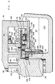
- Co-rotational scroll apparatus shown in Figure 1 as a scroll compressor assembly, is referred to by reference numeral 20.
- compressor assembly 20 is illustrated and described in terms of a hermetic scroll compressor but is interchangeably referred to as a scroll apparatus or assembly or compressor. It will be apparent to those skilled in the art that the subject invention is also applicable to scroll apparatus used as a fluid pump or expander and to scroll compressors not of the hermetic type.
- Compressor assembly 20 includes a hermetic shell 22 having an upper portion 24, a lower portion 26, a central shell portion 27 and an intermediate, central frame portion 28 affixed within the central shell 27.
- Central frame portion 28 separates high and low pressure regions within shell 22 as will further be described.
- Central shell 27 is a generally cylindrical body while central frame portion 28 has a generally cylindrical or annular exterior portion 30 and a central portion 32.
- the annular exterior portion 30 of the central frame portion 28 is sized to fit sealingly within exterior shell 27 so that it can be mated thereto by press fit, welding, electromagnetic deformation or by other suitable means.
- central frame portion 28 Integral with central frame portion 28 is a generally cylindrical upper bearing housing 34 which is preferably coaxial with exterior portion 30.
- a drive shaft aperture 36 extends axially through the center of the upper bearing housing 34 and an upper main bearing 38 is disposed therein.
- upper bearing 38 is a sleeve bearing made of sintered bronze or a similar material although it may be of a rolling element type.
- Electric motor 40 is disposed within central shell portion 27 of shell 22 and is comprised of a stator 42 which is disposed about a rotor 44.
- An annular space defined therebetween permits free rotation of the rotor 44 as well as the flow of fluid, such as refrigerant gas in which lubricant is entrained, therethrough and around.
- Stator 42 may be affixed within the exterior shell 27 by press fit, bolts (not shown), weldments (not shown) or by other means.
- An aperture 50 is defined in the upper portion of shell 22 for discharging compressed gas from the apparatus and an aperture 52 is defined in the lower portion of the shell for receiving suction pressure gas into the apparatus. This permits connection of compressor 20 to the refrigeration system schematically represented in Figure 2.
- the system of Figure 2 includes a discharge line 54 connected between discharge aperture 50 of compressor 20 and a condenser 60 as well as a line 62 which connects condenser 60 to an expansion device 64.
- the expansion device may be thermally or electrically actuated or may be comprised of one or more capillary tubes.
- An additional line 66 connects expansion device 64 to evaporator 68 where heat is transferred from a refrigeration load to the refrigerant within the system.
- a suction line 70 transfers refrigerant gas, which has been heated by the refrigeration load and which is at a suction pressure, from the evaporator 68 to the compressor 20. It will be apparent to those skilled in the art that it is contemplated that the refrigeration or air conditioning system of Figure 2 may include multiple units of the compressor assembly 20 as well as multiple condensers or evaporators and/or other components.
- scroll compressor assembly 20 includes a drive scroll member 76 and an idler scroll member 78.
- the first or drive scroll member 76 has an involute wrap 80 which is integral with and extends from surface 81 of generally planar end plate 82.
- An integral drive shaft 84 extends from end plate 82 in a direction opposite that from which scroll wrap 80 extends.
- a discharge gallery 86 is defined by a bore extending through drive shaft 84 and is in flow communication with a discharge port 88 defined by end plate 82.
- Drive shaft 84 preferably includes a first, relatively larger diameter bearing portion 90, carried in upper main bearing 38, and a second relatively smaller diameter rotor portion 92 fixedly disposed in motor rotor 44.
- the second or idler scroll member 78 has an upstanding involute wrap 100 which extends from surface 101 of idler scroll end plate 102 and which is in interleaving engagement with involute wrap 80 of the drive scroll member.
- Idler scroll member 78 also has a stub shaft 104 which extends from end plate 102 in a direction opposite that from which involute wrap 100 extends.
- An annular bearing 110 which may be a sleeve bearing or a bearing of the rolling element type, is disposed within a lower bearing housing 112.
- Lower bearing housing 112 which may be integral with shell portion 26 or formed in a separate component, rotatably supports idler scroll member 78.
- Drive scroll end plate 82 in the preferred embodiment, has two members 120 extending from it in the same direction and parallel to scroll wrap 80. Extension members 120 are disposed at radially opposed positions near the outer periphery of drive scroll end plate 82 and are of a length such that they extend past interleaved scroll wraps 80 and 100 as well as idler scroll end plate 102.
- Extension members 120 are affixed to a pressure plate 150 and provide one of several contemplated means for permitting the drive scroll member to rotatably carry the pressure plate member. Extension members 120 may be accommodated in a peripheral recess in pressure plate 150 and may be attached thereto by conventional means. It will be recognized that in the alternative, extension members 120 may be integral with pressure plate 150 and be fixedly attached to drive scroll end plate 82 as will be described with respect to Figures 8 and 9.
- pressure plate 150 will preferably be carried by the drive scroll member, it is contemplated that plate 150 can be driven other than by or through the drive scroll member. In that regard, it is contemplated and within the scope of the present invention that a separate power transmission mechanism be disposed in compressor 20 through which pressure plate 150 is rotatably driven. It is also contemplated that pressure plate 150 could be carried by the idler scroll member for pressure biasing interaction with the end plate of the drive scroll member.
- pressure plate 150 is an annular member fixedly attached to drive scroll member 76.
- Plate 150 is disposed adjacent to, but spaced apart from, idler scroll end plate 102 and presents a flat pressure responsive surface 151 to undersurface 152 of the idler scroll member.
- Pressure plate 150 also defines a central aperture 158 which is of greater diameter than lower bearing housing 112 thereby permitting the pressure plate to rotate freely about the bearing housing.
- An annular thrust bearing 160 may be disposed on shoulder 162 of the idler bearing housing 112 for supporting the weight of the scroll members 76 and 78 as well as that of drive shaft 84 and rotor 44 when the compressor is at rest and, to a lesser extent, when it is in operation.
- a high pressure lubricant sump 180 is provided above central portion 32 of frame 28.
- discharge pressure lubricant laden refrigerant is discharged from the scroll set through gallery 86 into the discharge pressure portion of shell 22 where the lubricant is disentrained from the refrigeration gas and falls into sump 180.
- the lubricant therein like the remainder of the interior of shell 22 located above frame 28, is at discharge pressure when the compressor is in operation.
- bore 184 provides flow communication through frame 28 for discharge pressure lubricant to flow from sump 180 to lubricant feed tube 186 and thence, through passage 188 of bearing housing 112 and volume 189 beneath idler scroll stub shaft 104, to bearing 110.
- tube 186 can be integrally cast into frame 28 and lower shell portion 26 or into a separate lower bearing housing if one is employed and that it need not be defined by a separate tubular member.
- upper bearing 38 and lower bearing 110 are sized with respect to their housings 34 and 112 and the scroll member shafts which rotate within them so that the flow of lubricant into the suction pressure portion SP of shell 22, after it has passed through and out of the respective upper and lower main bearings due to the pressure differential across them, is controlled in quantity.
- one or more lubricant passages 200 extend radially outward in the idler scroll end plate 102.
- a lubricant passage outlet 202 permits lubricant to flow from passage 200 to radially outermost first compression chamber 204 formed by the radially outer end portions 206 and 208 of scroll wraps 80 and 100.
- An intermediate pressure compression chamber 205 is radially inward of chamber 204 with discharge chamber 207 being the radially innermost of the compression chambers.
- a descending branch passage 203 permits the flow of lubricant, in a metered quantity, from lubricant passage 200 onto surface 151 of pressure plate 150 as will further be described.
- a first inlet 216 to lubricant passage 200 may be provided at its radially inward end.
- Inlet 216 receives lubricant from a lubricant collection chamber 218 defined between the idler scroll end plate 102, stub shaft 104 and the thrust bearing 160.
- Inlet 216 thus comprises one means for delivering lubricant to lubricant passage 200. It will be remembered that oil delivered to bearing 110 is at discharge pressure and that the differential pressure across the bearing will drive oil from space 189 beneath the stub shaft to chamber 218. Such oil, after having passed through bearing 110 emerges into collection chamber 218 which is at suction pressure.
- centrifugal force generated by the rotation of the idler scroll as well the pressure differential across bearing 110 which will serve to continuously "feed” oil to collection chamber 218 urges lubricant radially outward within passage 200 and assists in its delivery to locations requiring lubrication.
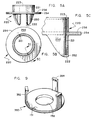
- a second inlet to lubricant passage 200 is through lubricant pickup member 220 which has an inlet 222 in the distal end of a bladelike portion that depends into lubricant sump 224 in the suction pressure portion SP of scroll apparatus 20. It is important to note that one or both of lubricant passage inlet 216 or inlet 222 of pickup member 220 may be employed in the delivery of lubricant to passage 200 and one or both may be referred to as inlets to lubricant passage 200.
- Plug 226 closes the radially outer end of the lubricant passage 200 which is drilled into the periphery of idler scroll end plate 102.
- the forces created by the fluid compression process which occurs within the compression chambers formed between the scroll members are forces that tend to push the scroll members axially apart and vary cyclically as the scroll members 76, 78 co-rotate.
- This cyclic variation of the separation forces is a function of the instantaneous location of the compression chambers during each revolution of the scroll members and the instantaneous pressure within those compression chambers which differs one from the other in the radial direction.
- annular pressure chamber 232 is defined in undersurface 152 of idler scroll end plate 102 by seal 230, radially inner wall 234, radially outer wall 236 and a wall 238 of the idler scroll member which joins the radially inner and outer walls 234 and 236.
- Both the inner wall 234 and the outer wall 236 are preferably perpendicular to undersurface 152 of the idler scroll member so that, together with the wall 238, they define a recess in undersurface 152 of the idler scroll member which is rectangular in cross section.
- At least one pressure fluid passage 240 is defined in idler scroll end plate 102 to permit the communication of pressure from one of the compression chambers C, defined between the scroll wraps of the drive and idler scroll members, to pressure chamber 232.
- a pressure intermediate suction and discharge pressure is communicated from intermediate pressure compression chamber 205 to pressure chamber 232.
- Seal 230 is preferably H-shaped in cross-section having a first leg 227 and a second leg 228 which are joined by a central span 229. As is taught in U.S. Patent 5,129,798, seal 230 may define an aperture 241 in span 229. Where seal 230 defines an aperture, it is characterized as a "vented" seal. Where span 229 is solid, as is illustrated and described with respect to Figure 6 as described below, seal 230 is characterized as an "unvented" seal.
- seal 230 It is preferable to form seal 230 from a somewhat flexible material so that the buildup of pressure within chamber 232 ensures fluid tight contact between seal 230 and walls 234 and 236. Seal 230 must also be in reasonably free sliding engagement with the respective inner and outer wall surfaces 234 and 236 of the idler scroll end plate while at the same time maintaining a skating but sealed interface between the idler scroll member and pressure plate 150.
- the energization of motor 40 causes the concurrent rotation of drive scroll member 76 and idler scroll member 78 through the operation of an Oldham coupling 242.
- the scroll wraps 80 and 100 form the series of compression chambers C in which suction pressure fluid, drawn from suction area SP, is compressed. A portion of such fluid, at an elevated pressure in one such pocket, is directed through pressure fluid passage 240 into chamber 232.
- the pressure in chamber 232 forces seal 230 into sealing engagement with planar surface 151 of pressure plate 150 which, in turn, causes the pressure fluid in chamber 232 to urge idler scroll 78 toward drive scroll member 76. In this manner the separation and tipping forces which are the result of the compression process occurring between the interleaved scroll members are counteracted and leakage between adjacent compression pockets across the tips of the scroll wraps is prevented or minimized.
- pickup member 220 picks up lubricant from lower sump 224.
- Lubricant flows through passage 221 into circumferential groove 223 of member 220 and thence into lubricant passage 200 which is in registry therewith through depending passage 225 in the idler scroll member.
- a portion of the lubricant flowing into and through passage 200 is discharged through outlet 202 in the upper surface of the idler scroll member thereby lubricating the interface between surface 101 of idler end plate 102 and the tip 244 of opposed scroll wrap 80.
- An additional portion of the lubricant is discharged from passage 200 through branch passage 203 onto surface 151 of pressure plate 150.
- seal 230 is urged firmly into engagement with planar surface 151 of compression plate 150 by the pressure in chamber 232.
- This engagement and the relative orbital motion of the surface 151 of compression plate 150 results in a need to lubricate the interface between seal 230 and pressure plate surface 151.
- branch passage 203 is located such that the lubricant passing through it is deposited onto surface 151 of the pressure plate radially inward of seal 230 and is sized to meter a predetermined quantity of lubricant onto the pressure plate surface.
- the centrifugal force generated by the rotation of the scroll member 76, to which plate 150 is affixed, causes the lubricant deposited on surface 151 to flow radially outward toward seal 230.
- Lubricant pickup member 220 will preferably be molded from an engineered material such as plastic and may have one or more depending blade members 250 in which inlets 222 and passages 221 are defined. Inlet 222 is preferably defined in a slanted surface 252 of blade 250 which facilitates the pickup and delivery of lubricant from sump 224.
- Pickup member 220 is pressed into a trepanned groove 231 in undersurface 152 of idler scroll member 78 and, by its nature and location, forms a barrier between the area radially external of thrust bearing 160 and pressure biasing seal 230.
- seal 230 in the embodiment of Figure 4, is of a vented design such that pressure chamber 232 is defined by the areas both above and below span 229. As such, the pressure assists in the balancing of forces on seal 230.
- leg portions 227 and 228 of seal 230 must themselves form a seal with respect to pressure responsive surface 151 of pressure plate 150 to prevent the leakage of pressure from pressure chamber 232 into suction pressure portion SP of the compressor shell.
- leg portions 227 and 228 of seal 230 and pressure responsive surface 151 are dynamic in that seal 230 moves with respect to pressure responsive surface 151 when the compressor is in operation. It is therefore particularly critical in the case of a vented seal to protect seal 230 and its leg portions from damage due to the deposit of debris onto surface 151 of pressure plate 150.
- lubricant pickup member 220 has an integral flange 254 which extends radially outward beyond the inner edge 159 of the aperture 158 of pressure plate 150.
- the upper planar surface 256 of flange 254 rotates in close proximity to undersurface 258 of pressure plate 150.
- unitary lubricant pickup member 220 in addition to providing for the delivery of lubricant to predetermined locations within compressor 20, acts to shield and protect surface 151 of pressure plate 150 and seal 230 from debris, such as particles of thrust bearing 160 or other debris which makes its way into lower sump 224, which might otherwise be splashed or carried onto surface 151 of pressure plate 150.
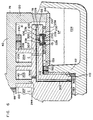
- a branch passage 300 descends from lubricant passage 200 in idler scroll member 78. Passage 300 also opens into pressure chamber 232 defined by the idler scroll member and annular seal 230. Lubricant is therefore utilized to actuate the pressure biasing arrangement of the compressor rather than gas.
- the pressure in chamber 232 can be controlled in a number of ways such as by venting of the chamber to a relatively lower pressure compressor location through a restricted passage (not shown).
- Lubricant passage 200 in the embodiment of Figure 6 is in flow communication, through passage 302, with volume 189 beneath idler scroll stub shaft 104. As will be recalled, the lubricant in volume 189 is at discharge pressure having been communicated thereto from discharge pressure sump 180.
- lubricant inlets 216 and 222 to lubricant passage 200 of the Figure 4 embodiment are eliminated in favor of inlet 302 in stub shaft 104. It is also to be noted that in the embodiment of Figure 6, the lubricant passage outlet 202 of Figure 4 is eliminated in favor of a radially innermore passage 304 which opens into intermediate pressure compression chamber 205.
- Discharge pressure lubricant in the embodiment of Figure 6 is communicated from area 189 through inlet 302 via a pressure reducing restriction 305, into lubricant passage 200.
- a portion of the lubricant makes its way through passage 304 into compression chamber 205 between the scroll members and onto the floor 306 of idler scroll member 78 to lubricate the interface between the tip 244 of involute 80 of the drive scroll member and the end plate 102 of the idler scroll member.
- the lubricant is also delivered from passage 200 into pressure chamber 232 where it acts as the medium which actuates the seal 230 of the pressure biasing arrangement of compressor 20.
- the lubricant flowing into passage 200 is directed both into pressure chamber 232, where it assists in the internal lubrication, cooling and sealing of the pressure biasing seal member, and into a compression chamber where it assists in the lubrication of the scroll elements and the cooling of gas undergoing compression.
- the need for the gas passage 240 by which pressure chamber 232 of the Figure 4 embodiment is pressurized, is eliminated.
- seal 230 is of the unvented type referred to above. That is, span 229 of seal 230 is solid and does not define an aperture. As such, pressure communicated into pressure chamber 232 resides only above span 229 of seal 230. The criticality of preventing damage to legs 227 and 228 from debris is therefore reduced since the dynamic interface between legs 227 and 228 and pressure responsive surface 151 is no longer one which must form a seal between pressure chamber 232 and the suction pressure portion SP of the compressor shell.
- lubricant pickup member 220 of the Figure 4 embodiment is dispensed with and inner edge 159 of aperture 158 is chamfered in a manner which assists in the lubrication of pressure responsive surface 151 of the pressure plate.
- chamfered surface 159 assists in the lubrication of seal 230 while still forming a protective barrier against the deposit of debris onto pressure responsive surface 151 with respect to debris which may make its way into sump 224.
- seal 230 acts as a barrier to the further radially outward movement of lubricant and since such lubricant is subjected to centrifugal forces by the rotation of the idler scroll member and pressure plate, a lubricant passage 307, shown in phantom in Figure 6, can be defined which penetrates end plate 102 of the idler scroll member. This permits the forced flow of such lubricant to the floor 306 of idler scroll member 78 for the purpose of lubricating the interface between the tip 244 of the involute wrap 80 of drive scroll member 76 and floor 306 of the idler scroll member.
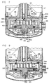
- lubricant feed tube 186 of the Figure 3 embodiment is disposed of in favor of an integral passage defined within the structure of compressor 20.
- the embodiment of Figure 7 also differs from embodiment of Figure 3 by its use of a discrete lower frame portion 400 which has an integral lower bearing housing 402.
- central shell 27 has radially spaced apart tabs 404 which engage the lower frame 400 so as to hold the central and lower frame portions in axial alignment and contact during the assembly process.
- Lip 409 of expanded portion 406 of the lower shell seats on an accommodating surface of lower frame 400 thereby positioning lower shell 26 for welding to central shall 27 which likewise facilitates the compressor assembly process.
- expanded portion 406 of lower shell 26 is welded to central shell 27 in a manner such that a circumferential space or passage 408 is partially defined by the shell at the radial periphery of the compressor.
- One or more suitably spaced bores 410 in central frame 28 then communicate between discharge pressure oil sump 180 and circumferential passage 408 intermediate adjacent ones of tabs 404 of shell 27.
- Circumferential passage 408 is, in turn, in flow communication with lubricant passage 412 which is integrally formed in lower frame portion 402 and which opens into space 189 beneath stub shaft 104 of the idler scroll member. It will be appreciated that the lubricant in space 189 acts on the end face of stub shaft 104 to pressure bias the idler scroll member 78 towards the drive scroll member 76.
- circumferential passage 408 is filled with discharge pressure lubricant when the compressor is in operation, a high to low side fluid seal is created between the frame and shell portions of the compressor which further prevents the leakage of discharge pressure gas from the discharge pressure portion of the shell to the suction pressure portion of the shell.
- This arrangement is advantageous as compared to other arrangements where the compressor frame and shell portion interface might otherwise be less of a barrier to the leakage of gas from the discharge to the suction pressure portions of the compressor.
- Pump 413 will preferably be any one of many types of positive displacement pumps typically used in such applications. It is to be noted that it would also be possible for pump 413 to be a pump of other than the positive displacement type such as a pump which employs centrifugal force to deliver oil to the required location such as through passage 415 to lower bearing 110.
- pressure plate surface 151 is lubricated in a manner similar to that discussed with respect to Figure 6 where lubricant impacting a chamfered pressure plate surface is deflected onto the pressure responsive surface of the pressure plate.
- discharge pressure lubricant from sump 180 is directed through passage 412 into area 189 and thence through passage 415 solely for the purpose of lubricating lower main bearing 110.
- Discharge pressure lubricant is not therefore, in the embodiment of Figure 7, employed for the purpose of lubricating the interface between idler end plate 102 and the tip 244 of opposed scroll wrap 80. It is contemplated, however, and must be understood, that the discharge pressure lubricant from sump 180 could be used with respect to Figure 7, in much the same manner as is suggested in the Figures 1-6 embodiments.
- lubricant is made available both to Oldham coupling 242 and at the interface of drive scroll end plate surface 81 with tip 422 of involute wrap 100 of the idler scroll member.
- a pump 300 of the centrifugal or positive displacement type is driven by idler scroll member 78 in a manner which causes oil to be pumped from low pressure sump 224 into volume 189 and thence through passage 415 to lubricate lower main bearing 110.
- the use of a positive displacement pump for lower main bearing lubrication purposes as is set forth above may be advantageous over a bearing lubrication arrangement which relies on a differential pressure, such as between suction and discharge pressure, to provide lubricant to the lower main bearing.
- Edge 359 of pressure plate 350 is inclined in a downward and radially outward direction so as to deflect lubricant flowing passed thrust bearing 160 downwardly and away from pressure responsive surface 151 of the pressure plate. As such, edge 359 of pressure plate 350 acts to shield pressure responsive surface 151 and legs 227 and 228 of vented seal 230 with respect to the deposit of debris onto the pressure responsive surface. Edge 359 therefore performs the protective function of lubricant pickup member 220 as has been described with respect to the embodiment of Figures 1, 3 and 4 above.
- Lip 504 in conjunction with recess 502 acts as an effective barrier to the migration of lubricant radially outward on surface 416 of the drive scroll member and diverts essentially all of the lubricant which flows from sump 180 through passage 182 past upper bearing 38 into groove 414 in surface 416 of the drive scroll member.
- the use of such lubricant in the lubrication of the interface between the tip 246 of the scroll wrap of the idler scroll member with surface 81 of the drive scroll member and in the lubrication of the Oldham coupling 242 is thereby maximized.
- FIG. 8 and 9 an alternative pressure plate arrangement to the arrangement of Figures 1, 3, 4, 6 and 7 is illustrated.
- the integral extension members 120 extending from idler scroll end plate 82 in the embodiments of Figures 1, 3, 4 and 6 are dispensed with in favor of a unitary pressure plate member 350 from which a plurality of legs 352 extend.
- Unitary pressure plate 350 like pressure plate 150 of the earlier embodiments, defines a pressure responsive surface 151 and aperture 158.
- Legs 352 of unitary pressure plate 350 act as integral spacers which define the distance between surface 81 of drive scroll end plate 82 and pressure surface 151. Legs 352 each include a mounting portion 354 which is accommodated in end plate 82 for attachment therewith. The attachment of unitary pressure plate member 350 to end plate 82 may be accomplished by mechanical fasteners such as screws 355 or by other means such as by welding, adhesion or the like.
- the drive scroll carries a pressure plate which allows for the axial biasing of the scroll members toward each other by means of a pressurized seal disposed between the idler scroll member and the pressure plate.
- the idler scroll member defines a passage through which lubricant is distributed.
- One or more branch passages provides for lubricant distribution within the compressor including one which deposits a metered quantity of lubricant onto the pressure plate radially inward of the seal of the pressure biasing arrangement. Centrifugal force, caused by the rotation of the pressure plate, urges the lubricant deposited on the pressure plate radially outward until it comes in contact with the seal. A portion of the lubricant is swept under the seal thereby lubricating the seal-to-pressure plate interface.
Landscapes
- Engineering & Computer Science (AREA)
- Mechanical Engineering (AREA)
- General Engineering & Computer Science (AREA)
- Rotary Pumps (AREA)
Applications Claiming Priority (3)
| Application Number | Priority Date | Filing Date | Title |
|---|---|---|---|
| US08/125,684 US5449279A (en) | 1993-09-22 | 1993-09-22 | Pressure biased co-rotational scroll apparatus with enhanced lubrication |
| US125684 | 1993-09-22 | ||
| PCT/US1994/009874 WO1995008713A1 (en) | 1993-09-22 | 1994-09-01 | Scroll apparatus with enhanced lubrication |
Publications (2)
| Publication Number | Publication Date |
|---|---|
| EP0721545A1 EP0721545A1 (en) | 1996-07-17 |
| EP0721545B1 true EP0721545B1 (en) | 2000-03-15 |
Family
ID=22420922
Family Applications (1)
| Application Number | Title | Priority Date | Filing Date |
|---|---|---|---|
| EP94927314A Expired - Lifetime EP0721545B1 (en) | 1993-09-22 | 1994-09-01 | Scroll apparatus with enhanced lubrication |
Country Status (8)
| Country | Link |
|---|---|
| US (4) | US5449279A (zh) |
| EP (1) | EP0721545B1 (zh) |
| JP (1) | JP3450009B2 (zh) |
| CN (1) | CN1119530C (zh) |
| AU (1) | AU7679794A (zh) |
| BR (1) | BR9407605A (zh) |
| CA (1) | CA2172396C (zh) |
| WO (1) | WO1995008713A1 (zh) |
Cited By (1)
| Publication number | Priority date | Publication date | Assignee | Title |
|---|---|---|---|---|
| DE112017004719B4 (de) | 2016-09-20 | 2023-06-01 | Lg Electronics Inc. | Gleichlaufender Spiralverdichter mit Gegendruckstruktur |
Families Citing this family (52)
| Publication number | Priority date | Publication date | Assignee | Title |
|---|---|---|---|---|
| JPH07259757A (ja) * | 1994-03-24 | 1995-10-09 | Sanyo Electric Co Ltd | 回転式スクロール圧縮機 |
| US5421709A (en) * | 1994-05-10 | 1995-06-06 | Alliance Compressors Inc. | Oil management in a high-side co-rotating scroll compressor |
| US5609478A (en) * | 1995-11-06 | 1997-03-11 | Alliance Compressors | Radial compliance mechanism for corotating scroll apparatus |
| JPH10339284A (ja) * | 1997-06-04 | 1998-12-22 | Denso Corp | スクロール型圧縮機 |
| US5989000A (en) * | 1997-08-07 | 1999-11-23 | Scroll Technologies | Scroll compressor with back pressure hole relief |
| US6074186A (en) * | 1997-10-27 | 2000-06-13 | Carrier Corporation | Lubrication systems for scroll compressors |
| US6171086B1 (en) * | 1997-11-03 | 2001-01-09 | Carrier Corporation | Scroll compressor with pressure equalization groove |
| US6015277A (en) * | 1997-11-13 | 2000-01-18 | Tecumseh Products Company | Fabrication method for semiconductor substrate |
| US6146118A (en) * | 1998-06-22 | 2000-11-14 | Tecumseh Products Company | Oldham coupling for a scroll compressor |
| US6149413A (en) * | 1998-07-13 | 2000-11-21 | Carrier Corporation | Scroll compressor with lubrication of seals in back pressure chamber |
| JP2000179460A (ja) * | 1998-12-15 | 2000-06-27 | Denso Corp | 圧縮機 |
| CN1270083C (zh) * | 1999-06-14 | 2006-08-16 | 松下冷机株式会社 | 密封式电机驱动压缩机 |
| US6224059B1 (en) * | 1999-07-16 | 2001-05-01 | Scroll Technologies | Controlled contact pressure for scroll compressor seal |
| US6280154B1 (en) | 2000-02-02 | 2001-08-28 | Copeland Corporation | Scroll compressor |
| US6217302B1 (en) * | 2000-02-24 | 2001-04-17 | Scroll Technologies | Floating seal bias for reverse fun protection in scroll compressor |
| JP4517444B2 (ja) * | 2000-03-31 | 2010-08-04 | 株式会社日立製作所 | スクロール圧縮機 |
| US6464480B2 (en) * | 2001-03-16 | 2002-10-15 | Scroll Technologies | Oil spout for scroll compressor |
| WO2005010373A1 (ja) * | 2003-07-09 | 2005-02-03 | Daikin Industries, Ltd. | 圧縮機 |
| KR100679886B1 (ko) * | 2004-10-06 | 2007-02-08 | 엘지전자 주식회사 | 급유 기능을 갖는 선회베인 압축기용 선회베인 |
| EP1830067B1 (en) * | 2004-12-22 | 2017-01-25 | Mitsubishi Denki Kabushiki Kaisha | Scroll compressor |
| US7371058B2 (en) * | 2005-03-30 | 2008-05-13 | Lg Electronics Inc. | Oil feeding propeller of scroll compressor |
| US10683865B2 (en) | 2006-02-14 | 2020-06-16 | Air Squared, Inc. | Scroll type device incorporating spinning or co-rotating scrolls |
| US7997883B2 (en) * | 2007-10-12 | 2011-08-16 | Emerson Climate Technologies, Inc. | Scroll compressor with scroll deflection compensation |
| US8152500B2 (en) * | 2008-01-17 | 2012-04-10 | Bitzer Scroll Inc. | Scroll compressor build assembly |
| KR101484538B1 (ko) * | 2008-10-15 | 2015-01-20 | 엘지전자 주식회사 | 스크롤 압축기 및 이를 적용한 냉동기기 |
| US11047389B2 (en) | 2010-04-16 | 2021-06-29 | Air Squared, Inc. | Multi-stage scroll vacuum pumps and related scroll devices |
| US20130232975A1 (en) | 2011-08-09 | 2013-09-12 | Robert W. Saffer | Compact energy cycle construction utilizing some combination of a scroll type expander, pump, and compressor for operating according to a rankine, an organic rankine, heat pump, or combined organic rankine and heat pump cycle |
| US9657737B2 (en) | 2013-07-31 | 2017-05-23 | Trane International Inc. | Scroll compressor with pressurized oil balance piston |
| US9765784B2 (en) | 2013-07-31 | 2017-09-19 | Trane International Inc. | Oldham coupling with enhanced key surface in a scroll compressor |
| TWM472176U (zh) * | 2013-11-07 | 2014-02-11 | Jia Huei Microsystem Refrigeration Co Ltd | 迴轉式壓縮機改良 |
| KR102243681B1 (ko) * | 2014-08-13 | 2021-04-23 | 엘지전자 주식회사 | 스크롤 압축기 |
| US10508543B2 (en) * | 2015-05-07 | 2019-12-17 | Air Squared, Inc. | Scroll device having a pressure plate |
| US10865793B2 (en) | 2016-12-06 | 2020-12-15 | Air Squared, Inc. | Scroll type device having liquid cooling through idler shafts |
| US10995754B2 (en) | 2017-02-06 | 2021-05-04 | Emerson Climate Technologies, Inc. | Co-rotating compressor |
| US11111921B2 (en) * | 2017-02-06 | 2021-09-07 | Emerson Climate Technologies, Inc. | Co-rotating compressor |
| US10215174B2 (en) | 2017-02-06 | 2019-02-26 | Emerson Climate Technologies, Inc. | Co-rotating compressor with multiple compression mechanisms |
| CN112119219B (zh) | 2018-05-04 | 2022-09-27 | 空气平方公司 | 固定和动涡旋压缩机、膨胀机或真空泵的液体冷却 |
| CN110617215A (zh) * | 2018-06-18 | 2019-12-27 | Lg电子株式会社 | 压缩机 |
| JP6648785B2 (ja) * | 2018-07-11 | 2020-02-14 | 株式会社富士通ゼネラル | 圧縮機 |
| US11067080B2 (en) | 2018-07-17 | 2021-07-20 | Air Squared, Inc. | Low cost scroll compressor or vacuum pump |
| US20200025199A1 (en) | 2018-07-17 | 2020-01-23 | Air Squared, Inc. | Dual drive co-rotating spinning scroll compressor or expander |
| US11530703B2 (en) | 2018-07-18 | 2022-12-20 | Air Squared, Inc. | Orbiting scroll device lubrication |
| WO2020050826A1 (en) * | 2018-09-05 | 2020-03-12 | Hitachi-Johnson Controls Air Conditioning, Inc. | Radial compliance in co-rotating scroll compressors |
| US11473572B2 (en) | 2019-06-25 | 2022-10-18 | Air Squared, Inc. | Aftercooler for cooling compressed working fluid |
| WO2021076143A1 (en) * | 2019-10-18 | 2021-04-22 | Hitachi-Johnson Controls Air Conditioning, Inc. | Stability in co-rotating scroll compressors |
| KR102668142B1 (ko) * | 2019-11-15 | 2024-05-23 | 코프랜드 엘피 | 동시 회전 스크롤 압축기 |
| KR102387691B1 (ko) * | 2020-08-20 | 2022-04-18 | 엘지전자 주식회사 | 스크롤 압축기 |
| US11898557B2 (en) | 2020-11-30 | 2024-02-13 | Air Squared, Inc. | Liquid cooling of a scroll type compressor with liquid supply through the crankshaft |
| EP4108924A1 (en) * | 2021-06-23 | 2022-12-28 | Emerson Climate Technologies GmbH | Thermal deformation management in a stationary scroll plate of a scroll compressor |
| US11885328B2 (en) | 2021-07-19 | 2024-01-30 | Air Squared, Inc. | Scroll device with an integrated cooling loop |
| US11732713B2 (en) | 2021-11-05 | 2023-08-22 | Emerson Climate Technologies, Inc. | Co-rotating scroll compressor having synchronization mechanism |
| US11624366B1 (en) | 2021-11-05 | 2023-04-11 | Emerson Climate Technologies, Inc. | Co-rotating scroll compressor having first and second Oldham couplings |
Family Cites Families (23)
| Publication number | Priority date | Publication date | Assignee | Title |
|---|---|---|---|---|
| US801182A (en) * | 1905-06-26 | 1905-10-03 | Leon Creux | Rotary engine. |
| DE1935621A1 (de) * | 1968-07-22 | 1970-01-29 | Leybold Heraeus Gmbh & Co Kg | Verdraengerpumpe |
| US4178143A (en) * | 1978-03-30 | 1979-12-11 | The United States Of America As Represented By The Secretary Of The Navy | Relative orbiting motion by synchronoously rotating scroll impellers |
| US4600369A (en) * | 1985-09-11 | 1986-07-15 | Sundstrand Corporation | Positive displacement scroll type apparatus with fluid pressure biasing the scroll |
| JPS62186084A (ja) * | 1986-02-12 | 1987-08-14 | Mitsubishi Electric Corp | スクロ−ル圧縮機 |
| JPS62210279A (ja) * | 1986-03-07 | 1987-09-16 | Mitsubishi Electric Corp | スクロ−ル圧縮機 |
| US4846640A (en) * | 1986-09-24 | 1989-07-11 | Mitsubishi Denki Kabushiki Kaisha | Scroll-type vacuum apparatus with rotating scrolls and discharge valve |
| US4927339A (en) * | 1988-10-14 | 1990-05-22 | American Standard Inc. | Rotating scroll apparatus with axially biased scroll members |
| JPH02271090A (ja) * | 1989-04-11 | 1990-11-06 | Mitsubishi Electric Corp | スクロール流体機械 |
| JPH0311183A (ja) * | 1989-06-09 | 1991-01-18 | Toshiba Corp | スクロール式圧縮機 |
| WO1991018207A1 (en) * | 1990-05-11 | 1991-11-28 | Sanyo Electric Co., Ltd. | Scroll compressor |
| JP2925674B2 (ja) * | 1990-07-16 | 1999-07-28 | 三洋電機株式会社 | スクロール圧縮機 |
| CA2049878C (en) * | 1990-10-29 | 1994-07-26 | Robert E. Utter | Scroll apparatus with enhanced lubricant flow |
| US5101644A (en) * | 1990-10-29 | 1992-04-07 | American Standard Inc. | Co-rotational scroll apparatus with positive lubricant flow |
| US5099658A (en) * | 1990-11-09 | 1992-03-31 | American Standard Inc. | Co-rotational scroll apparatus with optimized coupling |
| US5129798A (en) * | 1991-02-12 | 1992-07-14 | American Standard Inc. | Co-rotational scroll apparatus with improved scroll member biasing |
| US5142885A (en) * | 1991-04-19 | 1992-09-01 | American Standard Inc. | Method and apparatus for enhanced scroll stability in a co-rotational scroll |
| JPH05126073A (ja) * | 1991-11-05 | 1993-05-21 | Sanyo Electric Co Ltd | スクロール圧縮機 |
| US5199280A (en) * | 1991-11-25 | 1993-04-06 | American Standard Inc. | Co-rotational scroll compressor supercharger device |
| US5141417A (en) * | 1991-12-17 | 1992-08-25 | Carrier Corporation | Method for dynamically balancing nested coupling mechanisms for scroll machines |
| US5256042A (en) * | 1992-02-20 | 1993-10-26 | Arthur D. Little, Inc. | Bearing and lubrication system for a scroll fluid device |
| US5212964A (en) * | 1992-10-07 | 1993-05-25 | American Standard Inc. | Scroll apparatus with enhanced lubricant flow |
| JP2829718B2 (ja) * | 1995-10-27 | 1998-12-02 | 哲治 大柏 | 無段変速機を用いて制動エネルギを回収するアンチロックブレーキ |
-
1993
- 1993-09-22 US US08/125,684 patent/US5449279A/en not_active Expired - Lifetime
-
1994
- 1994-09-01 WO PCT/US1994/009874 patent/WO1995008713A1/en active IP Right Grant
- 1994-09-01 EP EP94927314A patent/EP0721545B1/en not_active Expired - Lifetime
- 1994-09-01 AU AU76797/94A patent/AU7679794A/en not_active Abandoned
- 1994-09-01 US US08/299,692 patent/US5462419A/en not_active Expired - Fee Related
- 1994-09-01 CN CN94194045A patent/CN1119530C/zh not_active Expired - Fee Related
- 1994-09-01 BR BR9407605A patent/BR9407605A/pt not_active IP Right Cessation
- 1994-09-01 JP JP50977995A patent/JP3450009B2/ja not_active Expired - Fee Related
- 1994-09-01 CA CA002172396A patent/CA2172396C/en not_active Expired - Fee Related
-
1995
- 1995-08-22 US US08/517,932 patent/US5616016A/en not_active Expired - Fee Related
-
1996
- 1996-12-19 US US08/770,604 patent/US5720602A/en not_active Expired - Fee Related
Cited By (1)
| Publication number | Priority date | Publication date | Assignee | Title |
|---|---|---|---|---|
| DE112017004719B4 (de) | 2016-09-20 | 2023-06-01 | Lg Electronics Inc. | Gleichlaufender Spiralverdichter mit Gegendruckstruktur |
Also Published As
| Publication number | Publication date |
|---|---|
| US5720602A (en) | 1998-02-24 |
| US5616016A (en) | 1997-04-01 |
| US5462419A (en) | 1995-10-31 |
| BR9407605A (pt) | 1997-01-14 |
| CN1119530C (zh) | 2003-08-27 |
| WO1995008713A1 (en) | 1995-03-30 |
| CA2172396A1 (en) | 1995-03-30 |
| AU7679794A (en) | 1995-04-10 |
| CN1134740A (zh) | 1996-10-30 |
| CA2172396C (en) | 2001-12-04 |
| EP0721545A1 (en) | 1996-07-17 |
| JPH09507547A (ja) | 1997-07-29 |
| JP3450009B2 (ja) | 2003-09-22 |
| US5449279A (en) | 1995-09-12 |
Similar Documents
| Publication | Publication Date | Title |
|---|---|---|
| EP0721545B1 (en) | Scroll apparatus with enhanced lubrication | |
| US4552518A (en) | Scroll machine with discharge passage through orbiting scroll plate and associated lubrication system | |
| US5421708A (en) | Oil separation and bearing lubrication in a high side co-rotating scroll compressor | |
| US4867657A (en) | Scroll compressor with axially balanced shaft | |
| EP0016532B1 (en) | Scroll-type fluid compressor unit | |
| EP0122469B1 (en) | Lubricating mechanism for scroll-type fluid displacement apparatus | |
| EP0972943B1 (en) | Scroll compressor with lubrification of seals in back pressure chamber | |
| US5931650A (en) | Hermetic electric scroll compressor having a lubricating passage in the orbiting scroll | |
| US6439867B1 (en) | Scroll compressor having a clearance for the oldham coupling | |
| EP0317270A2 (en) | Scroll compressor | |
| EP0118900B1 (en) | Lubricating mechanism for a scroll-type fluid displacement apparatus | |
| EP1630421B1 (en) | Lubricant pump of a compressor | |
| GB2154665A (en) | Scroll-type rotary compressor | |
| US7997883B2 (en) | Scroll compressor with scroll deflection compensation | |
| JPH01318780A (ja) | スクロール圧縮機 | |
| US6599110B2 (en) | Scroll-type compressor with lubricant provision | |
| US6179591B1 (en) | Conical hub bearing for scroll machine | |
| CA2356534C (en) | Scroll apparatus with enhanced lubrication | |
| US6015277A (en) | Fabrication method for semiconductor substrate | |
| JP2674113B2 (ja) | 横置形スクロール圧縮機 | |
| CA2005379A1 (en) | Hermetically sealed scroll type refrigerant compressor with a shaft seal mechanism | |
| JP2835059B2 (ja) | スクロール圧縮機 | |
| JPH06294385A (ja) | 回転式スクロール圧縮機 | |
| JPH0544664A (ja) | 横形スクロール圧縮機 | |
| JPS61112791A (ja) | スクロ−ル型圧縮機 |
Legal Events
| Date | Code | Title | Description |
|---|---|---|---|
| PUAI | Public reference made under article 153(3) epc to a published international application that has entered the european phase |
Free format text: ORIGINAL CODE: 0009012 |
|
| 17P | Request for examination filed |
Effective date: 19960419 |
|
| AK | Designated contracting states |
Kind code of ref document: A1 Designated state(s): FR GB |
|
| 17Q | First examination report despatched |
Effective date: 19980316 |
|
| GRAG | Despatch of communication of intention to grant |
Free format text: ORIGINAL CODE: EPIDOS AGRA |
|
| GRAG | Despatch of communication of intention to grant |
Free format text: ORIGINAL CODE: EPIDOS AGRA |
|
| GRAG | Despatch of communication of intention to grant |
Free format text: ORIGINAL CODE: EPIDOS AGRA |
|
| GRAH | Despatch of communication of intention to grant a patent |
Free format text: ORIGINAL CODE: EPIDOS IGRA |
|
| GRAH | Despatch of communication of intention to grant a patent |
Free format text: ORIGINAL CODE: EPIDOS IGRA |
|
| GRAA | (expected) grant |
Free format text: ORIGINAL CODE: 0009210 |
|
| AK | Designated contracting states |
Kind code of ref document: B1 Designated state(s): FR GB |
|
| ET | Fr: translation filed | ||
| PLBE | No opposition filed within time limit |
Free format text: ORIGINAL CODE: 0009261 |
|
| STAA | Information on the status of an ep patent application or granted ep patent |
Free format text: STATUS: NO OPPOSITION FILED WITHIN TIME LIMIT |
|
| 26N | No opposition filed | ||
| REG | Reference to a national code |
Ref country code: GB Ref legal event code: IF02 |
|
| PGFP | Annual fee paid to national office [announced via postgrant information from national office to epo] |
Ref country code: FR Payment date: 20080917 Year of fee payment: 15 |
|
| PGFP | Annual fee paid to national office [announced via postgrant information from national office to epo] |
Ref country code: GB Payment date: 20080929 Year of fee payment: 15 |
|
| GBPC | Gb: european patent ceased through non-payment of renewal fee |
Effective date: 20090901 |
|
| REG | Reference to a national code |
Ref country code: FR Ref legal event code: ST Effective date: 20100531 |
|
| PG25 | Lapsed in a contracting state [announced via postgrant information from national office to epo] |
Ref country code: FR Free format text: LAPSE BECAUSE OF NON-PAYMENT OF DUE FEES Effective date: 20090930 |
|
| PG25 | Lapsed in a contracting state [announced via postgrant information from national office to epo] |
Ref country code: GB Free format text: LAPSE BECAUSE OF NON-PAYMENT OF DUE FEES Effective date: 20090901 |