EP0718467B1 - Refroidissement de extrémité d'aube de turbine - Google Patents
Refroidissement de extrémité d'aube de turbine Download PDFInfo
- Publication number
- EP0718467B1 EP0718467B1 EP95308557A EP95308557A EP0718467B1 EP 0718467 B1 EP0718467 B1 EP 0718467B1 EP 95308557 A EP95308557 A EP 95308557A EP 95308557 A EP95308557 A EP 95308557A EP 0718467 B1 EP0718467 B1 EP 0718467B1
- Authority
- EP
- European Patent Office
- Prior art keywords
- tip
- airfoil
- notch
- leading edge
- trailing edge
- Prior art date
- Legal status (The legal status is an assumption and is not a legal conclusion. Google has not performed a legal analysis and makes no representation as to the accuracy of the status listed.)
- Expired - Lifetime
Links
Images

Classifications
-
- F—MECHANICAL ENGINEERING; LIGHTING; HEATING; WEAPONS; BLASTING
- F01—MACHINES OR ENGINES IN GENERAL; ENGINE PLANTS IN GENERAL; STEAM ENGINES
- F01D—NON-POSITIVE DISPLACEMENT MACHINES OR ENGINES, e.g. STEAM TURBINES
- F01D5/00—Blades; Blade-carrying members; Heating, heat-insulating, cooling or antivibration means on the blades or the members
- F01D5/12—Blades
- F01D5/14—Form or construction
- F01D5/20—Specially-shaped blade tips to seal space between tips and stator
-
- Y—GENERAL TAGGING OF NEW TECHNOLOGICAL DEVELOPMENTS; GENERAL TAGGING OF CROSS-SECTIONAL TECHNOLOGIES SPANNING OVER SEVERAL SECTIONS OF THE IPC; TECHNICAL SUBJECTS COVERED BY FORMER USPC CROSS-REFERENCE ART COLLECTIONS [XRACs] AND DIGESTS
- Y02—TECHNOLOGIES OR APPLICATIONS FOR MITIGATION OR ADAPTATION AGAINST CLIMATE CHANGE
- Y02T—CLIMATE CHANGE MITIGATION TECHNOLOGIES RELATED TO TRANSPORTATION
- Y02T50/00—Aeronautics or air transport
- Y02T50/60—Efficient propulsion technologies, e.g. for aircraft
Definitions
- the present invention relates generally to gas turbine engines, and, more specifically, to cooled turbine rotor blades thereof.
- a gas turbine engine such as that used for powering an aircraft in flight includes a combustor which generates hot combustion gases, with the discharge therefrom flowing through a high pressure turbine nozzle which directs the combustion gases to a row of turbine rotor blades which extract energy therefrom for rotating a disk and shaft joined thereto for typically powering a compressor of the engine.
- the first stage turbine rotor blades receive the hottest combustion gases in the engine and are therefore typically hollow and provided with various structures used for providing effective cooling thereof for ensuring useful operating lives therefor.
- the turbine rotor blades typically include serpentine flow passages therein and various cooling holes through the airfoil pressure side, suction side. or tip as required. Cooling air is provided to the blade by bleeding a portion of relatively cool compressor air and suitably channeling it through the blade dovetail and into the blade for supplying the cooling structures therein.
- any air bled from the compressor which is used for cooling purposes is not therefore used in the combustion process which necessarily decreases the overall efficiency of the engine. It is therefore desirable to use as little as possible of compressor bleed flow for cooling purposes.
- a gas turbine engine rotor blade comprising an airfoil and integral dovetail for mounting said airfoil to a rotor disk, said airfoil including:
- Figure 1 is a perspective, partly sectional view of an exemplary gas turbine engine rotor blade having an improved tip in accordance with one embodiment of the present invention
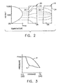
- Figure 2 is a schematic representation of an exemplary relative inlet temperature profile over pressure and suction sides of the blade illustrated in Figure 1;
- Figure 3 is an exemplary graph plotting static gas pressure at the tip of the blade illustrated in Figure 1 from the leading to trailing edges thereof and along the respective pressure and suction sides;
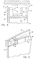
- Figure 4 is an elevational, partly sectional view of a portion of the tip of the blade illustrated in Figure 1 adjacent to a stationary shroud and taken generally along line 4-4, and illustrates a first notch in the blade tip for receiving a portion of the combustion gases flowable over the blade airfoil, and
- Figure 5 is a perspective view of the trailing edge of the blade illustrated in Figure 1 taken along line 5-5 illustrating in more detail a second notch in the blade tip for discharging gases from the tip cavity thereof.
- FIG. 1 Illustrated in Figure 1 is an exemplary gas turbine engine rotor blade 10 having a hollow airfoil 12 and an integral conventional dovetail 14 for mounting the airfoil 12 to a rotor disk (not shown) in a conventionally known manner.
- the blade 10 is representative of a first stage rotor blade disposed immediately downstream from a high pressure turbine nozzle (not shown) through which is channeled relatively hot combustion gas 16 generated in a conventional combustor (not shown).
- Internal cooling of turbine rotor blades is well known and typically utilizes a portion of relatively cool compressed air bled from a compressor of the gas turbine engine (not shown) which is suitably channeled through the respective dovetail 14 of several rotor blades 10 mounted around the perimeter of the rotor disk.
- the cooling fluid enters the airfoil 12 from the root 26 and passes therethrough for suitably cooling the airfoil 12 from the heating effect of the combustion gas 16 flowable over the outer surfaces thereof.
- the airfoil 12 may have pressure or suction side film cooling holes therethrough, or both (not shown) for conventionally cooling the sidewalls thereof, with the spent cooling fluid 32 being typically discharged in part from the airfoil 12 through a row of trailing edge holes 24a.
- the tip region or tip cap of the blade 10 typically includes a first squealer tip wall 34 which extends from adjacent the airfoil leading edge 22 along the airfoil first sidewall 18 to adjacent the trailing edge 24.
- the first tip wall 34 is typically integral with the airfoil first sidewall 18 and extends upwardly from the tip plate 28.
- a second squealer tip wall 36 extends from adjacent the leading edge 22 along the airfoil second sidewall 20 to adjacent the trailing edge 24 and is laterally spaced from the first tip wall 34 to define an open-top tip cavity 38 therebetween.
- the second tip wall 36 is typically integral with the airfoil second sidewall 20 and also extends upwardly from the tip plate 28.
- the first and second squealer tip walls 34, 36 are positioned closely adjacent to a conventional stationary stator shroud 40 during operation to define a suitable clearance therebetween, which clearance is preferably as small as possible for minimizing leakage of the combustion gas 16 therethrough as is conventionally known.
- the tip walls 34, 36 extend upwardly from the tip plate 28 so that in the event of rubbing between the walls 34, 36 and the inside surface of the shroud 40, only the tip walls 34, 36 are abraded, keeping intact the remainder of the airfoil 12 including the cooling chamber 30 therein.
- first and second tip walls 34, 36 are integral portions of the respective airfoil first and second sidewalls 18, 20, they form portions of the working surfaces which extract energy from the combustion gas 16 during operation, and therefore the two walls 34, 36 typically extend equally in height and are equally spaced from the shroud 40.
- the temperature patterns illustrated in Figure 2 are based on improved computational analysis conducted for explaining visual manifestations observed from used turbine rotor blades.
- the gas temperature pattern experienced by the airfoil 12 is typically center-peaked at the inlets or leading edges 22 of the several airfoils 12, secondary flow fields between circumferentially adjacent airfoils 12 distort the temperature profile substantially in the blade tip region on the pressure or second sidewall 20.
- the gas temperature at the pressure side tip region is substantially greater than the temperature on the suction side tip region, and increases with a substantial gradient primarily from the leading edge 22 to the mid-chord region upstream of the trailing edge 24 at the blade tip.
- the tip region of blades subject to this type of gas temperature pattern require suitable cooling thereof for ensuring a suitably long useful life of the blade 10 during operation.
- Figure 3 illustrates an exemplary static pressure distribution at the tip of the airfoil 12 between the leading edge 22 and trailing edge 24 thereof, with the pressure side profile being designated P and the suction side pressure profile being designated S.
- the static pressure along both the airfoil first sidewall 18 (S) and along the airfoil second sidewall 20 (P) are equal to each other and then diverge from each other with the pressure along the first, suction sidewall 18 being lower than the pressure along the pressure, second sidewall 20 up to about the region of the trailing edge 24.
- a first notch or slot 42 as shown generally in Figure 1 and in more detail in Figure 4, is disposed in one of the first and second tip walls 34, 36 adjacent to the airfoil leading edge 22 for channeling into the tip cavity 38 a portion 16a of the combustion gas 16 which flows over the airfoil 12.
- suitable driving pressure is required and may be obtained by locating the first notch 42 in the region of the maximum static pressure at the leading edge 22, which as shown in Figure 3 is in the region wherein the pressure and suction side pressures are generally equal.
- the first notch 42 is disposed in the airfoil first, or suction sidewall 18 closely adjacent to the leading edge 22. Since the pressure inside the tip cavity 38 downstream of the first notch 42 is necessarily lower than upstream of the first notch 42, a differential pressure will exist thereacross for channeling the gas portion 16a into the tip cavity 38.
- some of the combustion gas 16 necessarily passes over the blade tip in the clearance region below the shroud 40 from the pressure side to the suction side of the airfoil 12.
- the relatively cool combustion gas portion 16a By preferentially causing the relatively cool combustion gas portion 16a to flow through the tip cavity 38, penetration of the hotter combustion gas 16 flowing over the blade tip below the shroud 40 into the tip cavity 38 is reduced, with recirculation of such hotter combustion gas also being reduced inside the tip cavity 38.
- the temperature experienced by the blade tip from the combustion gas 16 may be effectively reduced by channeling into the tip cavity 38 the relatively cooler combustion gas portion 16a obtained adjacent to the leading edge 22, which when caused to flow through the tip cavity 38 decreases the recirculation of the hotter combustion gases therewith.
- a reduction in tip leakage of the combustion gas over the blade tip may also be obtained since the gas portion 16a provides an aerodynamic resistance to flow over the blade tip.
- Figure 3 illustrates that the static pressure adjacent the trailing edge 24 is relatively low and generally equal on both pressure and suction sides of the airfoil 12, and therefore the second notch 44 may be positioned in either the first or second squealer tip wall 34, 36. However, in the preferred embodiment illustrated in Figures 1 and 5, the second notch 44 is disposed in the first, or suction side, tip wall 34 as is the first notch 42.
- the first and second notches 42, 44 may take any suitable form for providing an inlet and outlet for the tip cavity 38 through its sidewalls 34, 36 and below the radially outer tip ends thereof.
- the first and second sidewalls 34,36 have respective heights h 1 and h 2 which are substantially equal for maximizing the surface area of the working suction and pressure sidewalls 18, 20 of the airfoil 12.
- the first notch 42 is generally rectangular in configuration and preferably extends partly into the first tip wall 34 from the top thereof with a depth d 1 measured downwardly toward the tip plate 28.
- the first notch 42 has a corresponding width w 1 so that the inlet flow area is adequate for channeling an effective amount of the gas portion 16a into the tip cavity 38.
- the entire first notch 42 is preferably positioned suitably adjacent to the airfoil leading edge 22 within the region of maximum static pressure shown by Figure 3. Since Figure 2 indicates that the gas temperature experienced by the blade 10 increases radially inwardly from the blade tip, the depth d 1 should not be excessive since the larger the depth d 1 , the greater the temperature of the gas portion 16a which will correspondingly decrease the temperature reducing effect thereof within the tip cavity 38.
- the first notch 42 extends suitably partly into the first tip wall 34 but above the tip plate 28 to obtain the lowest available combustion gas temperature. In alternate embodiments, the first notch 42 may extend completely to the tip plate 28 with d 1 being equal to h 1 .
- Figure 5 illustrates an exemplary embodiment of the second notch 44 which has a depth d 2 and extends completely into the first tip wall 34 to the top of the tip plate 28, with the depth d 2 being equal to the height h 1 of the first tip wall 34.
- the second tip wall 36 extends completely to the airfoil trailing edge 24, and the first tip wall 34 ends suitably short of the airfoil trailing edge 24, and is spaced laterally from the second tip wall 36 for defining the second notch 44 therebetween. In this way, the gas portion 16a after passing through the tip cavity 38 is discharged toward the trailing edge 24.
- the depth d 2 and the corresponding width w 2 of the second notch 44 are suitably selected for ensuring an effective crossflow of the gas portion 16a from the first notch 42 through the tip cavity 38 and out from the second notch 44.
- the second notch 44 may extend partly into the first tip wall 34 if desired.
- the combination of the first and second notches 42, 44 is effective for channeling into the tip cavity 38 the substantially cooler gas portion 16a available at the tip leading edge 22 which effectively reduces the resultant gas temperature in the tip cavity 38.
- the requirements for the cooling fluid 32 are therefore reduced for increasing engine efficiency.
- the tip leakage flow itself may also be reduced. Prolonged blade tip life and/or reduced tip cooling flow requirements from the invention improve the turbine performance.
Landscapes
- Engineering & Computer Science (AREA)
- Mechanical Engineering (AREA)
- General Engineering & Computer Science (AREA)
- Turbine Rotor Nozzle Sealing (AREA)
Claims (9)
- Aube (10) de rotor de turbine à gaz, comprenant un corps profilé (12) et une queue d'aronde (14) d'une seule pièce avec celui-ci pour le montage dudit corps profilé sur un disque de rotor, ledit corps profilé comportant:des parois latérales convexes (18) et concave (20) réunies l'une à l'autre au niveau d'un bord d'attaque (22) et au niveau d'un bord de fuite (24) et s'étendant depuis une emplanture (26) disposée sur ladite queue d'aronde, jusqu'à une plaque (28) d'extrémité, et une chambre de refroidissement (30) située dans ledit corps profilé pour recevoir un fluide de refroidissement via ladite queue d'aronde 14;une première paroi (34) d'extrémité sur ladite paroi latérale concave (20) du corps profilé, depuis ledit bord d'attaque (22) jusqu'au voisinage immédiat dudit bord de fuite (24), et espacée de ladite première paroi (34) d'extrémité pour définir entre elles une cavité (38) d'extrémité ouverte sur le dessus; et caractérisée parune première encoche (42) réalisée dans ladite première paroi (34) d'extrémité au voisinage immédiat dudit bord d'attaque (22) du corps profilé pour canaliser jusque dans ladite cavité d'extrémité une partie (16a) du gaz de combustion (16) pouvant passer sur ledit corps profilé (12).
- Aube selon la revendication 1, dans laquelle ledit corps profilé (12) est agencé pour réaliser une répartition de pression sur lesdites première (34) et seconde (36) parois d'extrémités depuis ledit bord d'attaque (22) jusqu'audit bord de fuite (24), et ladite première encoche (42) est située au voisinage immédiat dudit bord d'attaque (22) pour canaliser ladite partie (16a) du gaz à l'intérieur de ladite cavité (38) d'extrémité en raison de la différence de pression d'un côté à l'autre de ladite première encoche (42).
- Aube selon la revendication 1, comportant en outre une seconde encoche (44) ménagée dans l'une desdites première (34) et seconde (36) parois d'extrémités au voisinage immédiat dudit bord de fuite (24) du corps profilé pour refouler ladite partie (16a) du gaz depuis ladite cavité (38) d'extrémité et favoriser l'écoulement transversal de ladite partie 16a du gaz depuis ladite première encoche (42) jusqu'à ladite seconde encoche via ladite cavité d'extrémité.
- Aube selon la revendication 3, dans laquelle ladite première (42) et ladite seconde (44) encoches sont toutes deux réalisées dans ladite première paroi (34) d'extrémité du corps profilé.
- Aube selon la revendication 4, dans laquelle ladite paroi latérale convexe (18) du corps profilé (12) définit un côté aspiration dudit corps profilé, et ladite paroi latérale concave (20) définit un côté pression dudit corps profilé (12).
- Aube selon la revendication 5, dans laquelle ladite première (34) et ladite seconde (36) parois d'extrémités ont sensiblement la même hauteur.
- Aube selon la revendication 6, dans laquelle ladite première encoche (42) s'étend au moins partiellement dans ladite première paroi (34) d'extrémité, vers ladite plaque (28) d'extrémité.
- Aube selon la revendication 6, dans laquelle ladite seconde encoche (44) s'étend entièrement jusque dans ladite première paroi (34) d'extrémité jusqu'à ladite plaque (28) d'extrémité.
- Aube selon la revendication 6, dans laquelle ladite seconde paroi (36) d'extrémité s'étend entièrement jusqu'audit bord de fuite (24) du corps profilé, et ladite première paroi (36) d'extrémité se termine juste avant ledit bord de fuite (24) du corps profilé, et est espacée de ladite seconde paroi (36) d'extrémité pour définir entre elles ladite seconde encoche (44).
Applications Claiming Priority (2)
| Application Number | Priority Date | Filing Date | Title |
|---|---|---|---|
| US08/329,750 US5503527A (en) | 1994-12-19 | 1994-12-19 | Turbine blade having tip slot |
| US329750 | 2002-12-27 |
Publications (2)
| Publication Number | Publication Date |
|---|---|
| EP0718467A1 EP0718467A1 (fr) | 1996-06-26 |
| EP0718467B1 true EP0718467B1 (fr) | 2000-03-08 |
Family
ID=23286846
Family Applications (1)
| Application Number | Title | Priority Date | Filing Date |
|---|---|---|---|
| EP95308557A Expired - Lifetime EP0718467B1 (fr) | 1994-12-19 | 1995-11-28 | Refroidissement de extrémité d'aube de turbine |
Country Status (3)
| Country | Link |
|---|---|
| US (1) | US5503527A (fr) |
| EP (1) | EP0718467B1 (fr) |
| DE (1) | DE69515442T2 (fr) |
Families Citing this family (71)
| Publication number | Priority date | Publication date | Assignee | Title |
|---|---|---|---|---|
| GB9607578D0 (en) * | 1996-04-12 | 1996-06-12 | Rolls Royce Plc | Turbine rotor blades |
| US5927946A (en) * | 1997-09-29 | 1999-07-27 | General Electric Company | Turbine blade having recuperative trailing edge tip cooling |
| US5997251A (en) * | 1997-11-17 | 1999-12-07 | General Electric Company | Ribbed turbine blade tip |
| US6059530A (en) * | 1998-12-21 | 2000-05-09 | General Electric Company | Twin rib turbine blade |
| US6196792B1 (en) | 1999-01-29 | 2001-03-06 | General Electric Company | Preferentially cooled turbine shroud |
| US6179556B1 (en) * | 1999-06-01 | 2001-01-30 | General Electric Company | Turbine blade tip with offset squealer |
| US6174135B1 (en) * | 1999-06-30 | 2001-01-16 | General Electric Company | Turbine blade trailing edge cooling openings and slots |
| US6207295B1 (en) | 1999-07-13 | 2001-03-27 | General Electric Company | Article with tailorable high temperature coating |
| IT1319140B1 (it) * | 2000-11-28 | 2003-09-23 | Nuovo Pignone Spa | Sistema di refrigerazione per ugelli statorici di turbine a gas |
| US6422821B1 (en) | 2001-01-09 | 2002-07-23 | General Electric Company | Method and apparatus for reducing turbine blade tip temperatures |
| US6478537B2 (en) * | 2001-02-16 | 2002-11-12 | Siemens Westinghouse Power Corporation | Pre-segmented squealer tip for turbine blades |
| US6558119B2 (en) | 2001-05-29 | 2003-05-06 | General Electric Company | Turbine airfoil with separately formed tip and method for manufacture and repair thereof |
| US6599092B1 (en) | 2002-01-04 | 2003-07-29 | General Electric Company | Methods and apparatus for cooling gas turbine nozzles |
| US6602047B1 (en) | 2002-02-28 | 2003-08-05 | General Electric Company | Methods and apparatus for cooling gas turbine nozzles |
| US6932570B2 (en) * | 2002-05-23 | 2005-08-23 | General Electric Company | Methods and apparatus for extending gas turbine engine airfoils useful life |
| US6746209B2 (en) | 2002-05-31 | 2004-06-08 | General Electric Company | Methods and apparatus for cooling gas turbine engine nozzle assemblies |
| US6652235B1 (en) | 2002-05-31 | 2003-11-25 | General Electric Company | Method and apparatus for reducing turbine blade tip region temperatures |
| US6790005B2 (en) | 2002-12-30 | 2004-09-14 | General Electric Company | Compound tip notched blade |
| US6923616B2 (en) * | 2003-09-02 | 2005-08-02 | General Electric Company | Methods and apparatus for cooling gas turbine engine rotor assemblies |
| US7600972B2 (en) * | 2003-10-31 | 2009-10-13 | General Electric Company | Methods and apparatus for cooling gas turbine engine rotor assemblies |
| US6984112B2 (en) * | 2003-10-31 | 2006-01-10 | General Electric Company | Methods and apparatus for cooling gas turbine rotor blades |
| US7165940B2 (en) * | 2004-06-10 | 2007-01-23 | General Electric Company | Method and apparatus for cooling gas turbine rotor blades |
| US7118342B2 (en) * | 2004-09-09 | 2006-10-10 | General Electric Company | Fluted tip turbine blade |
| US7513743B2 (en) * | 2006-05-02 | 2009-04-07 | Siemens Energy, Inc. | Turbine blade with wavy squealer tip rail |
| US7600977B2 (en) * | 2006-05-08 | 2009-10-13 | General Electric Company | Turbine blade tip cap |
| US8500396B2 (en) * | 2006-08-21 | 2013-08-06 | General Electric Company | Cascade tip baffle airfoil |
| US8512003B2 (en) * | 2006-08-21 | 2013-08-20 | General Electric Company | Tip ramp turbine blade |
| US7607893B2 (en) | 2006-08-21 | 2009-10-27 | General Electric Company | Counter tip baffle airfoil |
| US8632311B2 (en) * | 2006-08-21 | 2014-01-21 | General Electric Company | Flared tip turbine blade |
| US7686578B2 (en) * | 2006-08-21 | 2010-03-30 | General Electric Company | Conformal tip baffle airfoil |
| US7597539B1 (en) | 2006-09-27 | 2009-10-06 | Florida Turbine Technologies, Inc. | Turbine blade with vortex cooled end tip rail |
| US8425183B2 (en) | 2006-11-20 | 2013-04-23 | General Electric Company | Triforial tip cavity airfoil |
| US20080317597A1 (en) * | 2007-06-25 | 2008-12-25 | General Electric Company | Domed tip cap and related method |
| US8011889B1 (en) * | 2007-09-07 | 2011-09-06 | Florida Turbine Technologies, Inc. | Turbine blade with trailing edge tip corner cooling |
| US7955053B1 (en) | 2007-09-21 | 2011-06-07 | Florida Turbine Technologies, Inc. | Turbine blade with serpentine cooling circuit |
| JP5029957B2 (ja) * | 2007-11-01 | 2012-09-19 | 株式会社Ihi | スキーラ付きタービン動翼 |
| US8016562B2 (en) * | 2007-11-20 | 2011-09-13 | Siemens Energy, Inc. | Turbine blade tip cooling system |
| US8206108B2 (en) * | 2007-12-10 | 2012-06-26 | Honeywell International Inc. | Turbine blades and methods of manufacturing |
| GB0724612D0 (en) * | 2007-12-19 | 2008-01-30 | Rolls Royce Plc | Rotor blades |
| FR2928405B1 (fr) * | 2008-03-05 | 2011-01-21 | Snecma | Refroidissement de l'extremite d'une aube. |
| GB0901129D0 (en) * | 2009-01-26 | 2009-03-11 | Rolls Royce Plc | Rotor blade |
| US8092179B2 (en) * | 2009-03-12 | 2012-01-10 | United Technologies Corporation | Blade tip cooling groove |
| EP2236746A1 (fr) | 2009-03-23 | 2010-10-06 | Alstom Technology Ltd | Turbine à gaz |
| US8157504B2 (en) * | 2009-04-17 | 2012-04-17 | General Electric Company | Rotor blades for turbine engines |
| US8186965B2 (en) * | 2009-05-27 | 2012-05-29 | General Electric Company | Recovery tip turbine blade |
| GB201006450D0 (en) * | 2010-04-19 | 2010-06-02 | Rolls Royce Plc | Blades |
| US8801377B1 (en) * | 2011-08-25 | 2014-08-12 | Florida Turbine Technologies, Inc. | Turbine blade with tip cooling and sealing |
| KR101324249B1 (ko) | 2011-12-06 | 2013-11-01 | 삼성테크윈 주식회사 | 스퀼러 팁이 형성된 블레이드를 구비한 터빈 임펠러 |
| US9260972B2 (en) * | 2012-07-03 | 2016-02-16 | United Technologies Corporation | Tip leakage flow directionality control |
| US9273561B2 (en) * | 2012-08-03 | 2016-03-01 | General Electric Company | Cooling structures for turbine rotor blade tips |
| EP2725194B1 (fr) | 2012-10-26 | 2020-02-19 | Rolls-Royce Deutschland Ltd & Co KG | Aube de rotor d'une turbine à gaz |
| DE102012021400A1 (de) * | 2012-10-31 | 2014-04-30 | Rolls-Royce Deutschland Ltd & Co Kg | Turbinenrotorschaufel einer Gasturbine |
| US8920124B2 (en) | 2013-02-14 | 2014-12-30 | Siemens Energy, Inc. | Turbine blade with contoured chamfered squealer tip |
| US9551226B2 (en) | 2013-10-23 | 2017-01-24 | General Electric Company | Turbine bucket with endwall contour and airfoil profile |
| US9638041B2 (en) | 2013-10-23 | 2017-05-02 | General Electric Company | Turbine bucket having non-axisymmetric base contour |
| US9528379B2 (en) | 2013-10-23 | 2016-12-27 | General Electric Company | Turbine bucket having serpentine core |
| US9797258B2 (en) * | 2013-10-23 | 2017-10-24 | General Electric Company | Turbine bucket including cooling passage with turn |
| US9670784B2 (en) | 2013-10-23 | 2017-06-06 | General Electric Company | Turbine bucket base having serpentine cooling passage with leading edge cooling |
| DE102013224998A1 (de) * | 2013-12-05 | 2015-06-11 | Rolls-Royce Deutschland Ltd & Co Kg | Turbinenrotorschaufel einer Gasturbine und Verfahren zur Kühlung einer Schaufelspitze einer Turbinenrotorschaufel einer Gasturbine |
| FR3021697B1 (fr) * | 2014-05-28 | 2021-09-17 | Snecma | Aube de turbine a refroidissement optimise |
| EP2960434A1 (fr) | 2014-06-25 | 2015-12-30 | Siemens Aktiengesellschaft | Profilé de compresseur et ensemble correspondant de rotor de compresseur |
| CN106471215B (zh) * | 2014-07-07 | 2018-06-19 | 西门子公司 | 燃气涡轮叶片凹槽状叶顶、对应的制造和冷却方法及燃气涡轮发动机 |
| FR3027951B1 (fr) * | 2014-11-04 | 2019-12-13 | Safran Aircraft Engines | Baignoire de sommet d'aubes d'une turbine de turbomachine |
| US10107108B2 (en) | 2015-04-29 | 2018-10-23 | General Electric Company | Rotor blade having a flared tip |
| US10329922B2 (en) | 2016-02-09 | 2019-06-25 | General Electric Company | Gas turbine engine airfoil |
| US10801331B2 (en) | 2016-06-07 | 2020-10-13 | Raytheon Technologies Corporation | Gas turbine engine rotor including squealer tip pocket |
| US10830082B2 (en) * | 2017-05-10 | 2020-11-10 | General Electric Company | Systems including rotor blade tips and circumferentially grooved shrouds |
| US10443405B2 (en) * | 2017-05-10 | 2019-10-15 | General Electric Company | Rotor blade tip |
| WO2019088992A1 (fr) | 2017-10-31 | 2019-05-09 | Siemens Aktiengesellschaft | Aube de turbine avec tranchée pointe |
| US11136890B1 (en) | 2020-03-25 | 2021-10-05 | General Electric Company | Cooling circuit for a turbomachine component |
| US11299991B2 (en) * | 2020-04-16 | 2022-04-12 | General Electric Company | Tip squealer configurations |
Family Cites Families (11)
| Publication number | Priority date | Publication date | Assignee | Title |
|---|---|---|---|---|
| US3635585A (en) * | 1969-12-23 | 1972-01-18 | Westinghouse Electric Corp | Gas-cooled turbine blade |
| DE2231426C3 (de) * | 1972-06-27 | 1974-11-28 | Motoren- Und Turbinen-Union Muenchen Gmbh, 8000 Muenchen | Deckbandlose, innen gekühlte Axialturbinenlaufschaufel |
| US4010531A (en) * | 1975-09-02 | 1977-03-08 | General Electric Company | Tip cap apparatus and method of installation |
| US4390320A (en) * | 1980-05-01 | 1983-06-28 | General Electric Company | Tip cap for a rotor blade and method of replacement |
| US4424001A (en) * | 1981-12-04 | 1984-01-03 | Westinghouse Electric Corp. | Tip structure for cooled turbine rotor blade |
| US4761116A (en) * | 1987-05-11 | 1988-08-02 | General Electric Company | Turbine blade with tip vent |
| FR2623569A1 (fr) * | 1987-11-19 | 1989-05-26 | Snecma | Aube de compresseur a lechettes d'extremite dissymetriques |
| US5183385A (en) * | 1990-11-19 | 1993-02-02 | General Electric Company | Turbine blade squealer tip having air cooling holes contiguous with tip interior wall surface |
| US5176499A (en) * | 1991-06-24 | 1993-01-05 | General Electric Company | Photoetched cooling slots for diffusion bonded airfoils |
| US5246340A (en) * | 1991-11-19 | 1993-09-21 | Allied-Signal Inc. | Internally cooled airfoil |
| US5403158A (en) * | 1993-12-23 | 1995-04-04 | United Technologies Corporation | Aerodynamic tip sealing for rotor blades |
-
1994
- 1994-12-19 US US08/329,750 patent/US5503527A/en not_active Expired - Lifetime
-
1995
- 1995-11-28 DE DE69515442T patent/DE69515442T2/de not_active Expired - Lifetime
- 1995-11-28 EP EP95308557A patent/EP0718467B1/fr not_active Expired - Lifetime
Also Published As
| Publication number | Publication date |
|---|---|
| EP0718467A1 (fr) | 1996-06-26 |
| DE69515442D1 (de) | 2000-04-13 |
| US5503527A (en) | 1996-04-02 |
| DE69515442T2 (de) | 2000-10-26 |
Similar Documents
| Publication | Publication Date | Title |
|---|---|---|
| EP0718467B1 (fr) | Refroidissement de extrémité d'aube de turbine | |
| EP1013878B1 (fr) | Aube de turbine avec double aillette terminale | |
| EP0716217B1 (fr) | Fentes déchargeuses d'air de bord de fuite d'aube de turbine refroidi par film d'air | |
| JP3844324B2 (ja) | ガスタービンエンジンタービンブレード用スクイーラ及びガスタービンエンジンタービンブレード | |
| US5261789A (en) | Tip cooled blade | |
| EP1024251B1 (fr) | Virole de turbine refroidie | |
| JP4486216B2 (ja) | 翼形部の隔離前縁冷却 | |
| EP1001137B1 (fr) | Aube de turbine à gaz à circuits de refroidissement en serpentin | |
| EP1445424B1 (fr) | Aube creuse avec circuit incorporé pour le refroidissement des extrémités | |
| CA2771349C (fr) | Aube de turbine a plateau de forme double | |
| US6607355B2 (en) | Turbine airfoil with enhanced heat transfer | |
| EP0954679B1 (fr) | Aube pouvant etre refroidie pour moteur a turbine a gaz | |
| US5700132A (en) | Turbine blade having opposing wall turbulators | |
| JP4546760B2 (ja) | 一体化されたブリッジを備えたタービンブレード | |
| EP1008724B1 (fr) | Aube de moteur à turbine à gaz | |
| US6220817B1 (en) | AFT flowing multi-tier airfoil cooling circuit | |
| EP1367222A2 (fr) | Méthode et dispositif de réduction de la température des extrémités des aubes | |
| US5695322A (en) | Turbine blade having restart turbulators | |
| EP1001135A2 (fr) | Aube de turbomachine refroidie par impact en cascade | |
| EP1057972A2 (fr) | Joint d'extrémité d'aube de turbine décalé | |
| EP1001136B1 (fr) | Aube pour turbomachine avec refroidissement séparé du bord d'attaque | |
| EP1544411A2 (fr) | Aube de turbomachine amortie en vibration avec une rangée de protubérances | |
| JPH07305603A (ja) | ガスタービンエンジンの空冷式翼型構造 | |
| GB2279705A (en) | Cooling of turbine blades of a gas turbine engine |
Legal Events
| Date | Code | Title | Description |
|---|---|---|---|
| PUAI | Public reference made under article 153(3) epc to a published international application that has entered the european phase |
Free format text: ORIGINAL CODE: 0009012 |
|
| AK | Designated contracting states |
Kind code of ref document: A1 Designated state(s): DE FR GB |
|
| 17P | Request for examination filed |
Effective date: 19961227 |
|
| 17Q | First examination report despatched |
Effective date: 19980107 |
|
| GRAG | Despatch of communication of intention to grant |
Free format text: ORIGINAL CODE: EPIDOS AGRA |
|
| GRAG | Despatch of communication of intention to grant |
Free format text: ORIGINAL CODE: EPIDOS AGRA |
|
| GRAH | Despatch of communication of intention to grant a patent |
Free format text: ORIGINAL CODE: EPIDOS IGRA |
|
| GRAH | Despatch of communication of intention to grant a patent |
Free format text: ORIGINAL CODE: EPIDOS IGRA |
|
| GRAA | (expected) grant |
Free format text: ORIGINAL CODE: 0009210 |
|
| AK | Designated contracting states |
Kind code of ref document: B1 Designated state(s): DE FR GB |
|
| ET | Fr: translation filed | ||
| REF | Corresponds to: |
Ref document number: 69515442 Country of ref document: DE Date of ref document: 20000413 |
|
| PLBE | No opposition filed within time limit |
Free format text: ORIGINAL CODE: 0009261 |
|
| STAA | Information on the status of an ep patent application or granted ep patent |
Free format text: STATUS: NO OPPOSITION FILED WITHIN TIME LIMIT |
|
| 26N | No opposition filed | ||
| REG | Reference to a national code |
Ref country code: GB Ref legal event code: IF02 |
|
| PGFP | Annual fee paid to national office [announced via postgrant information from national office to epo] |
Ref country code: DE Payment date: 20091127 Year of fee payment: 15 |
|
| PGFP | Annual fee paid to national office [announced via postgrant information from national office to epo] |
Ref country code: GB Payment date: 20091125 Year of fee payment: 15 Ref country code: FR Payment date: 20091201 Year of fee payment: 15 |
|
| GBPC | Gb: european patent ceased through non-payment of renewal fee |
Effective date: 20101128 |
|
| REG | Reference to a national code |
Ref country code: FR Ref legal event code: ST Effective date: 20110801 |
|
| REG | Reference to a national code |
Ref country code: DE Ref legal event code: R119 Ref document number: 69515442 Country of ref document: DE Effective date: 20110601 Ref country code: DE Ref legal event code: R119 Ref document number: 69515442 Country of ref document: DE Effective date: 20110531 |
|
| PG25 | Lapsed in a contracting state [announced via postgrant information from national office to epo] |
Ref country code: DE Free format text: LAPSE BECAUSE OF NON-PAYMENT OF DUE FEES Effective date: 20110531 |
|
| PG25 | Lapsed in a contracting state [announced via postgrant information from national office to epo] |
Ref country code: FR Free format text: LAPSE BECAUSE OF NON-PAYMENT OF DUE FEES Effective date: 20101130 |
|
| PG25 | Lapsed in a contracting state [announced via postgrant information from national office to epo] |
Ref country code: GB Free format text: LAPSE BECAUSE OF NON-PAYMENT OF DUE FEES Effective date: 20101128 |