EP1445424B1 - Aube creuse avec circuit incorporé pour le refroidissement des extrémités - Google Patents
Aube creuse avec circuit incorporé pour le refroidissement des extrémités Download PDFInfo
- Publication number
- EP1445424B1 EP1445424B1 EP04250454A EP04250454A EP1445424B1 EP 1445424 B1 EP1445424 B1 EP 1445424B1 EP 04250454 A EP04250454 A EP 04250454A EP 04250454 A EP04250454 A EP 04250454A EP 1445424 B1 EP1445424 B1 EP 1445424B1
- Authority
- EP
- European Patent Office
- Prior art keywords
- tip
- micropassages
- cooling
- airfoil
- cooling air
- Prior art date
- Legal status (The legal status is an assumption and is not a legal conclusion. Google has not performed a legal analysis and makes no representation as to the accuracy of the status listed.)
- Expired - Lifetime
Links
- 238000001816 cooling Methods 0.000 title claims description 158
- 238000000034 method Methods 0.000 claims description 16
- 238000004891 communication Methods 0.000 claims description 14
- 229910052751 metal Inorganic materials 0.000 claims description 11
- 239000002184 metal Substances 0.000 claims description 11
- 230000007704 transition Effects 0.000 claims description 9
- 239000003870 refractory metal Substances 0.000 claims description 8
- PXHVJJICTQNCMI-UHFFFAOYSA-N Nickel Chemical compound [Ni] PXHVJJICTQNCMI-UHFFFAOYSA-N 0.000 claims description 6
- 238000005266 casting Methods 0.000 claims description 5
- 239000012809 cooling fluid Substances 0.000 claims description 4
- 229910045601 alloy Inorganic materials 0.000 claims description 3
- 239000000956 alloy Substances 0.000 claims description 3
- 229910052759 nickel Inorganic materials 0.000 claims description 3
- 229910000531 Co alloy Inorganic materials 0.000 claims description 2
- 241000219793 Trifolium Species 0.000 claims description 2
- NJPPVKZQTLUDBO-UHFFFAOYSA-N novaluron Chemical compound C1=C(Cl)C(OC(F)(F)C(OC(F)(F)F)F)=CC=C1NC(=O)NC(=O)C1=C(F)C=CC=C1F NJPPVKZQTLUDBO-UHFFFAOYSA-N 0.000 claims 8
- 238000013461 design Methods 0.000 description 25
- 239000007789 gas Substances 0.000 description 21
- 239000000567 combustion gas Substances 0.000 description 18
- 230000008901 benefit Effects 0.000 description 8
- 239000002826 coolant Substances 0.000 description 8
- 238000012546 transfer Methods 0.000 description 7
- 230000001965 increasing effect Effects 0.000 description 5
- 238000002156 mixing Methods 0.000 description 5
- 238000002485 combustion reaction Methods 0.000 description 4
- 238000010926 purge Methods 0.000 description 4
- 238000013459 approach Methods 0.000 description 3
- 230000000694 effects Effects 0.000 description 3
- 230000002708 enhancing effect Effects 0.000 description 3
- 239000000446 fuel Substances 0.000 description 3
- 230000008569 process Effects 0.000 description 3
- 230000009286 beneficial effect Effects 0.000 description 2
- 238000009413 insulation Methods 0.000 description 2
- 238000004519 manufacturing process Methods 0.000 description 2
- 239000000203 mixture Substances 0.000 description 2
- 238000010248 power generation Methods 0.000 description 2
- ZOKXTWBITQBERF-UHFFFAOYSA-N Molybdenum Chemical compound [Mo] ZOKXTWBITQBERF-UHFFFAOYSA-N 0.000 description 1
- 230000001133 acceleration Effects 0.000 description 1
- 238000005452 bending Methods 0.000 description 1
- 230000015572 biosynthetic process Effects 0.000 description 1
- 230000000740 bleeding effect Effects 0.000 description 1
- 230000015556 catabolic process Effects 0.000 description 1
- 239000000919 ceramic Substances 0.000 description 1
- 230000000295 complement effect Effects 0.000 description 1
- 230000007812 deficiency Effects 0.000 description 1
- 238000006731 degradation reaction Methods 0.000 description 1
- 238000009792 diffusion process Methods 0.000 description 1
- 238000005553 drilling Methods 0.000 description 1
- 239000012530 fluid Substances 0.000 description 1
- 239000011888 foil Substances 0.000 description 1
- 238000010438 heat treatment Methods 0.000 description 1
- 238000005495 investment casting Methods 0.000 description 1
- 238000003754 machining Methods 0.000 description 1
- 239000000463 material Substances 0.000 description 1
- 238000002844 melting Methods 0.000 description 1
- 230000008018 melting Effects 0.000 description 1
- 150000002739 metals Chemical group 0.000 description 1
- 238000012986 modification Methods 0.000 description 1
- 230000004048 modification Effects 0.000 description 1
- 229910052750 molybdenum Inorganic materials 0.000 description 1
- 239000011733 molybdenum Substances 0.000 description 1
- 230000003647 oxidation Effects 0.000 description 1
- 238000007254 oxidation reaction Methods 0.000 description 1
- 230000003071 parasitic effect Effects 0.000 description 1
- 230000004044 response Effects 0.000 description 1
- 238000005096 rolling process Methods 0.000 description 1
- 230000003068 static effect Effects 0.000 description 1
- 239000000126 substance Substances 0.000 description 1
- 229910000601 superalloy Inorganic materials 0.000 description 1
- WFKWXMTUELFFGS-UHFFFAOYSA-N tungsten Chemical compound [W] WFKWXMTUELFFGS-UHFFFAOYSA-N 0.000 description 1
- 229910052721 tungsten Inorganic materials 0.000 description 1
- 239000010937 tungsten Substances 0.000 description 1
- 238000004018 waxing Methods 0.000 description 1
Images


Classifications
-
- F—MECHANICAL ENGINEERING; LIGHTING; HEATING; WEAPONS; BLASTING
- F01—MACHINES OR ENGINES IN GENERAL; ENGINE PLANTS IN GENERAL; STEAM ENGINES
- F01D—NON-POSITIVE DISPLACEMENT MACHINES OR ENGINES, e.g. STEAM TURBINES
- F01D5/00—Blades; Blade-carrying members; Heating, heat-insulating, cooling or antivibration means on the blades or the members
- F01D5/12—Blades
- F01D5/14—Form or construction
- F01D5/20—Specially-shaped blade tips to seal space between tips and stator
-
- F—MECHANICAL ENGINEERING; LIGHTING; HEATING; WEAPONS; BLASTING
- F01—MACHINES OR ENGINES IN GENERAL; ENGINE PLANTS IN GENERAL; STEAM ENGINES
- F01D—NON-POSITIVE DISPLACEMENT MACHINES OR ENGINES, e.g. STEAM TURBINES
- F01D5/00—Blades; Blade-carrying members; Heating, heat-insulating, cooling or antivibration means on the blades or the members
- F01D5/02—Blade-carrying members, e.g. rotors
- F01D5/08—Heating, heat-insulating or cooling means
-
- F—MECHANICAL ENGINEERING; LIGHTING; HEATING; WEAPONS; BLASTING
- F01—MACHINES OR ENGINES IN GENERAL; ENGINE PLANTS IN GENERAL; STEAM ENGINES
- F01D—NON-POSITIVE DISPLACEMENT MACHINES OR ENGINES, e.g. STEAM TURBINES
- F01D5/00—Blades; Blade-carrying members; Heating, heat-insulating, cooling or antivibration means on the blades or the members
- F01D5/12—Blades
- F01D5/14—Form or construction
- F01D5/18—Hollow blades, i.e. blades with cooling or heating channels or cavities; Heating, heat-insulating or cooling means on blades
- F01D5/187—Convection cooling
-
- F—MECHANICAL ENGINEERING; LIGHTING; HEATING; WEAPONS; BLASTING
- F05—INDEXING SCHEMES RELATING TO ENGINES OR PUMPS IN VARIOUS SUBCLASSES OF CLASSES F01-F04
- F05D—INDEXING SCHEME FOR ASPECTS RELATING TO NON-POSITIVE-DISPLACEMENT MACHINES OR ENGINES, GAS-TURBINES OR JET-PROPULSION PLANTS
- F05D2260/00—Function
- F05D2260/20—Heat transfer, e.g. cooling
- F05D2260/221—Improvement of heat transfer
- F05D2260/2212—Improvement of heat transfer by creating turbulence
-
- Y—GENERAL TAGGING OF NEW TECHNOLOGICAL DEVELOPMENTS; GENERAL TAGGING OF CROSS-SECTIONAL TECHNOLOGIES SPANNING OVER SEVERAL SECTIONS OF THE IPC; TECHNICAL SUBJECTS COVERED BY FORMER USPC CROSS-REFERENCE ART COLLECTIONS [XRACs] AND DIGESTS
- Y02—TECHNOLOGIES OR APPLICATIONS FOR MITIGATION OR ADAPTATION AGAINST CLIMATE CHANGE
- Y02T—CLIMATE CHANGE MITIGATION TECHNOLOGIES RELATED TO TRANSPORTATION
- Y02T50/00—Aeronautics or air transport
- Y02T50/60—Efficient propulsion technologies, e.g. for aircraft
Definitions
- This invention relates to coolable airfoils of the type used in high temperature rotary machines such as gas turbines and, more particularly, to an improved tip cooling scheme for airfoils.
- Prior art turbine blade cooling methods are disclosed in US 6,164,914 , EP 1063388 and GB 2,077,3b3.
- Efficiency is a primary concern in the design of any gas turbine engine. Historically, one of the principle techniques for increasing efficiency has been to increase the gas path temperatures within the engine. Using internally cooled components made from high temperature capacity alloys has accommodated the increased temperatures. Turbine stator vanes and blades, for example, are typically cooled using compressor air worked to a higher pressure, but still at a lower temperature than that of the core gas flow passing by the blade or the vane. It will be understood that compressor bleed air for such cooling will be unavailable to support combustion in the combustor. The higher pressure provides the energy necessary to push the air through the component. A significant percentage of the work imparted to the air bled from the compressor, however, is lost during the cooling process.
- Airfoil cooling is accomplished by external film cooling, internal air impingement and forced convection either separately or a combination of all cooling methods.
- compressor bleed air flows through the internal cavities of the blades and vanes, continuously removing heat therefrom.
- Compressor bleed air enters the cavities 38 through one or more inlets which discharges into the internal cavities.
- Film cooling has been shown to be very effective but requires a great deal of fluid flow to be bled off the compressor for cooling. Further, film cooling is actively controlled in a complex and expensive manner. Also, the fabrication and machining of an airfoil with film cooling holes adds a degree of complexity that is costly. It will also be appreciated that once the cooling air exits the internal cavity of the airfoil and mixes with the hot gases, a severe performance penalty is incurred due to the mixing process and the different temperature levels of the mixing flows. Thus, film cooling requires a greater amount of cooling air with the possibility of inadequate cooling of the outer surfaces of the airfoil.
- Prior art coolable airfoils typically include a plurality of internal cavities (cooling circuit), which are supplied with cooling air.
- the cooling air passes through the wall of the airfoil (or the platform) and transfers thermal energy away from the airfoil in the process.
- blade tip film cooling holes provide external film cooling issued on the blade tip pressure side in the radial and axial directions. Some designs use as many film holes as possible, in the limited space available, in an effort to flood the pressure side tip region with coolant. It is desired that this film cooling then carry over onto the outer tip surface to provide cooling there and also over the suction side surfaces of tip. Film holes are oriented in the radially outward direction because the prevailing mainstream gas flows tend to migrate in this manner in the tip region. In practice, it is still very difficult and very inconsistent to cool the blade tip in this manner due to the very complex nature of the cooling flow as it mixes with very dynamic hot gases of the mainstream flow.
- cooling flow exits the film holes and is swept by the hot combustion gases towards the trailing edge of the airfoil and away from tip cap.
- this results in a mixed effect, where some of the cooling air is caught up and mixed with the hot gases and some goes onto tip cap and some goes axially along the airfoil to trailing edge. This results in inadequate cooling of tip cap and eventual temperature inflicted degradation of tip cap.
- Turbine engine blade designers and engineers are constantly striving to develop more efficient ways of cooling the tips of the turbine blades to prolong turbine blade life and reduce engine operating cost. Cooling air used to accomplish this is expensive in terms of overall fuel consumption. Thus, more effective and efficient use of available cooling air in carrying out cooling of turbine blade tips is desirable not only to prolong turbine blade life but also to improve the efficiency of the engine as well, thereby again lowering engine operating cost. Consequently, there is a continuing need for a cooling design that will make more effective and efficient use of available cooling air.
- the present invention provides a hollow airfoil having a pressure sidewall and a suction sidewall, said pressure and suction sidewalls joined together at leading and trailing edges and extending from a root to a tip, characterised by the hollow airfoil having an embedded microcircuit in said tip, the embedded microcircuit comprising: at least one plenum disposed between said pressure and suction sidewalls; a plurality of inlets through which cooling air may enter, said plurality of inlets being proximate to said suction sidewall and in flow communication with said plenum; a plurality of interconnect micropassages in flow communication with said inlets and through which the cooling air may enter; a plurality of outlets in flow communication with said interconnect micropassages, said outlets are disposed within said pressure sidewall and transition the cooling air from said interconnect micropassages to a region exterior to the tip of the hollow airfoil, wherein said interconnect micropassages extend across said tip from said inlets to said outlets, and wherein said interconnect micropassages interconnect with each other
- the present invention can be implemented and utilized in connection with many alternative airfoil (blade and vane) configurations.
- the combination of a) effective convective cooling provided by the micropassages and b) effective thermal insulation on the tip surface due to film cooling provides a cooler tip, as compared to conventional and current designs.
- an airfoil tip employing the beneficial cooling design of the present invention will not only have a longer service life but also improve overall turbine efficiency.
- the present invention also provides a method for cooling a tip of a turbine blade suitable for use in a gas turbine, comprising the steps of fabricating an embedded microcircuit under a surface of the tip, said microcircuit comprising: an inlet to allow passage of cooling flow from a cooling fluid source within the turbine blade, said inlet being proximate to a suction sidewall; a plurality of interconnecting micropassages in flow communication with said inlet and through which cooling flow may enter; and an outlet in flow communication with said interconnecting micropassages, said outlet transitions the cooling flow from said interconnecting micropassages to a region exterior to the tip of the airfoil, wherein said interconnecting micropassages extend across said tip from said inlet to said outlet, and wherein said interconnecting micropassages interconnect with each other between said inlet and said outlet, said micropassages oriented to substantially traverse the tip between the suction sidewall and a pressure sidewall, the micropassages arranged to be fed said cooling flow from said inlet and to discharge the cooling flow through said
- a gas turbine engine 10 such as a gas turbine used for power generation or propulsion, circumferentially disposed about an engine centerline, or axial centerline axis 12 is shown.
- the engine 10 includes a fan 14, a compressor 16 ( Fig. 1 ), a combustion section 18 and a turbine 20.
- air compressed in the compressor 16 ( Fig. 1 ) is mixed with fuel which is burned in the combustion section 18 and expanded in turbine 20.
- the air compressed in the compressor 16 ( Fig. 1 ) and the fuel mixture expanded in the turbine 20 can both be referred to as a hot gas stream flow (hot combustion gases, gas flow) 28.
- the turbine 20 includes rotors 22 which, in response to the expansion, rotate driving the compressor 16 ( Fig. 1 ) and fan 14.
- the turbine 20 comprises alternating rows of rotary airfoils or blades 24 and static airfoils or vanes 26.
- the use of the system of FIG. 1 is for illustrative purposes only and is not a limitation of the instant invention which may be employed on gas turbines used for electrical power generation and aircraft.
- Each blade 24 has a dovetail 30 which retains the blade 24 in a complementary dovetail slot formed in the perimeter of a rotor disk 32 ( Fig. 1 ).
- a plurality of blade tip film cooling holes 34 is disposed within an outer end portion or tip 36 of the blade 24 and is fed by at least one internal cooling cavity (cavity) 38.
- the internal cavity is fed cooling air from the compressor 16 ( Fig. 1 ).
- the film cooling holes 34 provide external film cooling issued on the tip 36 in generally the radial direction.
- Some designs use as many film cooling holes as possible in an effort to flood the tip region with the cooling air to cool the tip 36. In practice, it is very difficult to achieve uniform cooling of the tip 36 due to the complex nature of the mixing of the cooling air ejected from the film holes with the hot combustion gases 28 traveling through the turbine 20 ( Fig. 1 ).
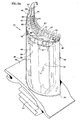
- Fig. 3A the blade tip cooling design of the present invention is shown.
- the present invention employs an embedded microcircuit 40 in the tip 36 of the blade 24 to provide convective and film cooling of the tip 36.
- the microcircuit 40 shown in Fig. 3A illustrates the flow path of the cooling air (cooling flow) 41 at it transitions through the microcircuit 40.
- FIG. 3B is a partial perspective view of the tip of the airfoil of FIG. 3A .
- FIG. 3C is an enlarged perspective view showing the tip of the airfoil of FIG. 3B .
- the blade 24 is cast and has a hollow airfoil 54 with the cavity 38 located therein.
- the blade 24 is disposed radially above the dovetail 30.
- the internal cavity 38 may be of any conventional form, multi-pass serpentine channels (cooling circuit), with the cooling air 41 typically being a portion of the air bled from the compressor 16 ( Fig. 1 ) of the engine, as described hereinabove.
- the airfoil 54 has a plurality of internal cooling cavities (cooling circuit) 38 that are connected to a source of cooling air, such as the compressor 16 ( Fig. 1 ).
- the blade 24 includes a generally concave, first or pressure sidewall 42 spaced laterally or circumferentially in most part from a convex, second or suction sidewall 44.
- the sidewalls 42, 44 are joined together at axially opposite leading and trailing edges 46, 48, respectively, and extend longitudinally or radially from a root 50 where the airfoil 54 meets an integral platform 56 to the tip 36 or tip portion that encloses the airfoil 54.
- the airfoil 54 has an external wall 58 which includes the suction sidewall 44 and pressure sidewall 42 disposed on opposing sides of a mean camber line 60.
- the sidewalls 42, 44 extend chordwise between the leading and trailing edges 46, 48, respectively, and spanwise between the platform and the tip.
- the external wall 58 includes an exterior surface 66, part of which is top surface (tip surface) 67.
- the hot combustion gases (gas flow) 28 flow across the exterior surface 66 of the airfoil 54.
- Microcircuits offer tailorable, high convective efficiency cooling. Along with high convective efficiency, high film effectiveness is required for an advanced cooling configuration.
- Fig. 3A illustrates the microcircuit 40 of the present invention located outboard of the cavities 38. Microcircuits may be machined or otherwise molded within a part. In a preferred embodiment, the microcircuits are formed of refractory metals forms and encapsulated in the part mold prior to casting. Several refractory metals including molybdenum (Mo) and Tungsten (W) have melting points that are in excess of typical casting temperatures of nickel based superalloys.
- Mo molybdenum
- W Tungsten
- refractory metals can be produced in wrought thin sheet or forms in sizes necessary to make cooling channels characteristic of those found in turbine and combustor cooling designs.
- microcircuits may be fabricated into parts including, but not limited to, combustor liners, turbine vanes, turbine blades, turbine shrouds, vane endwalls, and airfoil edges.
- such parts are formed in part or in whole of nickel based alloys or cobalt based alloys.
- Thin refractory metal sheets and foils possess enough ductility to allow bending and forming into complex shapes. The ductility yields a robust design capable of surviving a waxing/shelling cycle.
- the refractory metal can be removed, such as through chemical removal, thermal leeching, or oxidation methods, leaving behind a cavity forming the microcircuit 40 as shown in Fig. 3A .
- the cooling design of the present invention may also be manufactured using investment casting techniques with ceramic cores.
- the present invention for tip cooling of a blade 24 includes the use of the microcircuit 40 traversely disposed within the tip 36 of the blade 24 as shown in Fig. 3 .
- the cavities 38 are inboard of the microcircuit 40.
- the microcircuit 40 includes at least one inlet aperture 70, preferably a plurality of inlet apertures or inlets, and at least one outlet aperture 72, and preferably a plurality of outlet apertures or outlets.
- the microcircuit 40 also includes at least one plenum or chamber 78, preferably two discrete plenums, in flow communication with the inlets 70 and the outlets 72.
- the plenums 78 traverse the tip 36.
- the plenums 78 are thus radially bound or defined with a top inner surface 82 and a bottom inner surface 84.
- the inlets 70 direct the cooling air 41 from the respective cavities 38 into the respective plenums 78 thus impinging the cooling air 41 onto an inboard surface of the tip 36.
- each of the plenums 78 include a plurality of cooling passages or micropassages 80 through which the cooling air 41 is directed.
- the micropassages 80 located within the respective plenum 78 as shown in Fig. 3A , preferably interconnect with each other to provide mixing of the cooling air 41 as it transitions from the inlets 70 to the outlets 72 thus enhancing the heat transfer across the tip 36 of the airfoil 54.
- the micropassages 80 are positioned generally cross-wise to the mean camber line 60 and cover the tip 36 from the leading edge 46 to the trailing edge 48, as shown in Fig. 3A . In this way, the cooling air 41 in the micropassages 80 travel in a general direction that opposes the flow direction of the hot combustion gases 28 flowing over the exterior surface of the airfoil 54. Also, it is preferred that the micropassages 80 converge from the inlets 70 towards the outlets 72. The benefits of these features will be detailed hereinafter.
- the cooling air 41 exits through the outlets 72 to a region outside the airfoil 54.
- the outlets 72 are rectangular in shape and flare outwards, as shown in Fig. 3B , to diffuse the cooling air 41 upon ejection therefrom.
- the diffusion angle, ⁇ is preferably approximately about equal to or less than 12 degrees. It is also preferred that the outlets 72 are angled upward towards the tip 36 and most preferably, the outlets 72 are angled upward towards the tip 36 in a range from approximately about 0 to 45 degrees, as measured from a direction normal to the tip surface.
- the outlets 72 are disposed proximate to the pressure sidewall 42, extend therethrough and are spaced apart as between the leading and trailing edges 46,48.
- the inlets 70 are disposed adjacent and proximate to the suction sidewall 44 and extend in a generally radially direction so that the cooling air 41 is feed directly into the inlets 70 from respective cavities 38.
- the cooling air 41 is coldest downstream of the outlets 72 and due to internal convection, heats up as it travels towards the outlets 72. Heat is extracted from the tip 36 thus heating the cooling air 41 as it travels towards the outlets 72.
- the ejected cooling air 41 film cools the exterior of the tip 36 by providing a film curtain that protects the tip 36 of the blade 24 from the hot combustion gases 28 and reduces leakage of the hot combustion gases 28 above the tip 36.
- the tip 36 of the airfoil 54 is cooled using both internal convection and external film cooling.
- the present invention also incorporates the use of a passageway 86 in the trailing edge region of the tip 36 that extends from one of the plenums 78 generally along the mean camber line 60 of the airfoil 54 and ending proximate to the trailing edge 48.
- the passageway 86 is defined by a length of approximately about 7.62 mm (0.3 inches) from the trailing edge 48 of the airfoil 54, due to limited space.
- the passageway 86 is undulating to promote the formation of circulation cells thus increasing heat transfer in the trailing edge region of the tip 36.
- the pedestals 88 located within the plenum 78 and in the path of the cooling air 41 flowing within the plenum 78 is at least one, and preferably, a plurality of pedestals 88 extending within the microcircuit 40.
- the pedestals 88 extend from the top inner surface 82 of the microcircuit 40 to the bottom inner surface 84 of the microcircuit 40.
- the pedestals 88 are cast integral with the metal and extend in a generally radial direction within the plenum 78, cross-wise to the flow of the cooling air 41.
- the pedestals 88 serve to provide structural integrity to the blade 24 as well as enhancing the heat transfer inside the microcircuit 40 by creating a means of turbulence with the cooling air 41 as well as providing heat conduction paths.
- the pedestals 88 are shaped, either regularly or irregularly, to promote turbulence and increase the heat conduction path.
- the preferred shape of the pedestals 88 is that of a clover design [three or four leaflets], preferably a four leaf design as shown in Fig. 3C .
- the pedestals 88 have a cross section defined by four arcuate side panels that extend inwardly toward the pedestal center.
- pedestals 88 there could be a variety of shapes employed for the pedestals 88 depending on the desired heat transfer enhancement. Further, it is also understood by those skilled in the art and within the scope of this invention that benefits and advantages of the pedestals 88 may be equally achieved by using the pedestals 88 located generally between or within the micropassages 80.
- the height, H, of the microcircuit 40 is preferably of approximately about 0.3 mm (0.012 inches) to approximately about 0.635 mm (0.025 inches) and most preferably about less than 0.43 mm (0.017 inches).
- the distance, D, between the top surface of the tip 36 to the top inner surface 82 of the microcircuit 40 is approximately about 0.38 mm (0.015 inches) to approximately about 0.635 mm (0.025 inches) and most preferably approximately about less than 0.51 mm (0.020 inches).
- the height, H, and the distance D, are measured in the radial direction as shown in Fig. 3C .
- At least one purge hole 90 extends through the tip 36 and a countersunk portion 94 within the tip surface 67 to maintain the cavities 38 free of debris that can clog the same.
- the purge holes 90 do not interact with the cooling air 41 within the microcircuit 40 and are in flow communication only with the cavities 38 to purge any debris from the same.
- Blade tip leakage is a function of the pressure difference between the pressure and suction sides of the airfoil 54 and the acceleration of the hot combustion gases 28 towards the tip 36. Blade tip leakage results from the hot combustion gases 28 going into a gap between the tip 36 of the blade 24 and the blade outer air seals (not shown). This leakage is undesirable as the hot combustion gases 28 are not traveling through the turbine 20 to produce work.
- the cooling air 41 exits the outlets 72 in the form of coolant jets. The jets accelerate into the hot combustion gas 28 flow to form a film curtain over the tip 36 thus preventing the hot combustion gases 28 from leaking over the tip 36 of the blade 24.
- the present invention also limits the amount of cooling air 41 extracted from the internal cavities 38 of the blade 24 to achieve desirable and optimal tip cooling results.
- the cooling air supply is obtained from the compressor 16 ( Fig. 1 ) and is ultimately discharged into a region in the turbine 20. This is air that is taken away from the compressor 16 ( Fig. 1 ) and from producing useful turbine work.
- the inlets 70 of the present design are therefore sized to be less than about 0.5% of the free stream gas flow to reduce these parasitic loses.
- the cooling effectiveness ratio is defined as the ratio of the temperature difference of the hot combustion gases 28 and the bulk metal temperature to the temperature difference between the hot combustion gases 28 and the coolant (cooling air).
- turbine engineers and designers try to design for a cooling effectiveness ratio in excess of about 70% because the cooler the metal temperature the better the overall durability of the blade 24.
- film cooling is employed to reduce the temperature of the hot combustion gases 28. The temperature is reduced due to the mixing of the cooling air 41 as it ejects from the outlets 72 into the hot combustion gas flow. But, it is not desirable to rely on this method completely since, as addressed hereinabove, the more cooling air 41 taken away from the compressor 16 ( Fig. 1 ), the less work the compressor 16 ( Fig.
- the present invention employs a novel approach to internally convectively cool the tip 36 to achieve a desirable cooling effectiveness ratio. It is noted that traditional film cooling of the tips of airfoils does not employ this method to a high and reliable degree of efficiency.
- the pedestals 88 are turbulence promoters within the micropassages 80 of the microcircuit 40.
- the pedestals 88 also serve to increase the surface area thereby enhancing the conductive heat transfer path.
- the inlets 70 provide a source of impingement cooling of the tip 36 as the cooling air 41 transitions from the inlets 70 respective micropassages 80.
- the inlets 70 impinge the tip 36 proximate to the suction side of the airfoil 54.
- the impingement on the suction side is very desirable since the suction side of the airfoil 54 is prone to external rolling vortices which impose high thermal loads on the suction sidewall 44 of the blade 24. These vortices are caused by the gases 28 flowing over the tip of the airfoil 54 and falling over onto the suction side mainstream flow. These vortices have a certain angular momentum and direction when they cascade and fall over onto the suction side and interfere with the mainstream gas flow thus creating the vortex effect. Thus, the present invention does not rely completely on film cooling to cool the tip 36.
- the present invention also has the added benefit of convergent micropassages 80.
- the cooling air 41 is subsonic so the convergence of the micropassages 80 between the inlets 70 and the outlets 72 serves to advantageously accelerate the flow and increase the heat transfer coefficient.
- the microcircuit 40 of the present invention provides yet another means to increase heat pick up.
- the present invention provides the capability to tailor the chordline spacing of the outlets 72 that provide film cooling to the tip 36.
- the spacing between the film cooling holes provides modest film cooling coverage.
- the cooling of the metal in this area depends on conduction within the metal to cool the tip surface and, as such, the metal experiences temperatures higher than the average film temperature.
- the design of the present invention permits the spacing of the holes to be closer together at areas of the tip 36 where the tip leakage is greater.
- the present invention advantageously provides for the shape of the outlets 72 to be rectangular in shape and have a cross-sectional area that increases as the flow transitions through the outlets 72. This increase of the cross-sectional area or divergence of the outlets 72 advantageously diffuses the cooling air 41.
- the coverage of the cooling film is increased. This increases effectiveness of the film curtain at the tip 36 thereby minimizing undesirable tip leakage.
- the holes are circular in shape as the method of manufacture is drilling.
- the coverage provided by film cooling is effective and efficient as compared to the prior art designs.
- a shelf 92 is employed preferably on the top surface 67 of the tip 36 adjacent to the pressure side of the airfoil 54.
- the outlets 72 can alternatively be positioned on the shelf 92 such that the cooling air 41 is ej ected from the outlets 72 onto the top sur face 67 of the tip 36, as opposed to the pressure side of the airfoil 54 shown in Fig. 3A .
- the present invention can be implemented and utilized on connection with many alternative airfoil (blade and vane) configurations. Further, it is understood by those skilled in the art and within the scope of this invention, that the arrangement of the micropassages 80 and the spacing therebetween, the size of the pedestals 88, outlet and inlet size and orientation can all be varied to optimize the tip cooling for a given airfoil design.
- the present invention provides a cooling system that employs a novel approach to film and convectively cool an airfoil.
- this combination provides an advantage over the prior art tip cooling schemes in that, to achieve the same metal temperature at the tip 36, less cool compressor air is required to cool the tip 36. Less compressor bleed flow results in the additional advantage of providing an increase in turbine efficiency.
- the present invention provides a novel microcircuit tip cooling design to synergistically improve performance and extend blade life.
- the microcircuit 40 of the present invention provides an improved means to film cool the tip 36 as well as a new approach to efficiently and effectively convectively cool the tip 36.
- a tip 36 employing the beneficial cooling design of the present invention will not only have a longer service life but also improve overall turbine efficiency.
Landscapes
- Engineering & Computer Science (AREA)
- Mechanical Engineering (AREA)
- General Engineering & Computer Science (AREA)
- Turbine Rotor Nozzle Sealing (AREA)
- Structures Of Non-Positive Displacement Pumps (AREA)
Claims (15)
- Aube creuse (54) présentant une paroi latérale (42) d'intrados et une paroi latérale (44) d'extrados, lesdites parois latérales d'intrados et d'extrados étant jointes l'une à l'autre au niveau de bords d'attaque et de fuite (46, 48) et s'étendant d'une emplanture (50) à une extrémité (36), caractérisée en ce que l'aube creuse (54) comprend un microcircuit incorporé dans ladite extrémité (36), le microcircuit incorporé comportant :au moins un collecteur (78) disposé entre lesdites parois latérales d'intrados et d'extrados (42, 44) ;une pluralité d'entrées (70) à travers lesquelles de l'air de refroidissement peut entrer, ladite pluralité d'entrées (70) se trouvant à proximité de ladite paroi latérale (44) d'extrados et en communication d'écoulement avec ledit collecteur (78) ;une pluralité de micro-passages (80) d'interconnexion en communication d'écoulement avec lesdites entrées (70) et à travers lesquels l'air de refroidissement peut entrer ;une pluralité de sorties (72) en communication d'écoulement avec lesdits micro-passages (80), lesdites sorties (72) étant disposées à l'intérieur de ladite paroi latérale (42) d'intrados et faisant transiter l'air de refroidissement desdits micro-passages d'interconnexion à une région extérieure à l'extrémité de l'aube creuse, lesdits micro-passages (80) d'interconnexion s'étendant en travers de ladite extrémité (36) desdites entrées (70) auxdites sorties (72), et lesdits micro-passages (80) d'interconnexion s'interconnectant les uns aux autres entre lesdites entrées (70) et lesdites sorties (72) ; etlesdits micro-passages (80) étant orientés de façon à parcourir sensiblement l'extrémité (36) entre les parois latérales d'intrados et d'extrados (42, 44), lesdits micro-passages (80) étant disposés de façon à recevoir l'air de refroidissement à partir desdites entrées (70) et à évacuer l'air de refroidissement à travers lesdites sorties (72).
- Aube creuse selon la revendication 1, comprenant en outre au moins un bossage (88) disposé dans le microcircuit et sur le trajet de l'air de refroidissement afin de perturber l'air de refroidissement circulant à l'intérieur du microcircuit.
- Aube creuse selon la revendication 2, ledit bossage (88) présentant une forme de nature à favoriser la turbulence à l'intérieur du microcircuit et à accroître la surface de conduction de chaleur de celui-ci.
- Aube creuse selon la revendication 3, ledit bossage (88) présentant la forme d'un trèfle.
- Aube creuse selon l'une quelconque des revendications 1 à 4, lesdites entrées (70) étant en communication d'écoulement avec l'air de refroidissement présent à l'intérieur d'un circuit (38) de refroidissement situé à l'intérieur de l'aube (54), lesdites entrées (70) étant dirigées contre l'extrémité (36) afin de projeter l'air de refroidissement contre celle-ci.
- Aube creuse selon l'une quelconque des revendications 1 à 5, lesdites sorties (72) étant inclinées vers le haut en direction de ladite extrémité (36) dans une plage comprise entre environ 0 degrés et environ 45 degrés par rapport à un axe normal à une surface extérieure supérieure (67) de l'extrémité.
- Aube creuse selon l'une quelconque des revendications 1 à 6, comprenant en outre :au moins un micro-passage (86) orienté approximativement le long d'une ligne (60) de cambrure moyenne de l'aube (54) à proximité du bord de fuite (48) et en communication d'écoulement avec au moins un desdits micro-passages (80) ;l'air de refroidissement en provenance desdits micro-passages (80) d'interconnexion entrant dans ledit micro-passage (86) orienté le long de la ligne (60) de cambrure moyenne de l'aube à proximité du bord de fuite (48) et sortant par une sortie (72) disposée à l'intérieur d'une surface extérieure de la paroi latérale d'intrados (42) à proximité du bord de fuite (48).
- Aube creuse selon l'une quelconque des revendications 1 à 6, l'air de refroidissement transitant à travers lesdits micro-passages (80) dans une direction opposée à la direction d'un écoulement de gaz, ledit écoulement de gaz circulant sur l'étendue d'une surface extérieure de l'aube.
- Aube creuse selon la revendication 1, une surface supérieure (67) de ladite extrémité (36) de ladite aube (54) comprenant un plateau (92) adjacent à ladite paroi latérale d'intrados (42) et lesdites sorties (72) étant disposées au sein dudit plateau (92) de telle façon que de l'air de refroidissement sot éjecté par les sorties (72) sur ladite surface supérieure (67).
- Procédé de refroidissement de l'extrémité (36) d'une aube (54) de turbine, adapté à une utilisation dans une turbine à gaz, comportant les étapes consistant à :réaliser un microcircuit incorporé sous une surface de l'extrémité, ledit microcircuit comportant :une entrée (70) pour permettre le passage d'un écoulement de refroidissement en provenance d'une source de fluide de refroidissement à l'intérieur de l'aube de turbine, ladite entrée (70) se trouvant à proximité d'une paroi latérale (44) d'extrados ;une pluralité de micro-passages (80) d'interconnexion en communication d'écoulement avec ladite entrée (70) et à travers lesquels l'écoulement de refroidissement peut entrer ; etune sortie (72) en communication d'écoulement avec lesdits micro-passages (80) d'interconnexion, ladite sortie (72) faisant transiter l'écoulement de refroidissement desdits micro-passages (80) d'interconnexion à une région extérieure à l'extrémité (36) de l'aube, lesdits micro-passages (80) d'interconnexion s'étendant en travers de ladite extrémité de ladite entrée (70) à ladite sortie (72), et lesdits micro-passages (80) d'interconnexion s'interconnectant les uns aux autres entre ladite entrée (70) et ladite sortie (72), lesdits micropassages (80) étant orientés de façon à parcourir sensiblement l'extrémité (36) entre la paroi latérale d'extrados (44) et une paroi latérale d'intrados (42), les micro-passages (80) étant disposés de façon à recevoir ledit écoulement de refroidissement à partir de ladite entrée (70) et à évacuer l'écoulement de refroidissement à travers ladite sortie (72) ; etfaire en sorte qu'un écoulement de refroidissement provenant de la source de fluide de refroidissement pénètre dans ladite entrée, traverse ladite pluralité de micro-passages (80) d'interconnexion et sorte par ladite sortie (72) pour déboucher dans le flux de gaz à l'extrémité de l'aube.
- Procédé selon la revendication 10, ladite réalisation dudit microcircuit comportant les étapes consistant à :façonner un métal réfractaire pour lui donner la forme desdits micro-passages (80) ;insérer ledit métal réfractaire dans un moule destiné à mouler l'aube ; etretirer ledit métal réfractaire de l'aube aprés moulage.
- Procédé selon la revendication 11, ladite aube (54) étant réalisée à partir d'un métal choisi dans le groupe formé des alliages à base de nickel et des alliages à base de cobalt.
- Procédé selon la revendication 12, lesdits micro-passages (80) étant réalisés sous la surface de ladite aube à une distance ne dépassant pas environ 0,76 mm (0,03 pouce).
- Procédé selon la revendication 10, ledit microcircuit comprenant en outre au moins un bossage (88), ledit ou lesdits bossages s'étendant radialement au moins en partie sur le trajet dudit écoulement de refroidissement dans ledit micro-passage (80).
- Procédé selon la revendication 10, lesdits micro-passages (80) convergeant de ladite entrée (70) à ladite sortie (72).
Applications Claiming Priority (2)
| Application Number | Priority Date | Filing Date | Title |
|---|---|---|---|
| US358646 | 1989-05-26 | ||
| US10/358,646 US6932571B2 (en) | 2003-02-05 | 2003-02-05 | Microcircuit cooling for a turbine blade tip |
Publications (3)
| Publication Number | Publication Date |
|---|---|
| EP1445424A2 EP1445424A2 (fr) | 2004-08-11 |
| EP1445424A3 EP1445424A3 (fr) | 2006-12-27 |
| EP1445424B1 true EP1445424B1 (fr) | 2012-01-11 |
Family
ID=32655629
Family Applications (1)
| Application Number | Title | Priority Date | Filing Date |
|---|---|---|---|
| EP04250454A Expired - Lifetime EP1445424B1 (fr) | 2003-02-05 | 2004-01-28 | Aube creuse avec circuit incorporé pour le refroidissement des extrémités |
Country Status (10)
| Country | Link |
|---|---|
| US (1) | US6932571B2 (fr) |
| EP (1) | EP1445424B1 (fr) |
| JP (1) | JP2004239263A (fr) |
| KR (1) | KR20040071045A (fr) |
| CN (4) | CN101004140A (fr) |
| CA (1) | CA2456628A1 (fr) |
| IL (1) | IL160163A (fr) |
| PL (1) | PL364838A1 (fr) |
| SG (1) | SG127708A1 (fr) |
| TW (1) | TWI257447B (fr) |
Families Citing this family (78)
| Publication number | Priority date | Publication date | Assignee | Title |
|---|---|---|---|---|
| US6971851B2 (en) * | 2003-03-12 | 2005-12-06 | Florida Turbine Technologies, Inc. | Multi-metered film cooled blade tip |
| EP1529580B1 (fr) * | 2003-10-29 | 2009-01-07 | Siemens Aktiengesellschaft | Moule de fonderie |
| GB2412411A (en) * | 2004-03-25 | 2005-09-28 | Rolls Royce Plc | A cooling arrangement |
| US7334991B2 (en) * | 2005-01-07 | 2008-02-26 | Siemens Power Generation, Inc. | Turbine blade tip cooling system |
| US7217088B2 (en) * | 2005-02-02 | 2007-05-15 | Siemens Power Generation, Inc. | Cooling fluid preheating system for an airfoil in a turbine engine |
| US7600966B2 (en) * | 2006-01-17 | 2009-10-13 | United Technologies Corporation | Turbine airfoil with improved cooling |
| US7695246B2 (en) * | 2006-01-31 | 2010-04-13 | United Technologies Corporation | Microcircuits for small engines |
| US20100247328A1 (en) * | 2006-06-06 | 2010-09-30 | United Technologies Corporation | Microcircuit cooling for blades |
| US20080008599A1 (en) * | 2006-07-10 | 2008-01-10 | United Technologies Corporation | Integral main body-tip microcircuits for blades |
| US7699583B2 (en) * | 2006-07-21 | 2010-04-20 | United Technologies Corporation | Serpentine microcircuit vortex turbulatons for blade cooling |
| EP2282009A1 (fr) * | 2006-07-18 | 2011-02-09 | United Technologies Corporation | Générateurs de tourbillons dans microcircuits en serpentins pour refroidissement d'aube |
| US7513744B2 (en) | 2006-07-18 | 2009-04-07 | United Technologies Corporation | Microcircuit cooling and tip blowing |
| US7553131B2 (en) * | 2006-07-21 | 2009-06-30 | United Technologies Corporation | Integrated platform, tip, and main body microcircuits for turbine blades |
| US7581927B2 (en) * | 2006-07-28 | 2009-09-01 | United Technologies Corporation | Serpentine microcircuit cooling with pressure side features |
| US7537431B1 (en) | 2006-08-21 | 2009-05-26 | Florida Turbine Technologies, Inc. | Turbine blade tip with mini-serpentine cooling circuit |
| US20080131285A1 (en) * | 2006-11-30 | 2008-06-05 | United Technologies Corporation | RMC-defined tip blowing slots for turbine blades |
| US7641444B1 (en) * | 2007-01-17 | 2010-01-05 | Florida Turbine Technologies, Inc. | Serpentine flow circuit with tip section cooling channels |
| US7713026B1 (en) | 2007-03-06 | 2010-05-11 | Florida Turbine Technologies, Inc. | Turbine bladed with tip cooling |
| EP2128450B1 (fr) * | 2007-03-27 | 2018-05-16 | IHI Corporation | Structure de soutien pour aube de rotor de ventilateur et moteur à double flux équipé de celle-ci |
| US20080276622A1 (en) * | 2007-05-07 | 2008-11-13 | Thomas Edward Johnson | Fuel nozzle and method of fabricating the same |
| US7845908B1 (en) | 2007-11-19 | 2010-12-07 | Florida Turbine Technologies, Inc. | Turbine blade with serpentine flow tip rail cooling |
| US8079811B1 (en) * | 2008-01-23 | 2011-12-20 | Florida Turbine Technologies, Inc. | Turbine blade with multi-impingement cooled squealer tip |
| US8157527B2 (en) * | 2008-07-03 | 2012-04-17 | United Technologies Corporation | Airfoil with tapered radial cooling passage |
| US8348614B2 (en) * | 2008-07-14 | 2013-01-08 | United Technologies Corporation | Coolable airfoil trailing edge passage |
| US8317461B2 (en) * | 2008-08-27 | 2012-11-27 | United Technologies Corporation | Gas turbine engine component having dual flow passage cooling chamber formed by single core |
| US8572844B2 (en) * | 2008-08-29 | 2013-11-05 | United Technologies Corporation | Airfoil with leading edge cooling passage |
| US8043059B1 (en) * | 2008-09-12 | 2011-10-25 | Florida Turbine Technologies, Inc. | Turbine blade with multi-vortex tip cooling and sealing |
| US8303252B2 (en) * | 2008-10-16 | 2012-11-06 | United Technologies Corporation | Airfoil with cooling passage providing variable heat transfer rate |
| US8109725B2 (en) * | 2008-12-15 | 2012-02-07 | United Technologies Corporation | Airfoil with wrapped leading edge cooling passage |
| CN101832154B (zh) * | 2009-03-11 | 2013-03-27 | 中国科学院工程热物理研究所 | 一种航空发动机涡轮叶片气膜冷却方法 |
| US8011888B1 (en) * | 2009-04-18 | 2011-09-06 | Florida Turbine Technologies, Inc. | Turbine blade with serpentine cooling |
| US8262357B2 (en) * | 2009-05-15 | 2012-09-11 | Siemens Energy, Inc. | Extended length holes for tip film and tip floor cooling |
| US8066485B1 (en) * | 2009-05-15 | 2011-11-29 | Florida Turbine Technologies, Inc. | Turbine blade with tip section cooling |
| US20110110772A1 (en) * | 2009-11-11 | 2011-05-12 | Arrell Douglas J | Turbine Engine Components with Near Surface Cooling Channels and Methods of Making the Same |
| US8511994B2 (en) * | 2009-11-23 | 2013-08-20 | United Technologies Corporation | Serpentine cored airfoil with body microcircuits |
| US8616845B1 (en) * | 2010-06-23 | 2013-12-31 | Florida Turbine Technologies, Inc. | Turbine blade with tip cooling circuit |
| US9085988B2 (en) | 2010-12-24 | 2015-07-21 | Rolls-Royce North American Technologies, Inc. | Gas turbine engine flow path member |
| US20120183398A1 (en) * | 2011-01-13 | 2012-07-19 | General Electric Company | System and method for controlling flow through a rotor |
| US8876484B2 (en) | 2011-08-05 | 2014-11-04 | Hamilton Sundstrand Corporation | Turbine blade pocket pin stress relief |
| US20130236329A1 (en) | 2012-03-09 | 2013-09-12 | United Technologies Corporation | Rotor blade with one or more side wall cooling circuits |
| US9429027B2 (en) | 2012-04-05 | 2016-08-30 | United Technologies Corporation | Turbine airfoil tip shelf and squealer pocket cooling |
| US9279331B2 (en) | 2012-04-23 | 2016-03-08 | United Technologies Corporation | Gas turbine engine airfoil with dirt purge feature and core for making same |
| US9422817B2 (en) * | 2012-05-31 | 2016-08-23 | United Technologies Corporation | Turbine blade root with microcircuit cooling passages |
| US10100646B2 (en) * | 2012-08-03 | 2018-10-16 | United Technologies Corporation | Gas turbine engine component cooling circuit |
| US9103217B2 (en) * | 2012-10-31 | 2015-08-11 | General Electric Company | Turbine blade tip with tip shelf diffuser holes |
| US10502065B2 (en) | 2013-06-17 | 2019-12-10 | United Technologies Corporation | Gas turbine engine component with rib support |
| EP3030751B8 (fr) * | 2013-08-05 | 2021-04-07 | Raytheon Technologies Corporation | Composant de moteur à turbine à gaz et procédé associé de formation d'un composant de moteur à turbine à gaz |
| US9856739B2 (en) * | 2013-09-18 | 2018-01-02 | Honeywell International Inc. | Turbine blades with tip portions having converging cooling holes |
| US9816389B2 (en) | 2013-10-16 | 2017-11-14 | Honeywell International Inc. | Turbine rotor blades with tip portion parapet wall cavities |
| US9879544B2 (en) | 2013-10-16 | 2018-01-30 | Honeywell International Inc. | Turbine rotor blades with improved tip portion cooling holes |
| WO2015060973A1 (fr) * | 2013-10-23 | 2015-04-30 | United Technologies Corporation | Sortie de noyau de refroidissement de surface portante de turbine |
| WO2015060989A1 (fr) * | 2013-10-24 | 2015-04-30 | United Technologies Corporation | Noyaux de moulage à noyau perdu pour former des passages de refroidissement |
| WO2015094498A1 (fr) * | 2013-12-17 | 2015-06-25 | United Technologies Corporation | Refroidissement amélioré pour pointe d'aube |
| EP3086893B1 (fr) * | 2013-12-23 | 2019-07-24 | United Technologies Corporation | Cadre structural d'un noyau perdu |
| US9488057B2 (en) | 2014-06-10 | 2016-11-08 | Aeronautical Systems Research Division National Chung Shan Institute Of Science And Technology | Micro jet gas film generation apparatus |
| CN106471213B (zh) * | 2014-07-09 | 2018-06-26 | 西门子公司 | 内部冷却系统内的冲击射流撞击通道系统 |
| US10280761B2 (en) * | 2014-10-29 | 2019-05-07 | United Technologies Corporation | Three dimensional airfoil micro-core cooling chamber |
| US9995147B2 (en) | 2015-02-11 | 2018-06-12 | United Technologies Corporation | Blade tip cooling arrangement |
| DE112016004421B4 (de) * | 2015-09-29 | 2021-10-21 | Mitsubishi Power, Ltd. | Laufschaufel und damit ausgestattete gasturbine |
| TWI616537B (zh) * | 2015-11-19 | 2018-03-01 | 財團法人金屬工業研究發展中心 | 金屬材熱處理方法 |
| US10428659B2 (en) * | 2015-12-21 | 2019-10-01 | United Technologies Corporation | Crossover hole configuration for a flowpath component in a gas turbine engine |
| US10196903B2 (en) * | 2016-01-15 | 2019-02-05 | General Electric Company | Rotor blade cooling circuit |
| US10358928B2 (en) * | 2016-05-10 | 2019-07-23 | General Electric Company | Airfoil with cooling circuit |
| US10731472B2 (en) | 2016-05-10 | 2020-08-04 | General Electric Company | Airfoil with cooling circuit |
| US10704395B2 (en) | 2016-05-10 | 2020-07-07 | General Electric Company | Airfoil with cooling circuit |
| US10544683B2 (en) | 2016-08-30 | 2020-01-28 | Rolls-Royce Corporation | Air-film cooled component for a gas turbine engine |
| US10519780B2 (en) | 2016-09-13 | 2019-12-31 | Rolls-Royce Corporation | Dual-walled components for a gas turbine engine |
| US10801325B2 (en) * | 2017-03-27 | 2020-10-13 | Raytheon Technologies Corporation | Turbine blade with tip vortex control and tip shelf |
| US10502069B2 (en) * | 2017-06-07 | 2019-12-10 | General Electric Company | Turbomachine rotor blade |
| US10358926B2 (en) * | 2017-08-11 | 2019-07-23 | General Electric Company | Low-noise airfoil for an open rotor |
| US10408065B2 (en) | 2017-12-06 | 2019-09-10 | General Electric Company | Turbine component with rail coolant directing chamber |
| US10570750B2 (en) | 2017-12-06 | 2020-02-25 | General Electric Company | Turbine component with tip rail cooling passage |
| WO2019177598A1 (fr) | 2018-03-14 | 2019-09-19 | General Electric Company | Ensemble de refroidissement pour ensemble turbine |
| US11156102B2 (en) | 2018-03-19 | 2021-10-26 | General Electric Company | Blade having a tip cooling cavity and method of making same |
| KR102021139B1 (ko) | 2018-04-04 | 2019-10-18 | 두산중공업 주식회사 | 스퀼러 팁을 구비한 터빈 블레이드 |
| US10787932B2 (en) | 2018-07-13 | 2020-09-29 | Honeywell International Inc. | Turbine blade with dust tolerant cooling system |
| CN114585802B (zh) * | 2019-10-28 | 2023-09-19 | 西门子能源全球两合公司 | 涡轮叶片、制造涡轮叶片的方法和整修涡轮叶片的方法 |
| CN112648018A (zh) * | 2020-12-01 | 2021-04-13 | 日照黎阳工业装备有限公司 | 可保证叶片前缘高效冷却的发动机用高温合金叶片 |
Family Cites Families (12)
| Publication number | Priority date | Publication date | Assignee | Title |
|---|---|---|---|---|
| NO811830L (no) * | 1980-06-05 | 1981-12-07 | United Technologies Corp | Slipende, kjoelbar tupphette for rotorblader. |
| US4768700A (en) * | 1987-08-17 | 1988-09-06 | General Motors Corporation | Diffusion bonding method |
| US5261789A (en) * | 1992-08-25 | 1993-11-16 | General Electric Company | Tip cooled blade |
| US5476364A (en) * | 1992-10-27 | 1995-12-19 | United Technologies Corporation | Tip seal and anti-contamination for turbine blades |
| US5403159A (en) * | 1992-11-30 | 1995-04-04 | United Technoligies Corporation | Coolable airfoil structure |
| GB2298245B (en) * | 1995-02-23 | 1998-10-28 | Bmw Rolls Royce Gmbh | A turbine-blade arrangement comprising a cooled shroud band |
| US6247896B1 (en) * | 1999-06-23 | 2001-06-19 | United Technologies Corporation | Method and apparatus for cooling an airfoil |
| US6164914A (en) * | 1999-08-23 | 2000-12-26 | General Electric Company | Cool tip blade |
| US6402470B1 (en) * | 1999-10-05 | 2002-06-11 | United Technologies Corporation | Method and apparatus for cooling a wall within a gas turbine engine |
| US6280140B1 (en) * | 1999-11-18 | 2001-08-28 | United Technologies Corporation | Method and apparatus for cooling an airfoil |
| US6609894B2 (en) * | 2001-06-26 | 2003-08-26 | General Electric Company | Airfoils with improved oxidation resistance and manufacture and repair thereof |
| US6705831B2 (en) * | 2002-06-19 | 2004-03-16 | United Technologies Corporation | Linked, manufacturable, non-plugging microcircuits |
-
2003
- 2003-02-05 US US10/358,646 patent/US6932571B2/en not_active Expired - Lifetime
- 2003-10-27 KR KR1020030074962A patent/KR20040071045A/ko not_active Application Discontinuation
-
2004
- 2004-01-28 EP EP04250454A patent/EP1445424B1/fr not_active Expired - Lifetime
- 2004-01-28 SG SG200400363A patent/SG127708A1/en unknown
- 2004-02-02 CA CA002456628A patent/CA2456628A1/fr not_active Abandoned
- 2004-02-02 IL IL160163A patent/IL160163A/en not_active IP Right Cessation
- 2004-02-04 TW TW093102515A patent/TWI257447B/zh not_active IP Right Cessation
- 2004-02-05 CN CNA2007100062493A patent/CN101004140A/zh active Pending
- 2004-02-05 CN CNA2007100062510A patent/CN101004141A/zh active Pending
- 2004-02-05 PL PL04364838A patent/PL364838A1/xx not_active Application Discontinuation
- 2004-02-05 CN CNA2004100451286A patent/CN1550650A/zh active Pending
- 2004-02-05 JP JP2004028870A patent/JP2004239263A/ja active Pending
- 2004-02-05 CN CNA2007100062506A patent/CN101004147A/zh active Pending
Also Published As
| Publication number | Publication date |
|---|---|
| CN101004147A (zh) | 2007-07-25 |
| IL160163A (en) | 2007-06-03 |
| EP1445424A3 (fr) | 2006-12-27 |
| SG127708A1 (en) | 2006-12-29 |
| TWI257447B (en) | 2006-07-01 |
| CN101004141A (zh) | 2007-07-25 |
| EP1445424A2 (fr) | 2004-08-11 |
| KR20040071045A (ko) | 2004-08-11 |
| CN1550650A (zh) | 2004-12-01 |
| CN101004140A (zh) | 2007-07-25 |
| IL160163A0 (en) | 2004-07-25 |
| US20040151587A1 (en) | 2004-08-05 |
| PL364838A1 (en) | 2004-08-09 |
| TW200504275A (en) | 2005-02-01 |
| US6932571B2 (en) | 2005-08-23 |
| CA2456628A1 (fr) | 2004-08-05 |
| JP2004239263A (ja) | 2004-08-26 |
Similar Documents
| Publication | Publication Date | Title |
|---|---|---|
| EP1445424B1 (fr) | Aube creuse avec circuit incorporé pour le refroidissement des extrémités | |
| US6955522B2 (en) | Method and apparatus for cooling an airfoil | |
| US6607355B2 (en) | Turbine airfoil with enhanced heat transfer | |
| EP1001137B1 (fr) | Aube de turbine à gaz à circuits de refroidissement en serpentin | |
| CA2668605C (fr) | Profil aerodynamique de turbine a ecoulement transversal | |
| JP4546760B2 (ja) | 一体化されたブリッジを備えたタービンブレード | |
| US5690473A (en) | Turbine blade having transpiration strip cooling and method of manufacture | |
| EP1221538B1 (fr) | Aube de guidage refroidie | |
| US7097425B2 (en) | Microcircuit cooling for a turbine airfoil | |
| JP4576177B2 (ja) | 収束ピン冷却式翼形部 | |
| US7011502B2 (en) | Thermal shield turbine airfoil | |
| EP1008724B1 (fr) | Aube de moteur à turbine à gaz | |
| EP1544411A2 (fr) | Aube de turbomachine amortie en vibration avec une rangée de protubérances | |
| EP1001136B1 (fr) | Aube pour turbomachine avec refroidissement séparé du bord d'attaque | |
| EP1001135A2 (fr) | Aube de turbomachine refroidie par impact en cascade | |
| EP1088964A2 (fr) | Fente pour le refroidissement par impact du bord d'attaque d'une aube pour une turbomachine |
Legal Events
| Date | Code | Title | Description |
|---|---|---|---|
| PUAI | Public reference made under article 153(3) epc to a published international application that has entered the european phase |
Free format text: ORIGINAL CODE: 0009012 |
|
| AK | Designated contracting states |
Kind code of ref document: A2 Designated state(s): AT BE BG CH CY CZ DE DK EE ES FI FR GB GR HU IE IT LI LU MC NL PT RO SE SI SK TR |
|
| AX | Request for extension of the european patent |
Extension state: AL LT LV MK |
|
| PUAL | Search report despatched |
Free format text: ORIGINAL CODE: 0009013 |
|
| AK | Designated contracting states |
Kind code of ref document: A3 Designated state(s): AT BE BG CH CY CZ DE DK EE ES FI FR GB GR HU IE IT LI LU MC NL PT RO SE SI SK TR |
|
| AX | Request for extension of the european patent |
Extension state: AL LT LV MK |
|
| 17P | Request for examination filed |
Effective date: 20070205 |
|
| 17Q | First examination report despatched |
Effective date: 20070620 |
|
| AKX | Designation fees paid |
Designated state(s): DE FR GB IT |
|
| GRAP | Despatch of communication of intention to grant a patent |
Free format text: ORIGINAL CODE: EPIDOSNIGR1 |
|
| RTI1 | Title (correction) |
Free format text: HOLLOW AIRFOIL PROVIDED WITH AN EMBEDDED MICROCIRCUIT FOR TIP COOLING |
|
| GRAS | Grant fee paid |
Free format text: ORIGINAL CODE: EPIDOSNIGR3 |
|
| GRAA | (expected) grant |
Free format text: ORIGINAL CODE: 0009210 |
|
| AK | Designated contracting states |
Kind code of ref document: B1 Designated state(s): DE FR GB IT |
|
| REG | Reference to a national code |
Ref country code: GB Ref legal event code: FG4D |
|
| REG | Reference to a national code |
Ref country code: DE Ref legal event code: R081 Ref document number: 602004036063 Country of ref document: DE Owner name: UNITED TECHNOLOGIES CORP. (N.D.GES.D. STAATES , US Free format text: FORMER OWNER: UNITED TECHNOLOGIES CORP. (N.D.GES.D. STAATES DELAWARE), HARTFORD, CONN., US |
|
| REG | Reference to a national code |
Ref country code: DE Ref legal event code: R096 Ref document number: 602004036063 Country of ref document: DE Effective date: 20120315 |
|
| PLBE | No opposition filed within time limit |
Free format text: ORIGINAL CODE: 0009261 |
|
| STAA | Information on the status of an ep patent application or granted ep patent |
Free format text: STATUS: NO OPPOSITION FILED WITHIN TIME LIMIT |
|
| PG25 | Lapsed in a contracting state [announced via postgrant information from national office to epo] |
Ref country code: IT Free format text: LAPSE BECAUSE OF FAILURE TO SUBMIT A TRANSLATION OF THE DESCRIPTION OR TO PAY THE FEE WITHIN THE PRESCRIBED TIME-LIMIT Effective date: 20120111 |
|
| 26N | No opposition filed |
Effective date: 20121012 |
|
| REG | Reference to a national code |
Ref country code: DE Ref legal event code: R097 Ref document number: 602004036063 Country of ref document: DE Effective date: 20121012 |
|
| REG | Reference to a national code |
Ref country code: FR Ref legal event code: ST Effective date: 20130104 |
|
| PG25 | Lapsed in a contracting state [announced via postgrant information from national office to epo] |
Ref country code: FR Free format text: LAPSE BECAUSE OF NON-PAYMENT OF DUE FEES Effective date: 20120312 |
|
| REG | Reference to a national code |
Ref country code: DE Ref legal event code: R082 Ref document number: 602004036063 Country of ref document: DE Representative=s name: SCHMITT-NILSON SCHRAUD WAIBEL WOHLFROM PATENTA, DE |
|
| REG | Reference to a national code |
Ref country code: DE Ref legal event code: R082 Ref document number: 602004036063 Country of ref document: DE Representative=s name: SCHMITT-NILSON SCHRAUD WAIBEL WOHLFROM PATENTA, DE Ref country code: DE Ref legal event code: R081 Ref document number: 602004036063 Country of ref document: DE Owner name: UNITED TECHNOLOGIES CORP. (N.D.GES.D. STAATES , US Free format text: FORMER OWNER: UNITED TECHNOLOGIES CORPORATION, HARTFORD, CONN., US |
|
| PGFP | Annual fee paid to national office [announced via postgrant information from national office to epo] |
Ref country code: DE Payment date: 20191218 Year of fee payment: 17 |
|
| PGFP | Annual fee paid to national office [announced via postgrant information from national office to epo] |
Ref country code: GB Payment date: 20201218 Year of fee payment: 18 |
|
| REG | Reference to a national code |
Ref country code: DE Ref legal event code: R119 Ref document number: 602004036063 Country of ref document: DE |
|
| PG25 | Lapsed in a contracting state [announced via postgrant information from national office to epo] |
Ref country code: DE Free format text: LAPSE BECAUSE OF NON-PAYMENT OF DUE FEES Effective date: 20210803 |
|
| GBPC | Gb: european patent ceased through non-payment of renewal fee |
Effective date: 20220128 |
|
| PG25 | Lapsed in a contracting state [announced via postgrant information from national office to epo] |
Ref country code: GB Free format text: LAPSE BECAUSE OF NON-PAYMENT OF DUE FEES Effective date: 20220128 |