EP1445424B1 - Hohlschaufel mit eingebautem Kreislauf zur Schaufelspitzenkühlung - Google Patents
Hohlschaufel mit eingebautem Kreislauf zur Schaufelspitzenkühlung Download PDFInfo
- Publication number
- EP1445424B1 EP1445424B1 EP04250454A EP04250454A EP1445424B1 EP 1445424 B1 EP1445424 B1 EP 1445424B1 EP 04250454 A EP04250454 A EP 04250454A EP 04250454 A EP04250454 A EP 04250454A EP 1445424 B1 EP1445424 B1 EP 1445424B1
- Authority
- EP
- European Patent Office
- Prior art keywords
- tip
- micropassages
- cooling
- airfoil
- cooling air
- Prior art date
- Legal status (The legal status is an assumption and is not a legal conclusion. Google has not performed a legal analysis and makes no representation as to the accuracy of the status listed.)
- Expired - Fee Related
Links
Images


Classifications
-
- F—MECHANICAL ENGINEERING; LIGHTING; HEATING; WEAPONS; BLASTING
- F01—MACHINES OR ENGINES IN GENERAL; ENGINE PLANTS IN GENERAL; STEAM ENGINES
- F01D—NON-POSITIVE DISPLACEMENT MACHINES OR ENGINES, e.g. STEAM TURBINES
- F01D5/00—Blades; Blade-carrying members; Heating, heat-insulating, cooling or antivibration means on the blades or the members
- F01D5/12—Blades
- F01D5/14—Form or construction
- F01D5/20—Specially-shaped blade tips to seal space between tips and stator
-
- F—MECHANICAL ENGINEERING; LIGHTING; HEATING; WEAPONS; BLASTING
- F01—MACHINES OR ENGINES IN GENERAL; ENGINE PLANTS IN GENERAL; STEAM ENGINES
- F01D—NON-POSITIVE DISPLACEMENT MACHINES OR ENGINES, e.g. STEAM TURBINES
- F01D5/00—Blades; Blade-carrying members; Heating, heat-insulating, cooling or antivibration means on the blades or the members
- F01D5/02—Blade-carrying members, e.g. rotors
- F01D5/08—Heating, heat-insulating or cooling means
-
- F—MECHANICAL ENGINEERING; LIGHTING; HEATING; WEAPONS; BLASTING
- F01—MACHINES OR ENGINES IN GENERAL; ENGINE PLANTS IN GENERAL; STEAM ENGINES
- F01D—NON-POSITIVE DISPLACEMENT MACHINES OR ENGINES, e.g. STEAM TURBINES
- F01D5/00—Blades; Blade-carrying members; Heating, heat-insulating, cooling or antivibration means on the blades or the members
- F01D5/12—Blades
- F01D5/14—Form or construction
- F01D5/18—Hollow blades, i.e. blades with cooling or heating channels or cavities; Heating, heat-insulating or cooling means on blades
- F01D5/187—Convection cooling
-
- F—MECHANICAL ENGINEERING; LIGHTING; HEATING; WEAPONS; BLASTING
- F05—INDEXING SCHEMES RELATING TO ENGINES OR PUMPS IN VARIOUS SUBCLASSES OF CLASSES F01-F04
- F05D—INDEXING SCHEME FOR ASPECTS RELATING TO NON-POSITIVE-DISPLACEMENT MACHINES OR ENGINES, GAS-TURBINES OR JET-PROPULSION PLANTS
- F05D2260/00—Function
- F05D2260/20—Heat transfer, e.g. cooling
- F05D2260/221—Improvement of heat transfer
- F05D2260/2212—Improvement of heat transfer by creating turbulence
-
- Y—GENERAL TAGGING OF NEW TECHNOLOGICAL DEVELOPMENTS; GENERAL TAGGING OF CROSS-SECTIONAL TECHNOLOGIES SPANNING OVER SEVERAL SECTIONS OF THE IPC; TECHNICAL SUBJECTS COVERED BY FORMER USPC CROSS-REFERENCE ART COLLECTIONS [XRACs] AND DIGESTS
- Y02—TECHNOLOGIES OR APPLICATIONS FOR MITIGATION OR ADAPTATION AGAINST CLIMATE CHANGE
- Y02T—CLIMATE CHANGE MITIGATION TECHNOLOGIES RELATED TO TRANSPORTATION
- Y02T50/00—Aeronautics or air transport
- Y02T50/60—Efficient propulsion technologies, e.g. for aircraft
Claims (15)
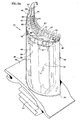
- Hohles Strömungsprofil (54), das eine Druckseitenwand (42) und eine Sogseitenwand (44) aufweist, wobei die Druckseitenwand und die Sogseitenwand an Vorder- und Hinterkanten (46, 48) verbunden sind und sich von einer Wurzel (50) zu einer Spitze (36) erstrecken, dadurch gekennzeichnet, dass das hohle Strömungsprofil (54) einen eingebetteten Mikrokreislauf in der Spitze (36) aufweist, wobei der eingebettete Mikrokreislauf umfasst:zumindest ein Plenum (78), das zwischen der Druckseitenwand und der Sogseitenwand (42, 44) angeordnet ist;eine Mehrzahl von Einlässen (70), durch welche Kühlungsluft eintreten kann, wobei die Mehrzahl von Einlässen (70) nahe der Sogseitenwand (44) und in Strömungsverbindung mit dem Plenum (78) sind;eine Mehrzahl von Verbindungsmikrodurchgängen (80), die in Strömungsverbindung mit den Einlässen (70) stehen, und durch welche die Kühlungsluft eintreten kann;eine Mehrzahl von Auslässen (72), die in Strömungsverbindung mit den Verbindungsmikrodurchgängen (80) stehen, wobei die Auslässe (72) innerhalb der Druckscitenwand (42) angeordnet sind und die Kühlungsluft von den Verbindungsmikrodurchgängen an einen Bereich außerhalb der Spitze des hohlen Strömungsprofils überleiten, wobei sich die Verbindungsmikrodurchgänge (80) über die Spitzc (36) von den Einlässen (70) zu den Auslässen (72) erstrecken, und wobei sich die Verbindungsmikrodurchgänge (80) zwischen den Einlässen (70) und den Auslässen (72) untereinander verbinden; undwobei die Mikrodurchgänge (80) derart ausgerichtet sind, dass sie die Spitze (36) zwischen der Sogseitenwand und der Druckseitenwand (42, 44) im Wesentlichen durchlaufen, wobei die Mikrodurchgänge (80) angeordnet sind, um mit Kühlungsluft von den Einlässen (70) gespeist zu werden, und um die Kühlungsluft durch die Auslässe (72) abzulassen.
- Hohles Strömungsprofil nach Anspruch 1, des Weiteren beinhaltend zumindest einen Vorsprung (88), der in dem Mikrokreislauf und in dem Weg der Kühlungsluft angeordnet ist, um die Kühlungsluft, die innerhalb des Mikrokreislaufs strömt, zu verwirbeln.
- Hohles Strömungsprofil nach Anspruch 2, wobei der Vorsprung (88) ausgebildet ist, um Verwirbelung innerhalb des Mikrokreislaufs zu fördern und dessen Wärmeleitfäche zu erhöhen,
- Hohles Strömungsprofil nach Anspruch 3, wobei der Vorsprung (88) Kleeblatt-förmig ist.
- Hohles Strömungsprofil nach einem der Ansprüche 1 bis 4, wobei die Einlässe (70) in Strömungsverbindung mit der Kühlungsluft innerhalb eines Kühlungskreislaufs (38) stehen, der innerhalb des Strömungsprofils (54) angeordnet ist, wobei die Einlässe (70) auf die Spitze (36) gerichtet sind zum Auftreffen der Kühlungsluft auf diese.
- Hohles Strömungsprofil nach einem der Ansprüche 1 bis 5, wobei die Auslässe (72) nach oben in Richtung der Spitze (36) in einem Bereich zwischen etwa 0 Grad bis etwa 45 Grad in Bezug auf eine Achse, die normal zu einer oberen Außenfläche (67) der Spitze ist, angewinkelt sind.
- Hohles Strömungsprofil nach einem der Ansprüche 1 bis 6, des Weiteren beinhaltend:zumindest einen Mikrodurchgang (86), der in etwa entlang einer Hauptkrümmungslinie (60) des Strömungsprofils (54) nahe der Hinterkante (48) ausgerichtet ist und in Strömungsverbindung mit zumindest einem der Mikrodurchgänge (80) steht;wobei die Kühlungsluft von den Verbindungsmikrodurchgängen (80) in den Mikrodurchgang (86) eintritt, der entlang der Hauptkrümmungslinie (60) des Strömungsprofils nahe der Hinterkante (68) ausgerichtet ist, und durch einen Auslass (72) austritt, der innerhalb einer äußeren Fläche der Druckseitenwand (42) nahe der Hinterkante (48) angeordnet ist.
- Hohles Strömungsprofil nach einem der Ansprüche 1 bis 6, wobei die Kühlungsluft durch die Mikrodurchgänge (80) in eine Richtung strömt, die der Richtung eines Gasstroms entgegensteht, wobei der Gasstrom über eine äußere Fläche des Strömungsprofils strömt.
- Hohles Strömungsprofil nach Anspruch 1, wobei eine obere Fläche (67) der Spitze (36) des Strömungsprofils (54) einen Absatz (92) benachbart der Druckseitenwand (42) beinhaltet, und wobei die Auslässe (72) innerhalb des Absatzes (92) derart angeordnet sind, dass Kühlungsluft von den Auslässen (72) auf die obere Fläche (67) ausgelassen wird.
- Verfahren zum Kühlen einer Spitze (36) einer zur Verwendung in einer Gasturbine geeigneten Turbinenschaufel (54), umfassend die Schritte:Herstellen eines eingebetteten Mikrokreislaufs unter einer Fläche der Spitze, wobei der Mikrokreislauf umfasst:einen Einlass (70), um das Passieren von Kühlungsströmung von einer Kühlungsfluidquelle innerhalb der Turbinenschaufel zu erlauben, wobei der Einlass (70) nahe einer Sogseitenwand (44) ist;eine Mehrzahl von verbindenden Mikrodurchgängen (80), die in Strömungsverbindung mit dem Einlass (70) stchen, und durch welche Kühlungsströmung eintreten kann; undeinen Auslass (72) in Strömungsverbindung mit den verbindenden Mikrodurchgängen (80), wobei der Auslass die Kühlungsströmung von den verbindenden Mikrodurchgängen (80) an einen Bereich außerhalb der Spitze (36) des Stromungsprofils überleitet, wobei sich die verbindenden Mikrodurchgänge (80) über die Spitze von dem Einlass (70) zu dem Auslass (72) erstrecken, und wobei sich die verbindenden Mikrodurchgänge (80) zwischen dem Einlass (70) und dem Auslass (72) untereinander verbinden, wobei die Mikrodurchgänge (80) derart ausgerichtet sind, dass sie die Spitze (36) zwischen der Sogseitenwand (44) und der Druckseitenwand (42) im Wesentlichen durchlaufen, wobei die Mikrodurchgänge (80) angeordnet sind, um mit Kühlungsströmung von dem Einlass (70) gespeist zu werden, und um die Kühlungsströmung durch den Auslass (72) abzulassen; undBereitstellen von Kühlungsströmung von der Kühlungsfluidquelle zum Strömen in den Einlass durch die Mehrzahl von verbindenden Mikrodurchgängen (80) und aus dem Auslass (42), um an der Spitze der Schaufel in den Gasstrom auszutreten.
- Verfahren nach Anspruch 10, wobei das Herstellen des Mikrokreislaufs die Schritte umfasst:Ausformen von feuerfestem Metall in die Gestalt der Mikrodurchgänge (80);Einfahren des feuerfesten Metalls in eine Form zum Gießen der Schaufel; undEntfernen des feuerfesten Metalls von der Schaufel nach dem Gießen.
- Verfahren nach Anspruch 11, wobei die Schaufel (54) aus einem Metall hergestellt ist, das aus der Gruppe bestehend aus Nickel-basierenden Legierungen und Kobaltbasierenden Legierungen ausgewählt ist.
- Verfahren nach Anspruch 12, wobei die Mikrodurchgänge (80) unter der Oberfläche der Schaufel in einem Abstand nicht größer als etwa 0,76 mm (0,03 Inches) hergestellt sind.
- Verfahren nach Anspruch 10, wobei der Mikrokreislauf des Weiteren zumindest einen Vorsprung (88) beinhaltet, wobei sich der zumindest eine Vorsprung radial zumindest zum Teil in den Weg der Kühlungsströmung in dem Mikrodurchgang (80) erstreckt.
- Verfahren nach Anspruch 10, wobei die Mikrodurchgänge (80) von dem Einlass (70) zu dem Auslass (72) konvergieren.
Applications Claiming Priority (2)
| Application Number | Priority Date | Filing Date | Title |
|---|---|---|---|
| US358646 | 2003-02-05 | ||
| US10/358,646 US6932571B2 (en) | 2003-02-05 | 2003-02-05 | Microcircuit cooling for a turbine blade tip |
Publications (3)
| Publication Number | Publication Date |
|---|---|
| EP1445424A2 EP1445424A2 (de) | 2004-08-11 |
| EP1445424A3 EP1445424A3 (de) | 2006-12-27 |
| EP1445424B1 true EP1445424B1 (de) | 2012-01-11 |
Family
ID=32655629
Family Applications (1)
| Application Number | Title | Priority Date | Filing Date |
|---|---|---|---|
| EP04250454A Expired - Fee Related EP1445424B1 (de) | 2003-02-05 | 2004-01-28 | Hohlschaufel mit eingebautem Kreislauf zur Schaufelspitzenkühlung |
Country Status (10)
| Country | Link |
|---|---|
| US (1) | US6932571B2 (de) |
| EP (1) | EP1445424B1 (de) |
| JP (1) | JP2004239263A (de) |
| KR (1) | KR20040071045A (de) |
| CN (4) | CN1550650A (de) |
| CA (1) | CA2456628A1 (de) |
| IL (1) | IL160163A (de) |
| PL (1) | PL364838A1 (de) |
| SG (1) | SG127708A1 (de) |
| TW (1) | TWI257447B (de) |
Families Citing this family (78)
| Publication number | Priority date | Publication date | Assignee | Title |
|---|---|---|---|---|
| US6971851B2 (en) * | 2003-03-12 | 2005-12-06 | Florida Turbine Technologies, Inc. | Multi-metered film cooled blade tip |
| EP1529580B1 (de) * | 2003-10-29 | 2009-01-07 | Siemens Aktiengesellschaft | Gussform |
| GB2412411A (en) * | 2004-03-25 | 2005-09-28 | Rolls Royce Plc | A cooling arrangement |
| US7334991B2 (en) * | 2005-01-07 | 2008-02-26 | Siemens Power Generation, Inc. | Turbine blade tip cooling system |
| US7217088B2 (en) * | 2005-02-02 | 2007-05-15 | Siemens Power Generation, Inc. | Cooling fluid preheating system for an airfoil in a turbine engine |
| US7600966B2 (en) * | 2006-01-17 | 2009-10-13 | United Technologies Corporation | Turbine airfoil with improved cooling |
| US7695246B2 (en) * | 2006-01-31 | 2010-04-13 | United Technologies Corporation | Microcircuits for small engines |
| US20100247328A1 (en) * | 2006-06-06 | 2010-09-30 | United Technologies Corporation | Microcircuit cooling for blades |
| US20080008599A1 (en) * | 2006-07-10 | 2008-01-10 | United Technologies Corporation | Integral main body-tip microcircuits for blades |
| US7553131B2 (en) * | 2006-07-21 | 2009-06-30 | United Technologies Corporation | Integrated platform, tip, and main body microcircuits for turbine blades |
| US7699583B2 (en) * | 2006-07-21 | 2010-04-20 | United Technologies Corporation | Serpentine microcircuit vortex turbulatons for blade cooling |
| EP1882818B1 (de) * | 2006-07-18 | 2013-06-05 | United Technologies Corporation | Wirbelerzeuger in serpentinenartigen Mikrokanälen zur Schaufelkühlung |
| US7513744B2 (en) * | 2006-07-18 | 2009-04-07 | United Technologies Corporation | Microcircuit cooling and tip blowing |
| US7581927B2 (en) * | 2006-07-28 | 2009-09-01 | United Technologies Corporation | Serpentine microcircuit cooling with pressure side features |
| US7537431B1 (en) | 2006-08-21 | 2009-05-26 | Florida Turbine Technologies, Inc. | Turbine blade tip with mini-serpentine cooling circuit |
| US20080131285A1 (en) * | 2006-11-30 | 2008-06-05 | United Technologies Corporation | RMC-defined tip blowing slots for turbine blades |
| US7641444B1 (en) * | 2007-01-17 | 2010-01-05 | Florida Turbine Technologies, Inc. | Serpentine flow circuit with tip section cooling channels |
| US7713026B1 (en) | 2007-03-06 | 2010-05-11 | Florida Turbine Technologies, Inc. | Turbine bladed with tip cooling |
| EP2128450B1 (de) * | 2007-03-27 | 2018-05-16 | IHI Corporation | Gebläserotorflügelstützstruktur und diese verwendendes mantelstromtriebwerk |
| US20080276622A1 (en) * | 2007-05-07 | 2008-11-13 | Thomas Edward Johnson | Fuel nozzle and method of fabricating the same |
| US7845908B1 (en) | 2007-11-19 | 2010-12-07 | Florida Turbine Technologies, Inc. | Turbine blade with serpentine flow tip rail cooling |
| US8079811B1 (en) * | 2008-01-23 | 2011-12-20 | Florida Turbine Technologies, Inc. | Turbine blade with multi-impingement cooled squealer tip |
| US8157527B2 (en) * | 2008-07-03 | 2012-04-17 | United Technologies Corporation | Airfoil with tapered radial cooling passage |
| US8348614B2 (en) * | 2008-07-14 | 2013-01-08 | United Technologies Corporation | Coolable airfoil trailing edge passage |
| US8317461B2 (en) * | 2008-08-27 | 2012-11-27 | United Technologies Corporation | Gas turbine engine component having dual flow passage cooling chamber formed by single core |
| US8572844B2 (en) * | 2008-08-29 | 2013-11-05 | United Technologies Corporation | Airfoil with leading edge cooling passage |
| US8043059B1 (en) * | 2008-09-12 | 2011-10-25 | Florida Turbine Technologies, Inc. | Turbine blade with multi-vortex tip cooling and sealing |
| US8303252B2 (en) * | 2008-10-16 | 2012-11-06 | United Technologies Corporation | Airfoil with cooling passage providing variable heat transfer rate |
| US8109725B2 (en) | 2008-12-15 | 2012-02-07 | United Technologies Corporation | Airfoil with wrapped leading edge cooling passage |
| CN101832154B (zh) * | 2009-03-11 | 2013-03-27 | 中国科学院工程热物理研究所 | 一种航空发动机涡轮叶片气膜冷却方法 |
| US8011888B1 (en) * | 2009-04-18 | 2011-09-06 | Florida Turbine Technologies, Inc. | Turbine blade with serpentine cooling |
| US8066485B1 (en) * | 2009-05-15 | 2011-11-29 | Florida Turbine Technologies, Inc. | Turbine blade with tip section cooling |
| US8262357B2 (en) * | 2009-05-15 | 2012-09-11 | Siemens Energy, Inc. | Extended length holes for tip film and tip floor cooling |
| US20110110772A1 (en) * | 2009-11-11 | 2011-05-12 | Arrell Douglas J | Turbine Engine Components with Near Surface Cooling Channels and Methods of Making the Same |
| US8511994B2 (en) * | 2009-11-23 | 2013-08-20 | United Technologies Corporation | Serpentine cored airfoil with body microcircuits |
| US8616845B1 (en) * | 2010-06-23 | 2013-12-31 | Florida Turbine Technologies, Inc. | Turbine blade with tip cooling circuit |
| US9085988B2 (en) * | 2010-12-24 | 2015-07-21 | Rolls-Royce North American Technologies, Inc. | Gas turbine engine flow path member |
| US20120183398A1 (en) * | 2011-01-13 | 2012-07-19 | General Electric Company | System and method for controlling flow through a rotor |
| US8876484B2 (en) | 2011-08-05 | 2014-11-04 | Hamilton Sundstrand Corporation | Turbine blade pocket pin stress relief |
| US20130236329A1 (en) * | 2012-03-09 | 2013-09-12 | United Technologies Corporation | Rotor blade with one or more side wall cooling circuits |
| US9429027B2 (en) | 2012-04-05 | 2016-08-30 | United Technologies Corporation | Turbine airfoil tip shelf and squealer pocket cooling |
| US9279331B2 (en) | 2012-04-23 | 2016-03-08 | United Technologies Corporation | Gas turbine engine airfoil with dirt purge feature and core for making same |
| US9422817B2 (en) | 2012-05-31 | 2016-08-23 | United Technologies Corporation | Turbine blade root with microcircuit cooling passages |
| US10100646B2 (en) * | 2012-08-03 | 2018-10-16 | United Technologies Corporation | Gas turbine engine component cooling circuit |
| US9103217B2 (en) * | 2012-10-31 | 2015-08-11 | General Electric Company | Turbine blade tip with tip shelf diffuser holes |
| US10502065B2 (en) | 2013-06-17 | 2019-12-10 | United Technologies Corporation | Gas turbine engine component with rib support |
| WO2015053846A2 (en) * | 2013-08-05 | 2015-04-16 | United Technologies Corporation | Engine component having platform with passageway |
| US9856739B2 (en) * | 2013-09-18 | 2018-01-02 | Honeywell International Inc. | Turbine blades with tip portions having converging cooling holes |
| US9816389B2 (en) | 2013-10-16 | 2017-11-14 | Honeywell International Inc. | Turbine rotor blades with tip portion parapet wall cavities |
| US9879544B2 (en) | 2013-10-16 | 2018-01-30 | Honeywell International Inc. | Turbine rotor blades with improved tip portion cooling holes |
| WO2015060973A1 (en) * | 2013-10-23 | 2015-04-30 | United Technologies Corporation | Turbine airfoil cooling core exit |
| EP3060363B1 (de) * | 2013-10-24 | 2021-10-27 | Raytheon Technologies Corporation | Verlorene kernformung zur herstellung von kühlkanälen |
| US10626730B2 (en) | 2013-12-17 | 2020-04-21 | United Technologies Corporation | Enhanced cooling for blade tip |
| EP3086893B1 (de) | 2013-12-23 | 2019-07-24 | United Technologies Corporation | Strukturrahmen eines verlorenem kerns |
| US9488057B2 (en) | 2014-06-10 | 2016-11-08 | Aeronautical Systems Research Division National Chung Shan Institute Of Science And Technology | Micro jet gas film generation apparatus |
| US10408064B2 (en) * | 2014-07-09 | 2019-09-10 | Siemens Aktiengesellschaft | Impingement jet strike channel system within internal cooling systems |
| US10280761B2 (en) * | 2014-10-29 | 2019-05-07 | United Technologies Corporation | Three dimensional airfoil micro-core cooling chamber |
| US9995147B2 (en) | 2015-02-11 | 2018-06-12 | United Technologies Corporation | Blade tip cooling arrangement |
| DE112016004421B4 (de) * | 2015-09-29 | 2021-10-21 | Mitsubishi Power, Ltd. | Laufschaufel und damit ausgestattete gasturbine |
| TWI616537B (zh) * | 2015-11-19 | 2018-03-01 | 財團法人金屬工業研究發展中心 | 金屬材熱處理方法 |
| US10428659B2 (en) * | 2015-12-21 | 2019-10-01 | United Technologies Corporation | Crossover hole configuration for a flowpath component in a gas turbine engine |
| US10196903B2 (en) * | 2016-01-15 | 2019-02-05 | General Electric Company | Rotor blade cooling circuit |
| US10731472B2 (en) | 2016-05-10 | 2020-08-04 | General Electric Company | Airfoil with cooling circuit |
| US10704395B2 (en) | 2016-05-10 | 2020-07-07 | General Electric Company | Airfoil with cooling circuit |
| US10358928B2 (en) * | 2016-05-10 | 2019-07-23 | General Electric Company | Airfoil with cooling circuit |
| US10544683B2 (en) | 2016-08-30 | 2020-01-28 | Rolls-Royce Corporation | Air-film cooled component for a gas turbine engine |
| US10519780B2 (en) | 2016-09-13 | 2019-12-31 | Rolls-Royce Corporation | Dual-walled components for a gas turbine engine |
| US10801325B2 (en) * | 2017-03-27 | 2020-10-13 | Raytheon Technologies Corporation | Turbine blade with tip vortex control and tip shelf |
| US10502069B2 (en) * | 2017-06-07 | 2019-12-10 | General Electric Company | Turbomachine rotor blade |
| US10358926B2 (en) * | 2017-08-11 | 2019-07-23 | General Electric Company | Low-noise airfoil for an open rotor |
| US10570750B2 (en) | 2017-12-06 | 2020-02-25 | General Electric Company | Turbine component with tip rail cooling passage |
| US10408065B2 (en) | 2017-12-06 | 2019-09-10 | General Electric Company | Turbine component with rail coolant directing chamber |
| US11208899B2 (en) | 2018-03-14 | 2021-12-28 | General Electric Company | Cooling assembly for a turbine assembly |
| US11156102B2 (en) | 2018-03-19 | 2021-10-26 | General Electric Company | Blade having a tip cooling cavity and method of making same |
| KR102021139B1 (ko) | 2018-04-04 | 2019-10-18 | 두산중공업 주식회사 | 스퀼러 팁을 구비한 터빈 블레이드 |
| US10787932B2 (en) | 2018-07-13 | 2020-09-29 | Honeywell International Inc. | Turbine blade with dust tolerant cooling system |
| EP4028643B1 (de) * | 2019-10-28 | 2023-12-06 | Siemens Energy Global GmbH & Co. KG | Turbinenschaufel, verfahren zur herstellung einer turbinenschaufel und verfahren zur überholung einer turbinenschaufel |
| CN112648018A (zh) * | 2020-12-01 | 2021-04-13 | 日照黎阳工业装备有限公司 | 可保证叶片前缘高效冷却的发动机用高温合金叶片 |
Family Cites Families (12)
| Publication number | Priority date | Publication date | Assignee | Title |
|---|---|---|---|---|
| GB2077363A (en) * | 1980-06-05 | 1981-12-16 | United Technologies Corp | Wafer tip cap for rotor blades |
| US4768700A (en) * | 1987-08-17 | 1988-09-06 | General Motors Corporation | Diffusion bonding method |
| US5261789A (en) * | 1992-08-25 | 1993-11-16 | General Electric Company | Tip cooled blade |
| US5476364A (en) * | 1992-10-27 | 1995-12-19 | United Technologies Corporation | Tip seal and anti-contamination for turbine blades |
| US5403159A (en) * | 1992-11-30 | 1995-04-04 | United Technoligies Corporation | Coolable airfoil structure |
| GB2298245B (en) * | 1995-02-23 | 1998-10-28 | Bmw Rolls Royce Gmbh | A turbine-blade arrangement comprising a cooled shroud band |
| US6247896B1 (en) * | 1999-06-23 | 2001-06-19 | United Technologies Corporation | Method and apparatus for cooling an airfoil |
| US6164914A (en) * | 1999-08-23 | 2000-12-26 | General Electric Company | Cool tip blade |
| US6402470B1 (en) * | 1999-10-05 | 2002-06-11 | United Technologies Corporation | Method and apparatus for cooling a wall within a gas turbine engine |
| US6280140B1 (en) * | 1999-11-18 | 2001-08-28 | United Technologies Corporation | Method and apparatus for cooling an airfoil |
| US6609894B2 (en) * | 2001-06-26 | 2003-08-26 | General Electric Company | Airfoils with improved oxidation resistance and manufacture and repair thereof |
| US6705831B2 (en) * | 2002-06-19 | 2004-03-16 | United Technologies Corporation | Linked, manufacturable, non-plugging microcircuits |
-
2003
- 2003-02-05 US US10/358,646 patent/US6932571B2/en not_active Expired - Lifetime
- 2003-10-27 KR KR1020030074962A patent/KR20040071045A/ko not_active Application Discontinuation
-
2004
- 2004-01-28 SG SG200400363A patent/SG127708A1/en unknown
- 2004-01-28 EP EP04250454A patent/EP1445424B1/de not_active Expired - Fee Related
- 2004-02-02 IL IL160163A patent/IL160163A/en not_active IP Right Cessation
- 2004-02-02 CA CA002456628A patent/CA2456628A1/en not_active Abandoned
- 2004-02-04 TW TW093102515A patent/TWI257447B/zh not_active IP Right Cessation
- 2004-02-05 CN CNA2004100451286A patent/CN1550650A/zh active Pending
- 2004-02-05 PL PL04364838A patent/PL364838A1/xx not_active Application Discontinuation
- 2004-02-05 CN CNA2007100062510A patent/CN101004141A/zh active Pending
- 2004-02-05 CN CNA2007100062506A patent/CN101004147A/zh active Pending
- 2004-02-05 CN CNA2007100062493A patent/CN101004140A/zh active Pending
- 2004-02-05 JP JP2004028870A patent/JP2004239263A/ja active Pending
Also Published As
| Publication number | Publication date |
|---|---|
| CN101004141A (zh) | 2007-07-25 |
| TWI257447B (en) | 2006-07-01 |
| TW200504275A (en) | 2005-02-01 |
| IL160163A (en) | 2007-06-03 |
| JP2004239263A (ja) | 2004-08-26 |
| CN101004147A (zh) | 2007-07-25 |
| EP1445424A3 (de) | 2006-12-27 |
| KR20040071045A (ko) | 2004-08-11 |
| CN101004140A (zh) | 2007-07-25 |
| IL160163A0 (en) | 2004-07-25 |
| CA2456628A1 (en) | 2004-08-05 |
| CN1550650A (zh) | 2004-12-01 |
| PL364838A1 (en) | 2004-08-09 |
| US6932571B2 (en) | 2005-08-23 |
| SG127708A1 (en) | 2006-12-29 |
| EP1445424A2 (de) | 2004-08-11 |
| US20040151587A1 (en) | 2004-08-05 |
Similar Documents
| Publication | Publication Date | Title |
|---|---|---|
| EP1445424B1 (de) | Hohlschaufel mit eingebautem Kreislauf zur Schaufelspitzenkühlung | |
| US6955522B2 (en) | Method and apparatus for cooling an airfoil | |
| US6607355B2 (en) | Turbine airfoil with enhanced heat transfer | |
| EP1001137B1 (de) | Gasturbinenschaufel mit serpentinenförmigen Kühlkanälen | |
| CA2668605C (en) | Crossflow turbine airfoil | |
| JP4546760B2 (ja) | 一体化されたブリッジを備えたタービンブレード | |
| US5690473A (en) | Turbine blade having transpiration strip cooling and method of manufacture | |
| EP1221538B1 (de) | Gekühlte Turbinenleitschaufel | |
| US7097425B2 (en) | Microcircuit cooling for a turbine airfoil | |
| JP4576177B2 (ja) | 収束ピン冷却式翼形部 | |
| US7011502B2 (en) | Thermal shield turbine airfoil | |
| EP1008724B1 (de) | Schaufel eines Gasturbinentriebwerks | |
| EP1544411B1 (de) | Verfahren zur Frequenzverstimmung einer Turbinenschaufel | |
| EP1001136B1 (de) | Strömungsmaschinenschaufel mit aparter Kühlung der Anströmkante | |
| EP1001135A2 (de) | Turbinenschaufel mit serieller Prallkühlung | |
| EP1088964A2 (de) | Schlitz zur Prallkühlung der Anströmkante einer Turbinenschaufel |
Legal Events
| Date | Code | Title | Description |
|---|---|---|---|
| PUAI | Public reference made under article 153(3) epc to a published international application that has entered the european phase |
Free format text: ORIGINAL CODE: 0009012 |
|
| AK | Designated contracting states |
Kind code of ref document: A2 Designated state(s): AT BE BG CH CY CZ DE DK EE ES FI FR GB GR HU IE IT LI LU MC NL PT RO SE SI SK TR |
|
| AX | Request for extension of the european patent |
Extension state: AL LT LV MK |
|
| PUAL | Search report despatched |
Free format text: ORIGINAL CODE: 0009013 |
|
| AK | Designated contracting states |
Kind code of ref document: A3 Designated state(s): AT BE BG CH CY CZ DE DK EE ES FI FR GB GR HU IE IT LI LU MC NL PT RO SE SI SK TR |
|
| AX | Request for extension of the european patent |
Extension state: AL LT LV MK |
|
| 17P | Request for examination filed |
Effective date: 20070205 |
|
| 17Q | First examination report despatched |
Effective date: 20070620 |
|
| AKX | Designation fees paid |
Designated state(s): DE FR GB IT |
|
| GRAP | Despatch of communication of intention to grant a patent |
Free format text: ORIGINAL CODE: EPIDOSNIGR1 |
|
| RTI1 | Title (correction) |
Free format text: HOLLOW AIRFOIL PROVIDED WITH AN EMBEDDED MICROCIRCUIT FOR TIP COOLING |
|
| GRAS | Grant fee paid |
Free format text: ORIGINAL CODE: EPIDOSNIGR3 |
|
| GRAA | (expected) grant |
Free format text: ORIGINAL CODE: 0009210 |
|
| AK | Designated contracting states |
Kind code of ref document: B1 Designated state(s): DE FR GB IT |
|
| REG | Reference to a national code |
Ref country code: GB Ref legal event code: FG4D |
|
| REG | Reference to a national code |
Ref country code: DE Ref legal event code: R081 Ref document number: 602004036063 Country of ref document: DE Owner name: UNITED TECHNOLOGIES CORP. (N.D.GES.D. STAATES , US Free format text: FORMER OWNER: UNITED TECHNOLOGIES CORP. (N.D.GES.D. STAATES DELAWARE), HARTFORD, CONN., US |
|
| REG | Reference to a national code |
Ref country code: DE Ref legal event code: R096 Ref document number: 602004036063 Country of ref document: DE Effective date: 20120315 |
|
| PLBE | No opposition filed within time limit |
Free format text: ORIGINAL CODE: 0009261 |
|
| STAA | Information on the status of an ep patent application or granted ep patent |
Free format text: STATUS: NO OPPOSITION FILED WITHIN TIME LIMIT |
|
| PG25 | Lapsed in a contracting state [announced via postgrant information from national office to epo] |
Ref country code: IT Free format text: LAPSE BECAUSE OF FAILURE TO SUBMIT A TRANSLATION OF THE DESCRIPTION OR TO PAY THE FEE WITHIN THE PRESCRIBED TIME-LIMIT Effective date: 20120111 |
|
| 26N | No opposition filed |
Effective date: 20121012 |
|
| REG | Reference to a national code |
Ref country code: DE Ref legal event code: R097 Ref document number: 602004036063 Country of ref document: DE Effective date: 20121012 |
|
| REG | Reference to a national code |
Ref country code: FR Ref legal event code: ST Effective date: 20130104 |
|
| PG25 | Lapsed in a contracting state [announced via postgrant information from national office to epo] |
Ref country code: FR Free format text: LAPSE BECAUSE OF NON-PAYMENT OF DUE FEES Effective date: 20120312 |
|
| REG | Reference to a national code |
Ref country code: DE Ref legal event code: R082 Ref document number: 602004036063 Country of ref document: DE Representative=s name: SCHMITT-NILSON SCHRAUD WAIBEL WOHLFROM PATENTA, DE |
|
| REG | Reference to a national code |
Ref country code: DE Ref legal event code: R082 Ref document number: 602004036063 Country of ref document: DE Representative=s name: SCHMITT-NILSON SCHRAUD WAIBEL WOHLFROM PATENTA, DE Ref country code: DE Ref legal event code: R081 Ref document number: 602004036063 Country of ref document: DE Owner name: UNITED TECHNOLOGIES CORP. (N.D.GES.D. STAATES , US Free format text: FORMER OWNER: UNITED TECHNOLOGIES CORPORATION, HARTFORD, CONN., US |
|
| PGFP | Annual fee paid to national office [announced via postgrant information from national office to epo] |
Ref country code: DE Payment date: 20191218 Year of fee payment: 17 |
|
| PGFP | Annual fee paid to national office [announced via postgrant information from national office to epo] |
Ref country code: GB Payment date: 20201218 Year of fee payment: 18 |
|
| REG | Reference to a national code |
Ref country code: DE Ref legal event code: R119 Ref document number: 602004036063 Country of ref document: DE |
|
| PG25 | Lapsed in a contracting state [announced via postgrant information from national office to epo] |
Ref country code: DE Free format text: LAPSE BECAUSE OF NON-PAYMENT OF DUE FEES Effective date: 20210803 |
|
| GBPC | Gb: european patent ceased through non-payment of renewal fee |
Effective date: 20220128 |
|
| PG25 | Lapsed in a contracting state [announced via postgrant information from national office to epo] |
Ref country code: GB Free format text: LAPSE BECAUSE OF NON-PAYMENT OF DUE FEES Effective date: 20220128 |