EP1001135A2 - Aube de turbomachine refroidie par impact en cascade - Google Patents
Aube de turbomachine refroidie par impact en cascade Download PDFInfo
- Publication number
- EP1001135A2 EP1001135A2 EP99309107A EP99309107A EP1001135A2 EP 1001135 A2 EP1001135 A2 EP 1001135A2 EP 99309107 A EP99309107 A EP 99309107A EP 99309107 A EP99309107 A EP 99309107A EP 1001135 A2 EP1001135 A2 EP 1001135A2
- Authority
- EP
- European Patent Office
- Prior art keywords
- airfoil
- cooling air
- sidewall
- cooling
- chamber
- Prior art date
- Legal status (The legal status is an assumption and is not a legal conclusion. Google has not performed a legal analysis and makes no representation as to the accuracy of the status listed.)
- Withdrawn
Links
Images

Classifications
-
- F—MECHANICAL ENGINEERING; LIGHTING; HEATING; WEAPONS; BLASTING
- F01—MACHINES OR ENGINES IN GENERAL; ENGINE PLANTS IN GENERAL; STEAM ENGINES
- F01D—NON-POSITIVE DISPLACEMENT MACHINES OR ENGINES, e.g. STEAM TURBINES
- F01D5/00—Blades; Blade-carrying members; Heating, heat-insulating, cooling or antivibration means on the blades or the members
- F01D5/12—Blades
- F01D5/14—Form or construction
- F01D5/18—Hollow blades, i.e. blades with cooling or heating channels or cavities; Heating, heat-insulating or cooling means on blades
- F01D5/187—Convection cooling
-
- F—MECHANICAL ENGINEERING; LIGHTING; HEATING; WEAPONS; BLASTING
- F05—INDEXING SCHEMES RELATING TO ENGINES OR PUMPS IN VARIOUS SUBCLASSES OF CLASSES F01-F04
- F05D—INDEXING SCHEME FOR ASPECTS RELATING TO NON-POSITIVE-DISPLACEMENT MACHINES OR ENGINES, GAS-TURBINES OR JET-PROPULSION PLANTS
- F05D2260/00—Function
- F05D2260/20—Heat transfer, e.g. cooling
- F05D2260/201—Heat transfer, e.g. cooling by impingement of a fluid
-
- F—MECHANICAL ENGINEERING; LIGHTING; HEATING; WEAPONS; BLASTING
- F05—INDEXING SCHEMES RELATING TO ENGINES OR PUMPS IN VARIOUS SUBCLASSES OF CLASSES F01-F04
- F05D—INDEXING SCHEME FOR ASPECTS RELATING TO NON-POSITIVE-DISPLACEMENT MACHINES OR ENGINES, GAS-TURBINES OR JET-PROPULSION PLANTS
- F05D2260/00—Function
- F05D2260/20—Heat transfer, e.g. cooling
- F05D2260/202—Heat transfer, e.g. cooling by film cooling
Definitions
- the present invention relates generally to gas turbine engines, and, more specifically, to cooled turbine blades and stator vanes therein.
- air is pressurized in a compressor and channeled to a combustor wherein it is mixed with fuel and ignited for generating hot combustion gases.
- the combustion gases flow downstream through one or more turbines which extract energy therefrom for powering the compressor and producing output power.
- Turbine rotor blades and stationary nozzle vanes disposed downstream from the combustor have hollow airfoils supplied with a portion of compressed air bled from the compressor for cooling these components to effect useful lives thereof. Any air bled from the compressor necessarily is not used for producing power and correspondingly decreases the overall efficiency of the engine.
- Typical cooling configurations include serpentine cooling passages for convection cooling the inside of blade and vane airfoils, which may be enhanced using various forms of turbulators. Internal impingement holes are also used for impingement cooling inner surfaces of the airfoils. And, film cooling holes extend through the airfoil sidewalls for providing film cooling of the external surfaces thereof.
- Airfoil cooling design is rendered additionally more complex since the airfoils have a generally concave pressure side and an opposite, generally convex suction side extending axially between leading and trailing edges.
- the combustion gases flow over the pressure and suction sides with varying pressure and velocity distributions thereover. Accordingly, the heat load into the airfoil varies between its leading and trailing edges, and also varies from the radially inner root thereof to the radially outer tip thereof.
- a typical film cooling hole is inclined through the airfoil walls in the aft direction at a shallow angle to produce a thin boundary layer of cooling air downstream therefrom.
- the pressure of the film cooling air must necessarily be greater than the external pressure of the combustion gases to prevent backflow or ingestion of the hot combustion gases into the airfoil.
- a gas turbine engine airfoil which includes first and second sidewalls joined together at opposite leading and trailing edges, and extending longitudinally from a root to a tip.
- the sidewalls are spaced apart from each other to define in part first and second adjoining flow chambers extending longitudinally therein, and defined in additional part by corresponding first and second partitions disposed between the sidewalls.
- the second partition is common to both chambers, and both partitions include respective pluralities of first and second inlet holes sized to meter cooling air therethrough in series between the chambers.
- Figure 1 is an isometric view of an exemplary gas turbine engine turbine rotor blade having an airfoil in accordance with an exemplary embodiment of the present invention.
- Figure 2 is a radial sectional view through the airfoil illustrated in Figure 1 and taken along line 2-2.
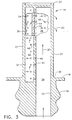
- Figure 3 is an elevational sectional view through the airfoil illustrated in Figure 2 and taken along line 3-3.
- FIG. 1 Illustrated in Figure 1 is a rotor blade 10 configured for attachment to the perimeter of a turbine rotor (not shown) in a gas turbine engine.
- the blade 10 is disposed downstream of a combustor and receives hot combustion gases 12 therefrom for extracting energy to rotate the turbine rotor for producing work.
- the blade 10 includes an airfoil 14 over which the combustion gases flow, and an integral platform 16 which defines the radially inner boundary of the combustion gas flowpath.
- a dovetail 18 extends integrally from the bottom of the platform and is configured for axial-entry into a corresponding dovetail slot in the perimeter of the rotor disk for retention therein.
- pressurized cooling air 20 is bled from a compressor (now shown) and routed radially upwardly through the dovetail 18 and into the hollow airfoil 14.
- the airfoil 14 is specifically configured in accordance with the present invention for improving effectiveness of the cooling air therein. Although the invention is described with respect to the airfoil for an exemplary rotor blade, it may also be applied to turbine stator vanes.
- the airfoil 14 includes a first or suction sidewall 22 and a circumferentially or laterally opposite second or pressure sidewall 24.
- the suction sidewall 22 is generally convex and the pressure sidewall is generally concave, and the sidewalls are joined together at axially opposite leading and trailing edges 26,28 which extend radially or longitudinally from a root 30 at the blade platform to a radially outer tip 32.
- FIG. 2 An exemplary radial section of the airfoil is illustrated in more detail in Figure 2 and has a profile conventionally configured for extracting energy from the combustion gases 12.
- the combustion gases 12 first impinge the airfoil 14 in the axial, downstream direction at the leading edge 26, with the combustion gases then splitting circumferentially for flow over both the suction sidewall 22 and the pressure sidewall 24 until they leave the airfoil at its trailing edge 28.
- the combustion gases 12 develop a maximum static pressure P 1 , with the pressure then varying correspondingly along the suction and pressure sidewalls. Due to the convex shape of the suction sidewall 22, the combustion gases are accelerated therearound to increase velocity thereof with a corresponding reduction in pressure, with an exemplary pressure P 2 located downstream of the leading edge on the suction sidewall being substantially lower than the maximum pressure at the leading edge.
- the concave shape of the pressure sidewall also controls the velocity of the combustion gases as they flow downstream or aft thereover with an exemplary pressure P 3 being less than the maximum pressure at the leading edge and greater than the corresponding pressure P 2 on the opposite convex side.
- the pressure profile along the suction sidewall 22 is substantially less in magnitude than the pressure profile along the pressure sidewall 24 to provide an aerodynamic lifting force on the airfoil for rotating the supporting turbine rotor to produce work.
- the cooling air 20 is provided to the airfoil typically at a single source pressure which is sufficiently high for driving the cooling air through various cooling circuits inside the airfoil and then being discharged through the airfoil into the turbine flowpath in which the combustion gases flow. Since the pressure and velocity profiles of the combustion gas flowing over the airfoil suction and pressure sidewalls varies, the differential pressure between the cooling air supplied inside the airfoil and the combustion gases flowing outside the airfoil correspondingly varies.
- blowing ratio of the cooling air discharged through holes in the airfoil may correspondingly vary and affect the cooling effectiveness of the discharged cooling air. This is most critical at the airfoil leading edge which experiences the maximum static pressure in the combustion gases with a steep gradient reduction in pressure along the suction sidewall near the leading edge, which like the leading edge itself requires effective cooling for acceptable blade life.
- the two sidewalls 22,24 are spaced apart circumferentially or laterally from each other to define in part first, second, and third flow chambers 34,36,38 extending radially or longitudinally therein, and defined in additional part by corresponding first, second, and third internal radial partitions 40,42,44 disposed between the sidewalls.
- the second partition 42 is common to both the first and second chambers 34,36, and similarly, the third partition 44 is common to both the second and third chambers 36,38.
- Each of the partitions includes a respective plurality of first, second, and third inlet holes 46,48,50 arranged in one or more longitudinal rows.
- the inlet holes are sized in accordance with the present invention to meter the cooling air 20 therethrough in series between the respective flow chambers 34,36,38 in turn for maximizing the cooling effectiveness thereof.
- Each of the partitions 40,42,44 preferably faces respective inner surfaces of at least one of the airfoil sidewalls with the corresponding inlet holes being directed thereat for impingement cooling the sidewalls with the successively used cooling air channeled therethrough.
- the airfoil has enhanced cooling due to channeling the same cooling air obliquely between the sidewalls thereof in series impingement therein.
- the three chambers 34-38 are dosed top and bottom and initially receive the cooling air from an inlet channel 52 extending longitudinally along the first partition 40 for initially supplying the cooling air to the first chamber 34 through the first inlet holes 46 arranged in two exemplary radial rows.
- the inlet channel 52 receives the cooling air from the blade dovetail with maximum pressure, minimum temperature, and suitable flowrate for flow through the airfoil.
- the three sets of inlet holes 46-50 extend obliquely through the respective partitions 40-44 generally perpendicularly therethrough in the radial section or plane illustrated in Figure 2 to discharge corresponding jets of the cooling air 20 in impingement against opposite walls of the respective chambers.
- the same cooling air is successively used for effecting series impingement in three discrete steps, with the temperature of the cooling air in each step increasing as it picks up heat from the airfoil, and the pressure thereof decreasing in each step after being metered through the corresponding inlet holes.
- the same cooling air is therefore used multiple times before being discharged from the airfoil, which therefore increases cooling efficiency and allows either a reduction in the required cooling air flowrate, or permits a higher temperature of the combustion gases 12.
- the cooling capability of the cooling air is thus more fully utilized since it is not simply discharged from the airfoil after a single impingement cooling operation.
- the first partition 40 is preferably disposed generally parallel between the opposite sidewalls 22,24 generally along a chordal line in the mid-chord region of the airfoil behind the leading edge.
- the first inlet holes 46 are disposed generally perpendicular therein for impinging the cooling air against the inner surface of the second, or pressure sidewall 24.
- the portion of the pressure sidewall adjoining the first chamber 34 is preferably imperforate and is primarily cooled by internal impingement cooling thereof.
- the second partition 42 is preferably disposed obliquely to both the pressure sidewall 24 and the first partition 40, with the second chamber 36 being disposed directly behind the leading edge 26 for defining a leading edge flow chamber.
- the first chamber 34 is thusly disposed directly aft of the leading edge chamber 36 along the pressure sidewall 24 in the airfoil midchord region.
- the third partition 44 preferably extends between the first sidewall 22 downstream from the leading edge 26 and intersects both the first and second partitions 40,42.
- the third inlet holes 50 extend obliquely through the third partition 44 to discharge jets of the cooling air in impingement against the inner surface of the first sidewall 22.
- the second sidewall 24 is imperforate at the first chamber 34, and the leading edge 26 includes a plurality of film cooling holes 54 extending therethrough in a plurality of axially spaced apart rows, and disposed in flow communication with the second chamber 36 for discharging cooling air therefrom for film cooling the airfoil leading edge.
- the leading edge film cooling holes 54 may have any conventional configuration such as conical diffusion holes for increasing film coverage and effectiveness while reducing the required amount of coolant flow.
- the first sidewall 22 preferably includes a plurality of film cooling gill holes 56 extending therethrough in flow communication with the third chamber 38 for discharging the cooling air therefrom for film cooling the first sidewall 22 downstream therefrom.
- the gill holes 56 may have any conventional configuration such as fan diffusion film holes for maximizing film cooling effectiveness thereof.
- the three chambers 34,36,38 are arranged for effecting series impingement cooling in three discrete steps, and film cooling in only two steps following the ultimate and penultimate ones of the impingement steps.
- the airfoil sidewalls are impingement cooled at each of the three chambers 34,36,38, and film cooling is effected from the leading edge 26 downstream therefrom along both the first sidewall 22 and the second sidewall 24 in the leading edge region subject to high heat loads which require effective cooling.
- the gill holes 56 which finally discharge the series impingement air re-energizes the film cooling layer from the leading edge on the first sidewall 22, which film extends downstream therefrom for a suitable distance toward the trailing edge 28.
- leading edge film cooling holes 54 protect the airfoil leading edge and re-energize the film cooling boundary from row to row, and in particular along the second sidewall 24.
- the film cooling air discharged from the last row of leading edge holes flows along the second sidewall 24 along the first chamber 34 for providing film cooling in this region in addition to the internal impingement cooling thereof.
- the third chamber 38 is defined in additional part by a fourth partition 58 which provides a common wall with the inlet channel 52.
- the fourth partition 58 is preferably imperforate and effectively isolates the third chamber 38 from the high pressure cooling air 20 initially introduced through the inlet channel 52.
- the cooling air 20 is provided to the third chamber 38 only after firstly passing from the inlet channel 52 to the first and second chambers 34,36 in turn. As the cooling air is metered in turn through the first, second, and third inlet holes 46,48,50 it experiences a significant pressure drop in steps.
- the cooling air channeled in the third chamber 38 is therefore at a substantially lower pressure than the cooling air initially provided in the inlet channel 52.
- the series impingement of the same cooling air 20 therefore more effectively utilizes that air prior to being discharged from the airfoil which increases the cooling efficiency thereof. This is particularly important for cooling the leading edge region of the airfoil subject to high heat load input from the combustion gases 12 which first engage the airfoil.
- the airfoil may also include additional flow channels disposed between the midchord region and the trailing edge 28 which may be configured in any conventional manner for cooling these regions of the airfoil as desired.
- additional flow channels disposed between the midchord region and the trailing edge 28 which may be configured in any conventional manner for cooling these regions of the airfoil as desired.
- the series impingement cooling configuration disclosed above is preferably located between the leading edge and midchord region of the airfoil, it may be otherwise configured to advantage for maximizing the cooling effectiveness of the supplied cooling air 20.
Landscapes
- Engineering & Computer Science (AREA)
- Mechanical Engineering (AREA)
- General Engineering & Computer Science (AREA)
- Turbine Rotor Nozzle Sealing (AREA)
Applications Claiming Priority (2)
| Application Number | Priority Date | Filing Date | Title |
|---|---|---|---|
| US192225 | 1988-05-10 | ||
| US09/192,225 US6036441A (en) | 1998-11-16 | 1998-11-16 | Series impingement cooled airfoil |
Publications (2)
| Publication Number | Publication Date |
|---|---|
| EP1001135A2 true EP1001135A2 (fr) | 2000-05-17 |
| EP1001135A3 EP1001135A3 (fr) | 2001-12-05 |
Family
ID=22708767
Family Applications (1)
| Application Number | Title | Priority Date | Filing Date |
|---|---|---|---|
| EP99309107A Withdrawn EP1001135A3 (fr) | 1998-11-16 | 1999-11-16 | Aube de turbomachine refroidie par impact en cascade |
Country Status (3)
| Country | Link |
|---|---|
| US (1) | US6036441A (fr) |
| EP (1) | EP1001135A3 (fr) |
| JP (1) | JP2000161003A (fr) |
Cited By (3)
| Publication number | Priority date | Publication date | Assignee | Title |
|---|---|---|---|---|
| EP1496203A1 (fr) * | 2003-07-11 | 2005-01-12 | Rolls-Royce Deutschland Ltd & Co KG | Aube de turbine à gaz avec refroidissement par impact |
| US9605544B2 (en) | 2013-08-08 | 2017-03-28 | Rolls-Royce Plc | Aerofoil |
| DE102019129835A1 (de) * | 2019-11-06 | 2021-05-06 | Man Energy Solutions Se | Vorrichtung zur Kühlung eines Bauteils einer Gasturbine/Strömungsmaschine mittels Prallkühlung |
Families Citing this family (42)
| Publication number | Priority date | Publication date | Assignee | Title |
|---|---|---|---|---|
| JP3794868B2 (ja) * | 1999-06-15 | 2006-07-12 | 三菱重工業株式会社 | ガスタービン静翼 |
| US6431832B1 (en) * | 2000-10-12 | 2002-08-13 | Solar Turbines Incorporated | Gas turbine engine airfoils with improved cooling |
| EP1207269B1 (fr) * | 2000-11-16 | 2005-05-11 | Siemens Aktiengesellschaft | Aube de turbine à gaz |
| FR2829175B1 (fr) * | 2001-08-28 | 2003-11-07 | Snecma Moteurs | Circuits de refroidissement pour aube de turbine a gaz |
| US6779597B2 (en) | 2002-01-16 | 2004-08-24 | General Electric Company | Multiple impingement cooled structure |
| US7593030B2 (en) * | 2002-07-25 | 2009-09-22 | Intouch Technologies, Inc. | Tele-robotic videoconferencing in a corporate environment |
| US6805533B2 (en) * | 2002-09-27 | 2004-10-19 | Siemens Westinghouse Power Corporation | Tolerant internally-cooled fluid guide component |
| US7097426B2 (en) * | 2004-04-08 | 2006-08-29 | General Electric Company | Cascade impingement cooled airfoil |
| US7217092B2 (en) * | 2004-04-14 | 2007-05-15 | General Electric Company | Method and apparatus for reducing turbine blade temperatures |
| US7137779B2 (en) * | 2004-05-27 | 2006-11-21 | Siemens Power Generation, Inc. | Gas turbine airfoil leading edge cooling |
| US7478994B2 (en) | 2004-11-23 | 2009-01-20 | United Technologies Corporation | Airfoil with supplemental cooling channel adjacent leading edge |
| US7416390B2 (en) * | 2005-03-29 | 2008-08-26 | Siemens Power Generation, Inc. | Turbine blade leading edge cooling system |
| US7296973B2 (en) * | 2005-12-05 | 2007-11-20 | General Electric Company | Parallel serpentine cooled blade |
| US7458778B1 (en) | 2006-06-14 | 2008-12-02 | Florida Turbine Technologies, Inc. | Turbine airfoil with a bifurcated counter flow serpentine path |
| US7481622B1 (en) | 2006-06-21 | 2009-01-27 | Florida Turbine Technologies, Inc. | Turbine airfoil with a serpentine flow path |
| US7581928B1 (en) * | 2006-07-28 | 2009-09-01 | United Technologies Corporation | Serpentine microcircuits for hot gas migration |
| US7690894B1 (en) * | 2006-09-25 | 2010-04-06 | Florida Turbine Technologies, Inc. | Ceramic core assembly for serpentine flow circuit in a turbine blade |
| US7690892B1 (en) * | 2006-11-16 | 2010-04-06 | Florida Turbine Technologies, Inc. | Turbine airfoil with multiple impingement cooling circuit |
| US7530789B1 (en) | 2006-11-16 | 2009-05-12 | Florida Turbine Technologies, Inc. | Turbine blade with a serpentine flow and impingement cooling circuit |
| US7556476B1 (en) | 2006-11-16 | 2009-07-07 | Florida Turbine Technologies, Inc. | Turbine airfoil with multiple near wall compartment cooling |
| US7674093B2 (en) * | 2006-12-19 | 2010-03-09 | General Electric Company | Cluster bridged casting core |
| US7854591B2 (en) * | 2007-05-07 | 2010-12-21 | Siemens Energy, Inc. | Airfoil for a turbine of a gas turbine engine |
| US20090293495A1 (en) * | 2008-05-29 | 2009-12-03 | General Electric Company | Turbine airfoil with metered cooling cavity |
| US8408866B2 (en) * | 2008-11-17 | 2013-04-02 | Rolls-Royce Corporation | Apparatus and method for cooling a turbine airfoil arrangement in a gas turbine engine |
| US8070443B1 (en) * | 2009-04-07 | 2011-12-06 | Florida Turbine Technologies, Inc. | Turbine blade with leading edge cooling |
| US8157505B2 (en) * | 2009-05-12 | 2012-04-17 | Siemens Energy, Inc. | Turbine blade with single tip rail with a mid-positioned deflector portion |
| US8172507B2 (en) * | 2009-05-12 | 2012-05-08 | Siemens Energy, Inc. | Gas turbine blade with double impingement cooled single suction side tip rail |
| US8313287B2 (en) | 2009-06-17 | 2012-11-20 | Siemens Energy, Inc. | Turbine blade squealer tip rail with fence members |
| US9011077B2 (en) | 2011-04-20 | 2015-04-21 | Siemens Energy, Inc. | Cooled airfoil in a turbine engine |
| US8826668B2 (en) | 2011-08-02 | 2014-09-09 | Siemens Energy, Inc. | Two stage serial impingement cooling for isogrid structures |
| US9033652B2 (en) | 2011-09-30 | 2015-05-19 | General Electric Company | Method and apparatus for cooling gas turbine rotor blades |
| US8840370B2 (en) | 2011-11-04 | 2014-09-23 | General Electric Company | Bucket assembly for turbine system |
| US9995148B2 (en) | 2012-10-04 | 2018-06-12 | General Electric Company | Method and apparatus for cooling gas turbine and rotor blades |
| US20160222794A1 (en) * | 2013-09-09 | 2016-08-04 | United Technologies Corporation | Incidence tolerant engine component |
| US9759071B2 (en) * | 2013-12-30 | 2017-09-12 | General Electric Company | Structural configurations and cooling circuits in turbine blades |
| US9835087B2 (en) | 2014-09-03 | 2017-12-05 | General Electric Company | Turbine bucket |
| EP3000970B1 (fr) * | 2014-09-26 | 2019-06-12 | Ansaldo Energia Switzerland AG | Système de refroidissement pour le bord d'attaque d'une aube de turbine d'une turbine à gaz |
| US9950358B2 (en) | 2015-11-19 | 2018-04-24 | General Electric Company | Compositions for cores used in investment casting |
| US10024171B2 (en) | 2015-12-09 | 2018-07-17 | General Electric Company | Article and method of cooling an article |
| US10822959B2 (en) * | 2017-06-15 | 2020-11-03 | Raytheon Technologies Corporation | Blade tip cooling |
| US20190060982A1 (en) | 2017-08-29 | 2019-02-28 | General Electric Company | Carbon fibers in ceramic cores for investment casting |
| US11203937B2 (en) * | 2017-09-25 | 2021-12-21 | Siemens Energy Global GmbH & Co. KG | Blade for a turbine blade |
Citations (6)
| Publication number | Priority date | Publication date | Assignee | Title |
|---|---|---|---|---|
| US3542486A (en) * | 1968-09-27 | 1970-11-24 | Gen Electric | Film cooling of structural members in gas turbine engines |
| EP0475658A1 (fr) * | 1990-09-06 | 1992-03-18 | General Electric Company | Aube de turbine avec refroidissement en série par jet a travers des nervures internes |
| US5356265A (en) * | 1992-08-25 | 1994-10-18 | General Electric Company | Chordally bifurcated turbine blade |
| US5498133A (en) * | 1995-06-06 | 1996-03-12 | General Electric Company | Pressure regulated film cooling |
| US5813836A (en) * | 1996-12-24 | 1998-09-29 | General Electric Company | Turbine blade |
| EP0896127A2 (fr) * | 1997-08-07 | 1999-02-10 | United Technologies Corporation | Refroidissement des aubes de turbomachines |
Family Cites Families (9)
| Publication number | Priority date | Publication date | Assignee | Title |
|---|---|---|---|---|
| GB895077A (en) * | 1959-12-09 | 1962-05-02 | Rolls Royce | Blades for fluid flow machines such as axial flow turbines |
| US3806276A (en) * | 1972-08-30 | 1974-04-23 | Gen Motors Corp | Cooled turbine blade |
| GB2260166B (en) * | 1985-10-18 | 1993-06-30 | Rolls Royce | Cooled aerofoil blade or vane for a gas turbine engine |
| US5246340A (en) * | 1991-11-19 | 1993-09-21 | Allied-Signal Inc. | Internally cooled airfoil |
| US5660524A (en) * | 1992-07-13 | 1997-08-26 | General Electric Company | Airfoil blade having a serpentine cooling circuit and impingement cooling |
| US5387085A (en) * | 1994-01-07 | 1995-02-07 | General Electric Company | Turbine blade composite cooling circuit |
| US5702232A (en) * | 1994-12-13 | 1997-12-30 | United Technologies Corporation | Cooled airfoils for a gas turbine engine |
| US5591007A (en) * | 1995-05-31 | 1997-01-07 | General Electric Company | Multi-tier turbine airfoil |
| US5779437A (en) * | 1996-10-31 | 1998-07-14 | Pratt & Whitney Canada Inc. | Cooling passages for airfoil leading edge |
-
1998
- 1998-11-16 US US09/192,225 patent/US6036441A/en not_active Expired - Lifetime
-
1999
- 1999-11-16 EP EP99309107A patent/EP1001135A3/fr not_active Withdrawn
- 1999-11-16 JP JP11324808A patent/JP2000161003A/ja not_active Withdrawn
Patent Citations (6)
| Publication number | Priority date | Publication date | Assignee | Title |
|---|---|---|---|---|
| US3542486A (en) * | 1968-09-27 | 1970-11-24 | Gen Electric | Film cooling of structural members in gas turbine engines |
| EP0475658A1 (fr) * | 1990-09-06 | 1992-03-18 | General Electric Company | Aube de turbine avec refroidissement en série par jet a travers des nervures internes |
| US5356265A (en) * | 1992-08-25 | 1994-10-18 | General Electric Company | Chordally bifurcated turbine blade |
| US5498133A (en) * | 1995-06-06 | 1996-03-12 | General Electric Company | Pressure regulated film cooling |
| US5813836A (en) * | 1996-12-24 | 1998-09-29 | General Electric Company | Turbine blade |
| EP0896127A2 (fr) * | 1997-08-07 | 1999-02-10 | United Technologies Corporation | Refroidissement des aubes de turbomachines |
Cited By (6)
| Publication number | Priority date | Publication date | Assignee | Title |
|---|---|---|---|---|
| EP1496203A1 (fr) * | 2003-07-11 | 2005-01-12 | Rolls-Royce Deutschland Ltd & Co KG | Aube de turbine à gaz avec refroidissement par impact |
| US7063506B2 (en) | 2003-07-11 | 2006-06-20 | Rolls-Royce Deutschland Ltd & Co Kg | Turbine blade with impingement cooling |
| US9605544B2 (en) | 2013-08-08 | 2017-03-28 | Rolls-Royce Plc | Aerofoil |
| DE102019129835A1 (de) * | 2019-11-06 | 2021-05-06 | Man Energy Solutions Se | Vorrichtung zur Kühlung eines Bauteils einer Gasturbine/Strömungsmaschine mittels Prallkühlung |
| EP3819470A1 (fr) | 2019-11-06 | 2021-05-12 | MAN Energy Solutions SE | Dispositif de refroidissement d'un composant d'une turbine à gaz / turbomachine au moyen du refroidissement par impact |
| US11280216B2 (en) | 2019-11-06 | 2022-03-22 | Man Energy Solutions Se | Device for cooling a component of a gas turbine/turbo machine by means of impingement cooling |
Also Published As
| Publication number | Publication date |
|---|---|
| EP1001135A3 (fr) | 2001-12-05 |
| US6036441A (en) | 2000-03-14 |
| JP2000161003A (ja) | 2000-06-13 |
Similar Documents
| Publication | Publication Date | Title |
|---|---|---|
| US6036441A (en) | Series impingement cooled airfoil | |
| US6099252A (en) | Axial serpentine cooled airfoil | |
| EP1001136B1 (fr) | Aube pour turbomachine avec refroidissement séparé du bord d'attaque | |
| US5356265A (en) | Chordally bifurcated turbine blade | |
| JP4688758B2 (ja) | パターン冷却式タービン翼形部 | |
| US6607355B2 (en) | Turbine airfoil with enhanced heat transfer | |
| US5690473A (en) | Turbine blade having transpiration strip cooling and method of manufacture | |
| EP1445424B1 (fr) | Aube creuse avec circuit incorporé pour le refroidissement des extrémités | |
| US5591007A (en) | Multi-tier turbine airfoil | |
| EP0716217B1 (fr) | Fentes déchargeuses d'air de bord de fuite d'aube de turbine refroidi par film d'air | |
| US6174135B1 (en) | Turbine blade trailing edge cooling openings and slots | |
| US7296973B2 (en) | Parallel serpentine cooled blade | |
| EP1178181B1 (fr) | Refroidissement en série pour aubes de turbine | |
| US6790005B2 (en) | Compound tip notched blade | |
| US7097426B2 (en) | Cascade impingement cooled airfoil | |
| US5498133A (en) | Pressure regulated film cooling | |
| US7690892B1 (en) | Turbine airfoil with multiple impingement cooling circuit | |
| US6290463B1 (en) | Slotted impingement cooling of airfoil leading edge | |
| EP1205634A2 (fr) | Refroidissement d'une aube de turbine à gaz | |
| JP2000297603A (ja) | ツインリブタービン動翼 | |
| JP2005180422A (ja) | 二種冷却媒体式タービンブレード | |
| GB2460936A (en) | Turbine airfoil cooling | |
| US20050089394A1 (en) | Counterbalanced flow turbine nozzle |
Legal Events
| Date | Code | Title | Description |
|---|---|---|---|
| PUAI | Public reference made under article 153(3) epc to a published international application that has entered the european phase |
Free format text: ORIGINAL CODE: 0009012 |
|
| AK | Designated contracting states |
Kind code of ref document: A2 Designated state(s): AT BE CH CY DE DK ES FI FR GB GR IE IT LI LU MC NL PT SE Kind code of ref document: A2 Designated state(s): DE FR GB IT SE |
|
| AX | Request for extension of the european patent |
Free format text: AL;LT;LV;MK;RO;SI |
|
| PUAL | Search report despatched |
Free format text: ORIGINAL CODE: 0009013 |
|
| AK | Designated contracting states |
Kind code of ref document: A3 Designated state(s): AT BE CH CY DE DK ES FI FR GB GR IE IT LI LU MC NL PT SE |
|
| AX | Request for extension of the european patent |
Free format text: AL;LT;LV;MK;RO;SI |
|
| 17P | Request for examination filed |
Effective date: 20020605 |
|
| AKX | Designation fees paid |
Free format text: DE FR GB IT SE |
|
| 17Q | First examination report despatched |
Effective date: 20020813 |
|
| STAA | Information on the status of an ep patent application or granted ep patent |
Free format text: STATUS: THE APPLICATION IS DEEMED TO BE WITHDRAWN |
|
| 18D | Application deemed to be withdrawn |
Effective date: 20031209 |