EP0718446A2 - Caniveau d'écoulement avec un corps ayant un profilé essentiellement en forme de "U" - Google Patents
Caniveau d'écoulement avec un corps ayant un profilé essentiellement en forme de "U" Download PDFInfo
- Publication number
- EP0718446A2 EP0718446A2 EP95118480A EP95118480A EP0718446A2 EP 0718446 A2 EP0718446 A2 EP 0718446A2 EP 95118480 A EP95118480 A EP 95118480A EP 95118480 A EP95118480 A EP 95118480A EP 0718446 A2 EP0718446 A2 EP 0718446A2
- Authority
- EP
- European Patent Office
- Prior art keywords
- locking
- grate
- cover
- spring
- grating
- Prior art date
- Legal status (The legal status is an assumption and is not a legal conclusion. Google has not performed a legal analysis and makes no representation as to the accuracy of the status listed.)
- Granted
Links
Images


Classifications
-
- E—FIXED CONSTRUCTIONS
- E03—WATER SUPPLY; SEWERAGE
- E03F—SEWERS; CESSPOOLS
- E03F5/00—Sewerage structures
- E03F5/04—Gullies inlets, road sinks, floor drains with or without odour seals or sediment traps
- E03F5/06—Gully gratings
-
- E—FIXED CONSTRUCTIONS
- E03—WATER SUPPLY; SEWERAGE
- E03F—SEWERS; CESSPOOLS
- E03F5/00—Sewerage structures
- E03F5/04—Gullies inlets, road sinks, floor drains with or without odour seals or sediment traps
- E03F5/06—Gully gratings
- E03F2005/065—Gully gratings with elastic locking elements
-
- Y—GENERAL TAGGING OF NEW TECHNOLOGICAL DEVELOPMENTS; GENERAL TAGGING OF CROSS-SECTIONAL TECHNOLOGIES SPANNING OVER SEVERAL SECTIONS OF THE IPC; TECHNICAL SUBJECTS COVERED BY FORMER USPC CROSS-REFERENCE ART COLLECTIONS [XRACs] AND DIGESTS
- Y02—TECHNOLOGIES OR APPLICATIONS FOR MITIGATION OR ADAPTATION AGAINST CLIMATE CHANGE
- Y02A—TECHNOLOGIES FOR ADAPTATION TO CLIMATE CHANGE
- Y02A30/00—Adapting or protecting infrastructure or their operation
- Y02A30/60—Planning or developing urban green infrastructure
Definitions
- the invention relates to a drainage channel with an essentially U-shaped profile channel body, a cover grate that can be fastened to the channel body with locking brackets protruding into the channel body with inwardly angled legs and recesses arranged essentially opposite one another in the side walls of the channel body.
- a cover grate for a drainage channel with a clamp holder is already known, at least two clamps arranged on the cover grate being present.
- the clamping bracket By means of the clamping bracket, the cover grids can be pushed into the channel body and can be resiliently locked by means of loosely arranged clamping parts.
- Recesses can be provided with which a clamping spring cooperates, whereby the latching connection is improved.
- a cover grate has a locking bracket with a stiffening flange, the locking bracket including stiffening flange being connected to the cover grating by screws.
- Resilient legs of the bracket which extend downward to the gutter have projections or beads which snap into corresponding recesses or recesses in the gutter when the cover grating is inserted. In this way, the cover grate should on the one hand be kept safe from traffic and on the other hand be easy to remove for cleaning purposes.
- An essential basic idea of the invention is to propose a special cover locking device in which a leaf-shaped grating locking spring with oppositely formed projections engages in recesses in the side walls of the channel body.
- the grating locking spring is held essentially stress-free in the channel body and can be used as an assembly and transport aid.
- the grating locking spring comprises at least two mirror-symmetrical spring legs, which are executed towards the inside of the channel body and towards locking brackets of the grating and each have an undercut and an inlet slope, the grating with its integrally designed locking brackets can have inwardly angled legs, are easily placed on the channel body from above and moved downwards in a snap-in manner.
- the cover grille preferably has integrally formed locking brackets, the inwardly angled legs of which, when the cover grate is inserted into the channel body and overcoming the spring force of the spring legs, slide the cover grate locking spring along the inlet slope and engage the respective undercut while relaxing the spring legs.
- This snap-in provides sufficient security against undesired lifting or loosening of the cover grate, the cover grating being fixed without play in or on the channel body by the spring force of the spring legs.
- the leaf-shaped cover grating locking spring consists of a stainless spring steel, is manufactured separately and can be easily inserted or pressed into the recesses in the side walls of the channel body from above with appropriate adaptation to the respective drainage channel dimensions.
- the width of the connecting area between the projections is tapered and / or provided with a stamped-in longitudinal bead.
- This longitudinal bead also increases the stability in the sense of the desired possibility of serving as a carrying and assembly aid for the channel body.
- the locking force and thus also the unlocking force of the grate can be adjusted.
- the locking spring is removed by means of a screwdriver such that the screwdriver is inserted on one side between the channel wall and spring leg and the spring leg is pressed out of the locking chamber of the channel side wall.
- the locking spring can then be pulled from the opposite locking chamber by coaxial movement.
- the leaf-shaped grating locking spring has in the connection area for forming opposing stop surfaces in relation to the Side walls of the channel body starting from the projections, an angled section directed towards the channel bottom. With this angled section, the spring rests laterally in the area below the cutouts on the side walls of the channel body, so that displacement forces acting upon the insertion of the grate can be absorbed and the fit of the locking spring in the channel body itself can be improved.
- the grating locking spring is made in one piece from a rustproof spring steel material of sufficient rolling strength by rolling, bending or folding as an inexpensive insert.
- cover gratings namely web, cast or mesh gratings, which are provided with corresponding locking brackets with inwardly angled legs, can be used without any fundamental changes to the leaf-shaped cover grate locking spring itself being required.
- a web grating used is designed such that it has double fold surfaces on the longitudinal side in each case for resting on the upper edge of the side walls of the channel body, the lower part of the fold in each case passing into the locking bracket which is executed on the inside of the channel body and which is at its lower end has the inwardly angled leg.
- a drainage channel with a channel body which has an essentially U-shaped profile and which is completed with a cover grating which can be fastened to the channel body, the locking of the grating in the channel body is possible in a particularly simple manner without locking means which require screws or other tools.
- the cover grate is attached to the channel body so that an independent loosening is prevented, but in the case of a necessary removal of the cover grate, for example for cleaning the channel body, this removal can be carried out without special tools.
- a channel body provided with the cover grating locking springs according to the invention can be transported through the connection areas of the springs in the manner of a handle and moved at the installation location, so that the handling when laying such drainage channels is easier.
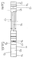
- a channel body 1 is provided with a cover grate 2, in the example shown with a web grate, the Web grating in the channel body 1 protruding locking bracket 4.
- the locking brackets 4 have inward, angled legs 5 at their lower end.
- the web grate is punched out in one piece and formed by folding, the locking brackets 4 and the angled legs 5 being formed by appropriate folding.
- the channel body 1 has in its side walls 3 substantially opposite recesses 6 for receiving a leaf-shaped cover grating locking spring 10.
- the leaf-shaped cover grating locking spring 10 has lateral, oppositely arranged projections 11 which engage in the recesses 6 of the side walls 3 of the channel body 1.
- the cover grating locking spring 10 has at least 2 mirror-symmetrically designed spring legs 12 which are executed toward the inside of the channel body 1 and towards the locking brackets 4 and which are spaced apart from the inside of the side walls 3 so that the locking brackets 4 of the cover grating 2 can reach behind them.
- the spring legs 12 each have an undercut 13, which serve to receive the inwardly angled leg 5 of the respective locking bracket 4.
- the angled leg 5 of the locking bracket 4 lies with its top against the underside of the undercut part 13 of the spring leg 12 over as large an area as possible, so that a secure attachment of the cover grate is ensured.
- the spring legs 12 of the leaf-shaped cover grating locking spring 10 also each have an inlet slope 14.
- the part of the cover grill locking spring 10 forming the inlet slope 14 can be moved away from the angled leg 5 of the locking bracket 4, whereby the locking bracket 4 in question and the grate are exposed initially starting from one side or can be removed simultaneously from two sides with a corresponding force.
- the grate can be unlocked by an upward pulling force.
- the insertion and locking of the cover grate 2, which has the above-mentioned preferably integrally formed locking bracket 4 with inwardly angled legs 5, is done by applying pressure to the grille 2 by sliding the angled legs 5 along the inlet slopes 14 until the spring legs relax Location of the undercut 13 is moved.
- connection area 15 has a stamped-in longitudinal bead 16 in part of the connection area 15, on the one hand to improve the spring properties and on the other hand to increase the stability when the connection area 15 as a handle and assembly aid when laying Channel bodies 1 with cover grating locking spring 10 already in use is used.
- the recesses 6 in the side walls 3 of the channel body 1 preferably have an approximately rectangular or square cross-section, as a result of which the grating locking spring 10 is positioned against rotation.
- the recesses 6 are designed as through openings in the side walls 3 of the channel body 1, can be from the outside with the help of a tool, for. B. screwdriver, pressure on the exposed side of the projections 11 or between the spring leg and the gutter side wall, whereby the spring is pushed out of its seat in the side walls 3, removed from the opposite recess and can be removed from the channel body 1.
- a tool for. B. screwdriver
- the cutouts 6 in the side walls 3 of the channel body 1 can be designed to be flared outwards.
- the connecting region 15 of the sheet-shaped cover grating locking spring 10 has an angled section 18, which is provided on both sides, as a result of which the cover grating locking spring 10 not only on the upper edge of the respective recess 6 but also on part of the inside or inner wall of the respective side wall 3 of the channel body 1 abuts. This improves the fit of the grating locking spring 10 and prevents the same from being pressed out undesirably.
- the cover grate (2) shown in FIG. 1 is designed as a web grate and has a double rebate surface (20) for its respective longitudinal sides.
- the double rebate surface (20) which integrally into the locking bracket (4) with the angled leg portion (5) so that the web grate provided with the required locking brackets (4) can be formed in a single punching and bending process, which increases the manufacturing costs for such a rust can be significantly reduced. In particular, no screw or other connections are required to attach the locking bracket.
- a second exemplary embodiment of the invention according to FIG. 2 shows the arrangement of a cast grate 2 locked in the channel body 1.
- the cast grate 2 has adequate locking brackets 4 with corresponding angled legs 5.
- the design of the cover grate locking spring 10 according to FIG. 2 corresponds and 3 of those as explained with reference to FIG. 1.
- Fig. 3 shows a third embodiment of the drainage channel consisting of a channel body 1 and cover grate 2, the latter being designed as a mesh grate and also has locking bracket 4 and angled legs 5.
- part of the grate frame is assigned the function of the locking bracket 4 with angled legs 5, so that in this case too, the mesh grating 2 on the channel body 1 or the side walls 3 of the channel body 3 can be securely locked without constructive changes to the cover locking spring 10 1 can be achieved.
- the grating locking spring 10 used in the exemplary embodiments will be explained in more detail with reference to a top view and a side view.
- FIG. 4a a taper 17 in the connection area 15 of the cover grate locking spring 10 and the design of the longitudinal bead 16 can be seen.
- the top view according to FIG. 4 a further shows the spring leg 12 with the bevel 14 and the undercut section 13.
- the cover grating locking spring 10 made of stainless spring steel with a rolling strength of the starting material in the range from 1350 to 1500 N / mm 2 is used.
- transition area between the undercut 13 and the inlet slope 14 of the spring leg 12 of the cover grating locking spring 10 can be used as a latching lug, which interacts with a corresponding recess in the leg of the locking bracket 4.
- the formation of an inwardly angled leg 5 is not absolutely necessary.
Applications Claiming Priority (4)
| Application Number | Priority Date | Filing Date | Title |
|---|---|---|---|
| DE4446105 | 1994-12-22 | ||
| DE4446105 | 1994-12-22 | ||
| DE19504869 | 1995-02-14 | ||
| DE19504869A DE19504869C1 (de) | 1995-02-14 | 1995-02-14 | Entwässerungsrinne mit einem ein im wesentlichen U-förmiges Profil aufweisenden Rinnenkörper |
Publications (3)
| Publication Number | Publication Date |
|---|---|
| EP0718446A2 true EP0718446A2 (fr) | 1996-06-26 |
| EP0718446A3 EP0718446A3 (fr) | 1996-11-27 |
| EP0718446B1 EP0718446B1 (fr) | 1998-04-15 |
Family
ID=25943204
Family Applications (1)
| Application Number | Title | Priority Date | Filing Date |
|---|---|---|---|
| EP95118480A Expired - Lifetime EP0718446B1 (fr) | 1994-12-22 | 1995-11-23 | Caniveau d'écoulement avec un corps ayant un profilé essentiellement en forme de "U" |
Country Status (6)
| Country | Link |
|---|---|
| EP (1) | EP0718446B1 (fr) |
| AT (1) | ATE165132T1 (fr) |
| CZ (1) | CZ335295A3 (fr) |
| DE (1) | DE59501904D1 (fr) |
| ES (1) | ES2116665T3 (fr) |
| PL (1) | PL178178B1 (fr) |
Cited By (6)
| Publication number | Priority date | Publication date | Assignee | Title |
|---|---|---|---|---|
| DE29703760U1 (de) * | 1997-02-03 | 1997-05-22 | Coelan Chemie Produktionsgesel | Befestigungsvorrichtung für Schachtdeckel |
| EP0886014A2 (fr) | 1997-06-18 | 1998-12-23 | MEA MEISINGER Stahl und Kunststoff GmbH | Dispositif de drainage superficiel |
| GB2351992A (en) * | 1999-07-16 | 2001-01-17 | Aco Technologies Plc | Drainage channels |
| WO2004113632A1 (fr) * | 2003-06-25 | 2004-12-29 | Aco Severin Ahlmann Gmbh & Co. Kg | Dispositif d'evacuation des eaux de ruissellement |
| EP1627969A3 (fr) * | 2004-08-16 | 2006-08-23 | GRIDIRON SpA | Grille de recouvrement pour un caniveau d'écoulement |
| CN108204032A (zh) * | 2018-01-10 | 2018-06-26 | 广州犀鸟工业设计有限公司 | 一种改进型地漏 |
Families Citing this family (1)
| Publication number | Priority date | Publication date | Assignee | Title |
|---|---|---|---|---|
| CN114412089B (zh) * | 2021-12-27 | 2023-08-08 | 安徽开盛津城建设有限公司 | 一种屋面防水系统 |
Citations (1)
| Publication number | Priority date | Publication date | Assignee | Title |
|---|---|---|---|---|
| CH681313A5 (en) | 1991-11-15 | 1993-02-26 | Hestag Bauelemente | Drainage gutter in concrete slab - has bolted angle-pieces bridging joins between sections and containing elongated holes |
Family Cites Families (1)
| Publication number | Priority date | Publication date | Assignee | Title |
|---|---|---|---|---|
| DE8810154U1 (fr) * | 1988-08-10 | 1988-09-22 | Hauraton Betonwarenfabrik Gmbh & Co Kg, 7550 Rastatt, De |
-
1995
- 1995-11-23 EP EP95118480A patent/EP0718446B1/fr not_active Expired - Lifetime
- 1995-11-23 DE DE59501904T patent/DE59501904D1/de not_active Expired - Fee Related
- 1995-11-23 ES ES95118480T patent/ES2116665T3/es not_active Expired - Lifetime
- 1995-11-23 AT AT95118480T patent/ATE165132T1/de not_active IP Right Cessation
- 1995-12-18 CZ CZ953352A patent/CZ335295A3/cs unknown
- 1995-12-19 PL PL95311923A patent/PL178178B1/pl not_active IP Right Cessation
Patent Citations (1)
| Publication number | Priority date | Publication date | Assignee | Title |
|---|---|---|---|---|
| CH681313A5 (en) | 1991-11-15 | 1993-02-26 | Hestag Bauelemente | Drainage gutter in concrete slab - has bolted angle-pieces bridging joins between sections and containing elongated holes |
Cited By (9)
| Publication number | Priority date | Publication date | Assignee | Title |
|---|---|---|---|---|
| DE29703760U1 (de) * | 1997-02-03 | 1997-05-22 | Coelan Chemie Produktionsgesel | Befestigungsvorrichtung für Schachtdeckel |
| EP0886014A2 (fr) | 1997-06-18 | 1998-12-23 | MEA MEISINGER Stahl und Kunststoff GmbH | Dispositif de drainage superficiel |
| GB2351992A (en) * | 1999-07-16 | 2001-01-17 | Aco Technologies Plc | Drainage channels |
| GB2351992B (en) * | 1999-07-16 | 2001-05-30 | Aco Technologies Plc | Drainage channels |
| WO2004113632A1 (fr) * | 2003-06-25 | 2004-12-29 | Aco Severin Ahlmann Gmbh & Co. Kg | Dispositif d'evacuation des eaux de ruissellement |
| DE10328612B4 (de) * | 2003-06-25 | 2009-04-09 | Aco Severin Ahlmann Gmbh & Co. Kg | Oberflächenentwässerungseinrichtung |
| US7524133B2 (en) | 2003-06-25 | 2009-04-28 | Aco Severin Ahlmann Gmbh & Co. Kg | Surface water drainage system |
| EP1627969A3 (fr) * | 2004-08-16 | 2006-08-23 | GRIDIRON SpA | Grille de recouvrement pour un caniveau d'écoulement |
| CN108204032A (zh) * | 2018-01-10 | 2018-06-26 | 广州犀鸟工业设计有限公司 | 一种改进型地漏 |
Also Published As
| Publication number | Publication date |
|---|---|
| PL178178B1 (pl) | 2000-03-31 |
| ES2116665T3 (es) | 1998-07-16 |
| EP0718446B1 (fr) | 1998-04-15 |
| EP0718446A3 (fr) | 1996-11-27 |
| PL311923A1 (en) | 1996-06-24 |
| DE59501904D1 (de) | 1998-05-20 |
| CZ335295A3 (en) | 1997-03-12 |
| ATE165132T1 (de) | 1998-05-15 |
Similar Documents
| Publication | Publication Date | Title |
|---|---|---|
| EP1383967B1 (fr) | Couvercle pour un systeme d'ecoulement des eaux | |
| EP1312287A1 (fr) | Dispositif de suspension comprenant un profilé destiné à être monté verticalement et une console pouvant être accrochée à ce profilé | |
| DE202007003060U1 (de) | Verbindungselement | |
| EP0708001A1 (fr) | Dispositif pour le fixation d'un enjoliveur ou d'une moulure de couverture | |
| DE3510461C1 (de) | Befestigung fuer die Lamellen einer Jalousie | |
| DE4121433C1 (fr) | ||
| EP2055888A2 (fr) | Porte dotée d'un joint et joint de porte correspondant | |
| EP0718446B1 (fr) | Caniveau d'écoulement avec un corps ayant un profilé essentiellement en forme de "U" | |
| EP0399955B1 (fr) | Elément de fermeture pour verrouiller un couvercle dans un cadre | |
| DE19504869C1 (de) | Entwässerungsrinne mit einem ein im wesentlichen U-förmiges Profil aufweisenden Rinnenkörper | |
| WO2013087375A1 (fr) | Élément de fixation et grille latérale | |
| DE19511206C2 (de) | Hochbauentwässerungsrinne | |
| EP0687784A1 (fr) | Rigole de drainage pour bâtiments | |
| EP2292861B1 (fr) | Fenêtre de toit d'habitation et procédé de fixation d'une tôle de recouvrement | |
| EP1610980A1 (fr) | Dispositif permettant de fixer a un support un boitier, notamment le boitier de batterie d'un vehicule automobile | |
| EP0805243A2 (fr) | Attache en plusieurs parties pour façades | |
| DE202006004608U1 (de) | Verbindungsanordnung für einen Lamellen aufweisenden Raffstore o.dgl. | |
| DE19521862C2 (de) | Befestigungsvorrichtung für eine Zier- bzw. Abdeckleiste | |
| AT500181B1 (de) | Tür- oder fensterbeschlag | |
| EP3408591B1 (fr) | Dispositif de retenue pour la fixation d'éléments d'habillage sur des radiateurs plats, et radiateur | |
| EP2270403B1 (fr) | Collecteur solaire avec rail de support | |
| DE10130920B4 (de) | Abdeckung für eine Entwässerungseinrichtung | |
| EP3486400A1 (fr) | Sous-construction pour un revêtement de façade et procédé de montage d'une sous-construction | |
| EP0049432B1 (fr) | Faux-plafond à résilles suspendu | |
| DE19903836C2 (de) | Abdeckung für Licht- und/oder Lüftungsschächte sowie Profilstab hierfür |
Legal Events
| Date | Code | Title | Description |
|---|---|---|---|
| PUAI | Public reference made under article 153(3) epc to a published international application that has entered the european phase |
Free format text: ORIGINAL CODE: 0009012 |
|
| AK | Designated contracting states |
Kind code of ref document: A2 Designated state(s): AT BE DE DK ES FR GB NL |
|
| PUAL | Search report despatched |
Free format text: ORIGINAL CODE: 0009013 |
|
| AK | Designated contracting states |
Kind code of ref document: A3 Designated state(s): AT BE DE DK ES FR GB NL |
|
| 17P | Request for examination filed |
Effective date: 19970219 |
|
| GRAG | Despatch of communication of intention to grant |
Free format text: ORIGINAL CODE: EPIDOS AGRA |
|
| 17Q | First examination report despatched |
Effective date: 19970521 |
|
| GRAG | Despatch of communication of intention to grant |
Free format text: ORIGINAL CODE: EPIDOS AGRA |
|
| GRAH | Despatch of communication of intention to grant a patent |
Free format text: ORIGINAL CODE: EPIDOS IGRA |
|
| GRAH | Despatch of communication of intention to grant a patent |
Free format text: ORIGINAL CODE: EPIDOS IGRA |
|
| GRAA | (expected) grant |
Free format text: ORIGINAL CODE: 0009210 |
|
| AK | Designated contracting states |
Kind code of ref document: B1 Designated state(s): AT BE DE DK ES FR GB NL |
|
| PG25 | Lapsed in a contracting state [announced via postgrant information from national office to epo] |
Ref country code: NL Free format text: LAPSE BECAUSE OF FAILURE TO SUBMIT A TRANSLATION OF THE DESCRIPTION OR TO PAY THE FEE WITHIN THE PRESCRIBED TIME-LIMIT Effective date: 19980415 |
|
| REF | Corresponds to: |
Ref document number: 165132 Country of ref document: AT Date of ref document: 19980515 Kind code of ref document: T |
|
| REF | Corresponds to: |
Ref document number: 59501904 Country of ref document: DE Date of ref document: 19980520 |
|
| PG25 | Lapsed in a contracting state [announced via postgrant information from national office to epo] |
Ref country code: DK Free format text: LAPSE BECAUSE OF FAILURE TO SUBMIT A TRANSLATION OF THE DESCRIPTION OR TO PAY THE FEE WITHIN THE PRESCRIBED TIME-LIMIT Effective date: 19980715 |
|
| REG | Reference to a national code |
Ref country code: ES Ref legal event code: FG2A Ref document number: 2116665 Country of ref document: ES Kind code of ref document: T3 |
|
| GBT | Gb: translation of ep patent filed (gb section 77(6)(a)/1977) |
Effective date: 19980713 |
|
| NLV1 | Nl: lapsed or annulled due to failure to fulfill the requirements of art. 29p and 29m of the patents act | ||
| ET | Fr: translation filed | ||
| PG25 | Lapsed in a contracting state [announced via postgrant information from national office to epo] |
Ref country code: AT Free format text: LAPSE BECAUSE OF NON-PAYMENT OF DUE FEES Effective date: 19981123 |
|
| PG25 | Lapsed in a contracting state [announced via postgrant information from national office to epo] |
Ref country code: BE Free format text: LAPSE BECAUSE OF NON-PAYMENT OF DUE FEES Effective date: 19981130 |
|
| PLBE | No opposition filed within time limit |
Free format text: ORIGINAL CODE: 0009261 |
|
| STAA | Information on the status of an ep patent application or granted ep patent |
Free format text: STATUS: NO OPPOSITION FILED WITHIN TIME LIMIT |
|
| 26N | No opposition filed | ||
| BERE | Be: lapsed |
Owner name: ACO SEVERIN AHLMANN G.M.B.H. & CO. K.G. Effective date: 19981130 |
|
| REG | Reference to a national code |
Ref country code: GB Ref legal event code: IF02 |
|
| PGFP | Annual fee paid to national office [announced via postgrant information from national office to epo] |
Ref country code: DE Payment date: 20060130 Year of fee payment: 11 |
|
| PGFP | Annual fee paid to national office [announced via postgrant information from national office to epo] |
Ref country code: ES Payment date: 20061121 Year of fee payment: 12 |
|
| PGFP | Annual fee paid to national office [announced via postgrant information from national office to epo] |
Ref country code: FR Payment date: 20061128 Year of fee payment: 12 |
|
| PG25 | Lapsed in a contracting state [announced via postgrant information from national office to epo] |
Ref country code: DE Free format text: LAPSE BECAUSE OF NON-PAYMENT OF DUE FEES Effective date: 20070601 |
|
| REG | Reference to a national code |
Ref country code: FR Ref legal event code: ST Effective date: 20080930 |
|
| REG | Reference to a national code |
Ref country code: ES Ref legal event code: FD2A Effective date: 20071124 |
|
| PG25 | Lapsed in a contracting state [announced via postgrant information from national office to epo] |
Ref country code: FR Free format text: LAPSE BECAUSE OF NON-PAYMENT OF DUE FEES Effective date: 20071130 Ref country code: ES Free format text: LAPSE BECAUSE OF NON-PAYMENT OF DUE FEES Effective date: 20071124 |
|
| PGFP | Annual fee paid to national office [announced via postgrant information from national office to epo] |
Ref country code: GB Payment date: 20081031 Year of fee payment: 14 |
|
| GBPC | Gb: european patent ceased through non-payment of renewal fee |
Effective date: 20091123 |
|
| PG25 | Lapsed in a contracting state [announced via postgrant information from national office to epo] |
Ref country code: GB Free format text: LAPSE BECAUSE OF NON-PAYMENT OF DUE FEES Effective date: 20091123 |