EP0718446A2 - Drainage channel with a channel body having a substantially U-shaped profile - Google Patents
Drainage channel with a channel body having a substantially U-shaped profile Download PDFInfo
- Publication number
- EP0718446A2 EP0718446A2 EP95118480A EP95118480A EP0718446A2 EP 0718446 A2 EP0718446 A2 EP 0718446A2 EP 95118480 A EP95118480 A EP 95118480A EP 95118480 A EP95118480 A EP 95118480A EP 0718446 A2 EP0718446 A2 EP 0718446A2
- Authority
- EP
- European Patent Office
- Prior art keywords
- locking
- grate
- cover
- spring
- grating
- Prior art date
- Legal status (The legal status is an assumption and is not a legal conclusion. Google has not performed a legal analysis and makes no representation as to the accuracy of the status listed.)
- Granted
Links
Images


Classifications
-
- E—FIXED CONSTRUCTIONS
- E03—WATER SUPPLY; SEWERAGE
- E03F—SEWERS; CESSPOOLS
- E03F5/00—Sewerage structures
- E03F5/04—Gullies inlets, road sinks, floor drains with or without odour seals or sediment traps
- E03F5/06—Gully gratings
-
- E—FIXED CONSTRUCTIONS
- E03—WATER SUPPLY; SEWERAGE
- E03F—SEWERS; CESSPOOLS
- E03F5/00—Sewerage structures
- E03F5/04—Gullies inlets, road sinks, floor drains with or without odour seals or sediment traps
- E03F5/06—Gully gratings
- E03F2005/065—Gully gratings with elastic locking elements
-
- Y—GENERAL TAGGING OF NEW TECHNOLOGICAL DEVELOPMENTS; GENERAL TAGGING OF CROSS-SECTIONAL TECHNOLOGIES SPANNING OVER SEVERAL SECTIONS OF THE IPC; TECHNICAL SUBJECTS COVERED BY FORMER USPC CROSS-REFERENCE ART COLLECTIONS [XRACs] AND DIGESTS
- Y02—TECHNOLOGIES OR APPLICATIONS FOR MITIGATION OR ADAPTATION AGAINST CLIMATE CHANGE
- Y02A—TECHNOLOGIES FOR ADAPTATION TO CLIMATE CHANGE
- Y02A30/00—Adapting or protecting infrastructure or their operation
- Y02A30/60—Planning or developing urban green infrastructure
Definitions
- the invention relates to a drainage channel with an essentially U-shaped profile channel body, a cover grate that can be fastened to the channel body with locking brackets protruding into the channel body with inwardly angled legs and recesses arranged essentially opposite one another in the side walls of the channel body.
- a cover grate for a drainage channel with a clamp holder is already known, at least two clamps arranged on the cover grate being present.
- the clamping bracket By means of the clamping bracket, the cover grids can be pushed into the channel body and can be resiliently locked by means of loosely arranged clamping parts.
- Recesses can be provided with which a clamping spring cooperates, whereby the latching connection is improved.
- a cover grate has a locking bracket with a stiffening flange, the locking bracket including stiffening flange being connected to the cover grating by screws.
- Resilient legs of the bracket which extend downward to the gutter have projections or beads which snap into corresponding recesses or recesses in the gutter when the cover grating is inserted. In this way, the cover grate should on the one hand be kept safe from traffic and on the other hand be easy to remove for cleaning purposes.
- An essential basic idea of the invention is to propose a special cover locking device in which a leaf-shaped grating locking spring with oppositely formed projections engages in recesses in the side walls of the channel body.
- the grating locking spring is held essentially stress-free in the channel body and can be used as an assembly and transport aid.
- the grating locking spring comprises at least two mirror-symmetrical spring legs, which are executed towards the inside of the channel body and towards locking brackets of the grating and each have an undercut and an inlet slope, the grating with its integrally designed locking brackets can have inwardly angled legs, are easily placed on the channel body from above and moved downwards in a snap-in manner.
- the cover grille preferably has integrally formed locking brackets, the inwardly angled legs of which, when the cover grate is inserted into the channel body and overcoming the spring force of the spring legs, slide the cover grate locking spring along the inlet slope and engage the respective undercut while relaxing the spring legs.
- This snap-in provides sufficient security against undesired lifting or loosening of the cover grate, the cover grating being fixed without play in or on the channel body by the spring force of the spring legs.
- the leaf-shaped cover grating locking spring consists of a stainless spring steel, is manufactured separately and can be easily inserted or pressed into the recesses in the side walls of the channel body from above with appropriate adaptation to the respective drainage channel dimensions.
- the width of the connecting area between the projections is tapered and / or provided with a stamped-in longitudinal bead.
- This longitudinal bead also increases the stability in the sense of the desired possibility of serving as a carrying and assembly aid for the channel body.
- the locking force and thus also the unlocking force of the grate can be adjusted.
- the locking spring is removed by means of a screwdriver such that the screwdriver is inserted on one side between the channel wall and spring leg and the spring leg is pressed out of the locking chamber of the channel side wall.
- the locking spring can then be pulled from the opposite locking chamber by coaxial movement.
- the leaf-shaped grating locking spring has in the connection area for forming opposing stop surfaces in relation to the Side walls of the channel body starting from the projections, an angled section directed towards the channel bottom. With this angled section, the spring rests laterally in the area below the cutouts on the side walls of the channel body, so that displacement forces acting upon the insertion of the grate can be absorbed and the fit of the locking spring in the channel body itself can be improved.
- the grating locking spring is made in one piece from a rustproof spring steel material of sufficient rolling strength by rolling, bending or folding as an inexpensive insert.
- cover gratings namely web, cast or mesh gratings, which are provided with corresponding locking brackets with inwardly angled legs, can be used without any fundamental changes to the leaf-shaped cover grate locking spring itself being required.
- a web grating used is designed such that it has double fold surfaces on the longitudinal side in each case for resting on the upper edge of the side walls of the channel body, the lower part of the fold in each case passing into the locking bracket which is executed on the inside of the channel body and which is at its lower end has the inwardly angled leg.
- a drainage channel with a channel body which has an essentially U-shaped profile and which is completed with a cover grating which can be fastened to the channel body, the locking of the grating in the channel body is possible in a particularly simple manner without locking means which require screws or other tools.
- the cover grate is attached to the channel body so that an independent loosening is prevented, but in the case of a necessary removal of the cover grate, for example for cleaning the channel body, this removal can be carried out without special tools.
- a channel body provided with the cover grating locking springs according to the invention can be transported through the connection areas of the springs in the manner of a handle and moved at the installation location, so that the handling when laying such drainage channels is easier.
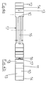
- a channel body 1 is provided with a cover grate 2, in the example shown with a web grate, the Web grating in the channel body 1 protruding locking bracket 4.
- the locking brackets 4 have inward, angled legs 5 at their lower end.
- the web grate is punched out in one piece and formed by folding, the locking brackets 4 and the angled legs 5 being formed by appropriate folding.
- the channel body 1 has in its side walls 3 substantially opposite recesses 6 for receiving a leaf-shaped cover grating locking spring 10.
- the leaf-shaped cover grating locking spring 10 has lateral, oppositely arranged projections 11 which engage in the recesses 6 of the side walls 3 of the channel body 1.
- the cover grating locking spring 10 has at least 2 mirror-symmetrically designed spring legs 12 which are executed toward the inside of the channel body 1 and towards the locking brackets 4 and which are spaced apart from the inside of the side walls 3 so that the locking brackets 4 of the cover grating 2 can reach behind them.
- the spring legs 12 each have an undercut 13, which serve to receive the inwardly angled leg 5 of the respective locking bracket 4.
- the angled leg 5 of the locking bracket 4 lies with its top against the underside of the undercut part 13 of the spring leg 12 over as large an area as possible, so that a secure attachment of the cover grate is ensured.
- the spring legs 12 of the leaf-shaped cover grating locking spring 10 also each have an inlet slope 14.
- the part of the cover grill locking spring 10 forming the inlet slope 14 can be moved away from the angled leg 5 of the locking bracket 4, whereby the locking bracket 4 in question and the grate are exposed initially starting from one side or can be removed simultaneously from two sides with a corresponding force.
- the grate can be unlocked by an upward pulling force.
- the insertion and locking of the cover grate 2, which has the above-mentioned preferably integrally formed locking bracket 4 with inwardly angled legs 5, is done by applying pressure to the grille 2 by sliding the angled legs 5 along the inlet slopes 14 until the spring legs relax Location of the undercut 13 is moved.
- connection area 15 has a stamped-in longitudinal bead 16 in part of the connection area 15, on the one hand to improve the spring properties and on the other hand to increase the stability when the connection area 15 as a handle and assembly aid when laying Channel bodies 1 with cover grating locking spring 10 already in use is used.
- the recesses 6 in the side walls 3 of the channel body 1 preferably have an approximately rectangular or square cross-section, as a result of which the grating locking spring 10 is positioned against rotation.
- the recesses 6 are designed as through openings in the side walls 3 of the channel body 1, can be from the outside with the help of a tool, for. B. screwdriver, pressure on the exposed side of the projections 11 or between the spring leg and the gutter side wall, whereby the spring is pushed out of its seat in the side walls 3, removed from the opposite recess and can be removed from the channel body 1.
- a tool for. B. screwdriver
- the cutouts 6 in the side walls 3 of the channel body 1 can be designed to be flared outwards.
- the connecting region 15 of the sheet-shaped cover grating locking spring 10 has an angled section 18, which is provided on both sides, as a result of which the cover grating locking spring 10 not only on the upper edge of the respective recess 6 but also on part of the inside or inner wall of the respective side wall 3 of the channel body 1 abuts. This improves the fit of the grating locking spring 10 and prevents the same from being pressed out undesirably.
- the cover grate (2) shown in FIG. 1 is designed as a web grate and has a double rebate surface (20) for its respective longitudinal sides.
- the double rebate surface (20) which integrally into the locking bracket (4) with the angled leg portion (5) so that the web grate provided with the required locking brackets (4) can be formed in a single punching and bending process, which increases the manufacturing costs for such a rust can be significantly reduced. In particular, no screw or other connections are required to attach the locking bracket.
- a second exemplary embodiment of the invention according to FIG. 2 shows the arrangement of a cast grate 2 locked in the channel body 1.
- the cast grate 2 has adequate locking brackets 4 with corresponding angled legs 5.
- the design of the cover grate locking spring 10 according to FIG. 2 corresponds and 3 of those as explained with reference to FIG. 1.
- Fig. 3 shows a third embodiment of the drainage channel consisting of a channel body 1 and cover grate 2, the latter being designed as a mesh grate and also has locking bracket 4 and angled legs 5.
- part of the grate frame is assigned the function of the locking bracket 4 with angled legs 5, so that in this case too, the mesh grating 2 on the channel body 1 or the side walls 3 of the channel body 3 can be securely locked without constructive changes to the cover locking spring 10 1 can be achieved.
- the grating locking spring 10 used in the exemplary embodiments will be explained in more detail with reference to a top view and a side view.
- FIG. 4a a taper 17 in the connection area 15 of the cover grate locking spring 10 and the design of the longitudinal bead 16 can be seen.
- the top view according to FIG. 4 a further shows the spring leg 12 with the bevel 14 and the undercut section 13.
- the cover grating locking spring 10 made of stainless spring steel with a rolling strength of the starting material in the range from 1350 to 1500 N / mm 2 is used.
- transition area between the undercut 13 and the inlet slope 14 of the spring leg 12 of the cover grating locking spring 10 can be used as a latching lug, which interacts with a corresponding recess in the leg of the locking bracket 4.
- the formation of an inwardly angled leg 5 is not absolutely necessary.
Abstract
Description
Die Erfindung betrifft eine Entwässerungsrinne mit einem ein im wesentlichen U-förmiges Profil aufweisenden Rinnenkörper, einen am Rinnenkörper befestigbaren Abdeckrost mit in den Rinnenkörper hineinragenden Arretierungsbügeln mit einwärts abgewinkelten Schenkeln sowie in den Seitenwänden des Rinnenkörper im wesentlichen gegenüberliegend angeordneten Aussparungen.The invention relates to a drainage channel with an essentially U-shaped profile channel body, a cover grate that can be fastened to the channel body with locking brackets protruding into the channel body with inwardly angled legs and recesses arranged essentially opposite one another in the side walls of the channel body.
Aus dem deutschen Gebrauchsmuster G 88 10 154.1 ist ein Abdeckrost für eine Entwässerungsrinne mit Klemmhalterung vorbekannt, wobei mindestens zwei am Abdeckrost angeordnete Klemmbügel vorhanden sind. Mittels der Klemmbügel können die Abdeckroste in den Rinnenkörper hineingeschoben und durch versetzt angeordnete lose Klemmteile federnd arretiert werden. Zusätzlich können an den vertikalen Längskanten der Entwässerungsrinne Ausnehmungen vorgesehen sein, mit denen eine Klemmfeder zusammenwirkt, wodurch die Rastverbindung verbessert wird.From the German utility model G 88 10 154.1, a cover grate for a drainage channel with a clamp holder is already known, at least two clamps arranged on the cover grate being present. By means of the clamping bracket, the cover grids can be pushed into the channel body and can be resiliently locked by means of loosely arranged clamping parts. In addition, on the vertical longitudinal edges of the drainage channel Recesses can be provided with which a clamping spring cooperates, whereby the latching connection is improved.
Bei der Entwässerungsrinne gemäß der schweizer Patentschrift CH 681 313 A5 weist ein Abdeckrost einen Arretierungsbügel mit einem Versteifungsflansch auf, wobei der Arretierungsbügel einschließlich Versteifungsflansch durch Schrauben mit dem Abdeckrost verbunden ist.In the drainage channel according to the Swiss patent specification CH 681 313 A5, a cover grate has a locking bracket with a stiffening flange, the locking bracket including stiffening flange being connected to the cover grating by screws.
Federnde nach unten zur Rinne reichende Schenkel des Bügels besitzen Vorsprünge oder Sicken, die beim Einsetzen des Abdeckrostes in entsprechende Ausnehmungen oder Aussparungen der Rinne einschnappen. Hierdurch soll der Abdeckrost einerseits verkehrssicher gehalten und andererseits leicht zu Reinigungszwecken entfernbar sein.Resilient legs of the bracket which extend downward to the gutter have projections or beads which snap into corresponding recesses or recesses in the gutter when the cover grating is inserted. In this way, the cover grate should on the one hand be kept safe from traffic and on the other hand be easy to remove for cleaning purposes.
Es hat sich jedoch gezeigt, daß diese Art der Rostarretierung bei Mineralgußrinnen nicht angewandt werden kann, da die Arretierungsfedern bei häufiger Rostbetätigung die Rinnenwände und Arretierungskammern zerstören würde.It has been shown, however, that this type of grating lock cannot be used with mineral cast channels, since the locking springs would destroy the channel walls and locking chambers if the grate were operated frequently.
Es ist daher Aufgabe der Erfindung eine Entwässerungsrinne mit einem ein im wesentlichen U-förmiges Profil aufweisenden Rinnenkörper und einen am Rinnenkörper befestigbaren Abdeckrost vorzuschlagen, welche eine ausreichende Sicherheit gegen unbeabsichtigtes Lösen des Abdeckrostes bietet und wobei unterschiedliche Abdeckroste in einfacher Weise sicher befestigt werden können, ohne daß sich herstellungs- oder montageseitig höhere Anforderung ergeben.It is therefore an object of the invention to provide a drainage channel with an essentially U-shaped profile channel body and a cover grate that can be attached to the channel body, which offers sufficient security against unintentional loosening of the cover grate and wherein different cover grids can be securely attached in a simple manner without that there are higher requirements on the manufacturing or assembly side.
Die Lösung der Aufgabe der Erfindung erfolgt mit einem Gegenstand gemäß den Merkmalen des Patentanspruches 1, wobei die Unteransprüche mindestens zweckmäßige Ausgestaltungen und Weiterbildungen umfassen.The object of the invention is achieved with an object according to the features of
Ein wesentlicher Grundgedanke der Erfindung besteht darin, eine spezielle Abdeckrostverriegelung vorzuschlagen, bei der eine blattförmig Abdeckrost-Verriegelungsfeder mit gegenüberliegend ausgebildeten Auskragungen in Aussparungen der Seitenwände des Rinnenkörpers eingreift.An essential basic idea of the invention is to propose a special cover locking device in which a leaf-shaped grating locking spring with oppositely formed projections engages in recesses in the side walls of the channel body.
In diesem Zustand wird die Abdeckrost-Verriegelungsfeder im wesentlichen spannungsfrei im Rinnenkörper gehalten und kann als Montage- und Transporthilfe genutzt werden.In this state, the grating locking spring is held essentially stress-free in the channel body and can be used as an assembly and transport aid.
Dadurch, daß gemäß einem weiteren Grundgedanken der Erfindung die Abdeckrost-Verriegelungsfeder mindestens zwei spiegelsymmetrisch ausgebildete, zur Innenseite des Rinnenkörpers und zu Arretierungsbügeln des Abdeckrostes hingerichtete Federschenkel umfaßt, die jeweils eine Hinterschneidung und eine Einlaufschräge aufweisen, kann der Abdeckrost mit seinen integral ausgebildeten Arretierungsbügeln, die einwärts abgewinkelte Schenkel aufweisen, leicht von oben auf den Rinnenkörper aufgesetzt und einrastend nach unten bewegt werden.Characterized in that, according to a further basic idea of the invention, the grating locking spring comprises at least two mirror-symmetrical spring legs, which are executed towards the inside of the channel body and towards locking brackets of the grating and each have an undercut and an inlet slope, the grating with its integrally designed locking brackets can have inwardly angled legs, are easily placed on the channel body from above and moved downwards in a snap-in manner.
Wie bereits erwähnt besitzt der Abdeckrost vorzugsweise integral angeformte Arretierungsbügel, deren einwärts abgewinkelte Schenkel beim Einsetzen des Abdeckrostes in den Rinnenkörper hinein und unter Überwindung der Federkraft der Federschenkel der Abdeckrost-Verriegelungsfeder an der Einlaufschräge entlanggleiten sowie unter Entspannung der Federschenkel in die jeweilige Hinterschneidung einrasten.As already mentioned, the cover grille preferably has integrally formed locking brackets, the inwardly angled legs of which, when the cover grate is inserted into the channel body and overcoming the spring force of the spring legs, slide the cover grate locking spring along the inlet slope and engage the respective undercut while relaxing the spring legs.
Durch dieses Einrasten ist eine ausreichende Sicherheit gegen unerwünschtes Ausheben oder Lösen des Abdeckrostes gegeben, wobei durch die Federkraft der Federschenkel der Abdeckrost spielfrei im bzw. am Rinnenkörper fixiert wird.This snap-in provides sufficient security against undesired lifting or loosening of the cover grate, the cover grating being fixed without play in or on the channel body by the spring force of the spring legs.
Die erfindungsgemäße blattförmige Abdeckrost-Verriegelungsfeder besteht aus einem nicht-rostenden Federstahl, wird separat gefertigt und kann von ihrer Grundkonstruktion her bei entsprechender Anpassung an die jeweilige Entwässerungsrinnenabmaße leicht in die Aussparungen der Seitenwände der Rinnenkörper von oben eingesetzt bzw. eingedrückt werden.The leaf-shaped cover grating locking spring consists of a stainless spring steel, is manufactured separately and can be easily inserted or pressed into the recesses in the side walls of the channel body from above with appropriate adaptation to the respective drainage channel dimensions.
Zur Verbesserung der Federeigenschaften der Abdeckrost-Verriegelungsfeder ist der zwischen den Auskragungen vorhandene Verbindungsbereich in seiner Breite verjüngt und/oder mit einer eingestanzten Längssicke versehen. Diese Längssicke erhöht darüber hinaus die Stabilität im Sinne der gewünschten Möglichkeit, als Trage- und Montagehilfe der Rinnenkörper zu dienen.To improve the spring properties of the grating locking spring, the width of the connecting area between the projections is tapered and / or provided with a stamped-in longitudinal bead. This longitudinal bead also increases the stability in the sense of the desired possibility of serving as a carrying and assembly aid for the channel body.
Durch die Neigung der Verriegelungsflächen am Rost und der Federschenkel zueinander kann die Verriegelungskraft und somit auch die Entriegelungskraft des Rostes eingestellt werden.Due to the inclination of the locking surfaces on the grate and the spring legs relative to one another, the locking force and thus also the unlocking force of the grate can be adjusted.
Bei entsprechender Neigung beider Flächen zueinander ist es möglich, den Rost mittels Rosthaken durch Aufbringung einer Zugkraft nach oben entfernen zu können. Werden die Verriegelungsflächen von Rost und Feder steiler zueinander gestellt, kann der Rost nur durch Wegbiegen der Federschenkel entriegelt werden.With a corresponding inclination of the two surfaces to one another, it is possible to remove the grate by means of grate hooks by applying a tensile force upwards. If the locking surfaces of the grate and spring are set steeper relative to each other, the grate can only be unlocked by bending the spring legs away.
Dazu ist es zweckmäßig, mit einem Schraubendreher durch die Einlauföffnungen des Rostes hindurchzufahren und die Federschenkel seitlich wegzubiegen, um den Rost dann kraftlos nach oben herausnehmen zu können.For this purpose, it is expedient to drive through the inlet openings of the grate with a screwdriver and to bend the spring legs away to the side so that the grate can then be lifted out forcelessly.
Die Verriegelungsfeder wird mittels Schraubendreher dermaßen entfernt, daß der Schraubendreher auf einer Seite zwischen Rinnenwand und Federschenkel eingeführt wird und der Federschenkel aus der Verriegelungskammer der Rinnenseitenwand herausgedrückt wird.The locking spring is removed by means of a screwdriver such that the screwdriver is inserted on one side between the channel wall and spring leg and the spring leg is pressed out of the locking chamber of the channel side wall.
Danach kann die Verriegelungsfeder durch koaxiale Bewegung aus der gegenüberliegenden Verriegelungskammer gezogen werden.The locking spring can then be pulled from the opposite locking chamber by coaxial movement.
In einer Ausgestaltung der Erfindung besitzt die blattförmige Abdeckrost-Verriegelungsfeder im Verbindungsbereich zur Bildung von gegenüberliegenden Anschlagflächen bezogen auf die Seitenwände des Rinnenkörpers ausgehend von den Auskragungen, einen zum Rinnenboden hin gerichteten abgewinkelten Abschnitt. Mit diesem abgewinkelten Abschnitt liegt die Feder seitlich im Bereich unterhalb der Aussparungen an den Seitenwänden des Rinnenkörpers an, wodurch beim Einsetzen des Rostes einwirkende Verschiebekräfte aufgenommen und der Sitz der Verriegelungsfeder im Rinnenkörper selbst verbessert werden kann.In one embodiment of the invention, the leaf-shaped grating locking spring has in the connection area for forming opposing stop surfaces in relation to the Side walls of the channel body starting from the projections, an angled section directed towards the channel bottom. With this angled section, the spring rests laterally in the area below the cutouts on the side walls of the channel body, so that displacement forces acting upon the insertion of the grate can be absorbed and the fit of the locking spring in the channel body itself can be improved.
Vorteilhafterweise ist die Abdeckrost-Verriegelungsfeder einstückig aus einem nicht-rostenden Federstahlmaterial ausreichender Walzfestigkeit mittels Rollen, Biegen oder Abkanten als kostengünstiges Einsatzstück gefertigt.Advantageously, the grating locking spring is made in one piece from a rustproof spring steel material of sufficient rolling strength by rolling, bending or folding as an inexpensive insert.
Im Sinne der Erfindung können unterschiedlichste Abdeckroste, nämlich Steg-, Guß- oder Maschenroste, die mit entsprechenden Arretierungsbügeln mit einwärts abgewinkelten Schenkeln versehen sind, verwendet werden, ohne daß irgendwelche grundsätzlichen Änderungen an der blattförmigen Abdeckrost-Verriegelungsfeder selbst erforderlich sind. Hierdurch ist es möglich, weitgehend standardisierte Rinnenkörper und Abdeckrost-Verriegelungsfedern vorzufertigen und auf Lager zu halten und diese je nach entsprechendem Anwendungs- und Einsatzfall und in Abhängigkeit von der notwendigen Belastungsklasse mit unterschiedlichen Abdeckrosten zu komplettieren.For the purposes of the invention, a wide variety of cover gratings, namely web, cast or mesh gratings, which are provided with corresponding locking brackets with inwardly angled legs, can be used without any fundamental changes to the leaf-shaped cover grate locking spring itself being required. This makes it possible to prefabricate largely standardized gutter bodies and cover grate locking springs and keep them in stock and to complete them with different cover grids depending on the respective application and application and depending on the required load class.
In einer speziellen Ausführungsform ist ein verwendeter Stegrost so ausgebildet, daß dieser jeweils längsseitig Doppelfalzflächen zur Auflage auf die Oberkante der Seitenwände des Rinnenkörpers aufweist, wobei der untere Teil des Falzes jeweils in den zur Innenseite des Rinnenkörper hingerichteten Arretierungsbügel übergeht, der an seinem jeweils unteren Ende den einwärts abgewinkelten Schenkel aufweist.In a special embodiment, a web grating used is designed such that it has double fold surfaces on the longitudinal side in each case for resting on the upper edge of the side walls of the channel body, the lower part of the fold in each case passing into the locking bracket which is executed on the inside of the channel body and which is at its lower end has the inwardly angled leg.
Mittels der Erfindung gelingt es demnach, eine Entwässerungsrinne mit einem ein im wesentlichen U-förmiges Profil aufweisenden Rinnenkörper anzugeben, der mit einem am Rinnenkörper befestigbaren Abdeckrost kompletiert wird, wobei die Verriegelung des Abdeckrostes im Rinnenkörper in besonders einfacher Weise ohne Schraub- oder sonstiges Werkzeug erfordernde Rastmittel möglich ist. Darüber hinaus ist der Abdeckrost am Rinnenkörper so befestigt, daß ein selbständiges Lösen verhindert wird, jedoch im Falle einer erforderlichen Abnahme des Abdeckrostes, beispielsweise zum Reinigen des Rinnenkörpers, dieses Abnehmen ohne Spezialwerkzeug vorgenommen werden kann.By means of the invention it is therefore possible to specify a drainage channel with a channel body which has an essentially U-shaped profile and which is completed with a cover grating which can be fastened to the channel body, the locking of the grating in the channel body is possible in a particularly simple manner without locking means which require screws or other tools. In addition, the cover grate is attached to the channel body so that an independent loosening is prevented, but in the case of a necessary removal of the cover grate, for example for cleaning the channel body, this removal can be carried out without special tools.
Zusätzlich kann ein mit den erfindungsgemäßen Abdeckrost-Verriegelungsfedern versehener Rinnenkörper durch die Verbindungsbereiche der Federn nach Art eines Griffes transportiert und am Montageort bewegt werden, so daß sich die Handhabung beim Verlegen derartig ausgebildeter Entwässerungsrinnen leichter gestaltet.In addition, a channel body provided with the cover grating locking springs according to the invention can be transported through the connection areas of the springs in the manner of a handle and moved at the installation location, so that the handling when laying such drainage channels is easier.
Die Erfindung soll nachstehend anhand eines Ausführungsbeispiels und unter Zuhilfenahme von Figuren näher erläutert werden.The invention will be explained in more detail below using an exemplary embodiment and with the aid of figures.
Hierbei zeigen:
- Fig. 1
- einen Querschnitt durch einen Rinnenkörper mit Abdeckrost-Verriegelungsfedern und arretiertem Stegrost;
- Fig. 2
- einen Querschnitt durch einen Rinnenkörper mit verriegeltem Gußrost;
- Fig. 3
- einen Querschnitt durch einen Rinnenkörper mit verriegeltem Maschenrost und
- Fig. 4a, b
- eine Drauf- bzw. Seitenansicht einer Abdeckrost-Verriegelungsfeder aus einem nicht-rostenden Federstahlmaterial.
- Fig. 1
- a cross section through a channel body with grating locking springs and locked web grating;
- Fig. 2
- a cross section through a channel body with locked cast grate;
- Fig. 3
- a cross section through a channel body with locked mesh and
- 4a, b
- a top and side view of a grate locking spring made of a stainless spring steel material.
Gemäß Fig. 1 ist ein Rinnenkörper 1 mit einem Abdeckrost 2, im gezeigten Beispiel mit einem Stegrost versehen, wobei der Stegrost in den Rinnenkörper 1 hineinragende Arretierungsbügel 4 aufweist. Die Arretierungsbügel 4 weisen an ihrem unteren Ende einwärts gerichtete, abgewinkelte Schenkel 5 auf.1, a
Beim ersten Ausführungsbeispiel wird der Stegrost einstückig ausgestanzt und durch Falzen geformt, wobei die Arretierungsbügel 4 und die abgewinkelten Schenkel 5 durch entsprechendes Abkanten ausgebildet werden.In the first embodiment, the web grate is punched out in one piece and formed by folding, the
Der Rinnenkörper 1 besitzt in seinen Seitenwänden 3 im wesentlichen gegenüberliegende Aussparungen 6 zur Aufnahme einer blattförmigen Abdeckrost-Verriegelungsfeder 10. Die blattförmige Abdeckrost-Verriegelungsfeder 10 weist seitliche, gegenüberliegend angeordnete Auskragungen 11 auf, die in die Aussparungen 6 der Seitenwände 3 des Rinnenkörpers 1 eingreifen.The
Die Abdeckrost-Verriegelungsfeder 10 besitzt mindestens 2 spiegelsymmetrisch ausgebildete, zur Innenseite des Rinnenkörpers 1 und zu den Arretierungsbügeln 4 hingerichtete Federschenkel 12, die von der Innenseite der Seitenwände 3 so beabstandet sind, daß die Arretierungsbügel 4 des Abdeckrostes 2 dahintergreifen können. Die Federschenkel 12 weisen jeweils eine Hinterschneidung 13 auf, die der Aufnahme des einwärts abgewinkelten Schenkels 5 des jeweiligen Arretierungsbügels 4 dienen. Im arretierten Zustand des Abdeckrostes 2 liegt der abgewinkelte Schenkel 5 des Arretierungsbügels 4 mit seiner Oberseite an der Unterseite des Hinterschneidungsteils 13 des Federschenkels 12 möglichst großflächig an, so daß eine sichere Befestigung des Abdeckrostes gewährleistet ist.The cover
Die Federschenkel 12 der blattförmigen Abdeckrost-Verriegelungsfeder 10 besitzen weiterhin je eine Einlaufschräge 14.The
Beim Aufsetzen und Eindrücken des Abdeckrostes 2 von oben in den Rinnenkörper 1 drückt der abgewinkelte Schenkel 5 des Arretierungsbügels 4 auf die Einlaufschräge 14 des Federschenkels 12 und bewegt diesen in Pfeilrichtung so lange, bis der Bereich der Hinterschneidung 13 erreicht ist und der entsprechende Teil der Abdeckrost-Verriegelungsfeder 10 zurückschnappt, wodurch der abgewinkelte Schenkel 5 lagefixiert ist.When the
Durch Ausübung einer Druckkraft von oben auf die Einlaufschräge 14, zweckmäßigerweise durch eine Wassereinlauföffnung im Abdeckrost 2, kann der die Einlaufschräge 14 bildende Teil der Abdeckrost-Verriegelungsfeder 10 vom abgewinkelten Schenkel 5 des Arretierungsbügels 4 wegbewegt werden, wodurch der betreffende Arretierungsbügel 4 freiliegt und der Rost zunächst von einer Seite beginnend oder bei einer entsprechenden Krafteinwirkung von zwei Seiten gleichzeitig nach oben entnommen werden kann. Alternativ ist ein Entriegeln des Rostes durch eine nach oben gerichtete Zugkraft möglich.By exerting a pressure force from above onto the
Das Einsetzen und Arretieren des Abdeckrostes 2, der die erwähnten vorzugsweise integral angeformten Arretierungsbügel 4 mit einwärts abgewinkelten Schenkeln 5 aufweist, erfolgt dadurch, daß mit Druckausübung auf den Abdeckrost 2 dieser durch Gleitbewegung der abgewinkelten Schenkel 5 entlang der Einlaufschrägen 14 bis zur Entspannung der Federschenkel am Ort der Hinterschneidung 13 bewegt wird.The insertion and locking of the
Die blattförmige Abdeckrost-Verriegelungsfeder 10 besitzt beim gezeigten Ausführungsbeispiel gemäß Fig. 1 in einem Teil des Verbindungsbereiches 15 eine eingestanzte Längssicke 16, einerseits zur Verbesserung der Federeigenschaften und andererseits zur Erhöhung der Stabilität dann, wenn der Verbindungsbereich 15 als Tragegriff und Montagehilfe bei der Verlegung von Rinnenkörpern 1 mit bereits eingesetzter Abdeckrost-Verriegelungsfeder 10 genutzt wird.1 has a stamped-in
Die Aussparungen 6 in den Seitenwänden 3 des Rinnenkörpers 1 besitzen vorzugsweise einen annähernd rechteckigen oder quadratischen Querschnitt, wodurch die Abdeckrost-Verriegelungsfeder 10 verdrehsicher positioniert ist.The
In dem Falle, wo die Aussparungen 6 als durchgehende Öffnungen in den Seitenwänden 3 des Rinnenkörpers 1 ausgeführt sind, kann von außen mit Hilfe eines Werkzeuges, z. B. Schraubendrehers, Druck auf die freiliegende Seite der Auskragungen 11 bzw. zwischen Federschenkel und Rinnenseitenwand ausgeübt werden, wodurch die Feder aus ihrem Sitz in den Seitenwänden 3 herausgedrückt, aus der gegenüberliegenden Aussparung entfernt und aus dem Rinnenkörper 1 entnommen werden kann.In the case where the
Zur Gewährleistung der Federeigenschaften der Abdeckrost-Verriegelungsfeder 10 sind die Aussparungen 6 in den Seitenwänden 3 des Rinnenkörpers 1 nach außen hin konisch erweitert ausbildbar.To ensure the spring properties of the cover grating locking
Bei den Ausführungsbeispielen weist der Verbindungsbereich 15 der blattförmigen Abdeckrost-Verriegelungsfeder 10 einen beidseitig vorhandenen abgewinkelten Abschnitt 18 auf, wodurch die Abdeckrost-Verriegelungsfeder 10 nicht nur an der Oberkante der jeweiligen Aussparung 6 sondern auch an einem Teil der Innenseite bzw. Innenwandung der jeweiligen Seitenwand 3 des Rinnenkörpers 1 anliegt. Hierdurch wird der Sitz der Abdeckrost-Verriegelungsfeder 10 verbessert und ein unerwünschtes Herausdrücken derselben vermieden.In the exemplary embodiments, the connecting
Der in der Figur 1 gezeigte Abdeckrost (2) ist als Stegrost ausgebildet und weist eine Doppelfalzfläche (20) für seine jeweiligen Längsseiten auf. Die Doppelfalzfläche (20), die integral in den Arretierungsbügel (4) mit dem abgewinkelten Schenkelabschnitt (5) über, so daß der mit den erforderlichen Arretierungsbügeln (4) versehene Stegrost in einem einzigen Stanz und Biegevorgang ausgebildet werden kann, wodurch sich die Herstellungkosten für eine derartige Rost erheblich reduzieren lassen. Insbesondere sind keinerlei Schraub- oder sonstige Verbindungen zur Befestigung von Arretierungsbügel notwendig.The cover grate (2) shown in FIG. 1 is designed as a web grate and has a double rebate surface (20) for its respective longitudinal sides. The double rebate surface (20) which integrally into the locking bracket (4) with the angled leg portion (5) so that the web grate provided with the required locking brackets (4) can be formed in a single punching and bending process, which increases the manufacturing costs for such a rust can be significantly reduced. In particular, no screw or other connections are required to attach the locking bracket.
Ein zweites Ausführungsbeispiel der Erfindung gemäß Fig. 2 zeigt die Anordnung eines im Rinnenkörper 1 verriegelten Gußrostes 2. Der Gußrost 2 besitzt in seiner Wirkung adäquate Arretierungsbügel 4 mit entsprechenden abgewinkelten Schenkeln 5. Im übrigen entspricht die Ausbildung der Abdeckrost-Verriegelungsfeder 10 gemäß Fig. 2 und 3 derjenigen, wie anhand der Fig. 1 erläutert.A second exemplary embodiment of the invention according to FIG. 2 shows the arrangement of a
Fig. 3 zeigt ein drittes Ausführungsbeispiel der Entwässerungsrinne bestehend aus einem Rinnenkörper 1 und Abdeckrost 2, wobei letzterer als Maschenrost ausgebildet ist und ebenfalls Arretierungsbügel 4 und abgewinkelte Schenkel 5 aufweist. Beim dritten Ausführungsbeispiel wird einem Teil des Rostrahmens die Funktion des Arretierungsbügels 4 mit abgewinkelten Schenkeln 5 zugewiesen, so daß auch in diesem Falle ohne konstruktive Veränderungen an der Abdeckrost-Verriegelungsfeder 10 eine sichere Arretierung des Maschenrostes 2 am Rinnenkörper 1 bzw. den Seitenwänden 3 des Rinnenkörpers 1 erreicht werden kann.Fig. 3 shows a third embodiment of the drainage channel consisting of a
Im übrigen entsprechen die in den Fig. 2 und 3 verwendeten Bezugszeichen denjenigen, welche anhand der Fig. 1 bereits erläutert wurden.Otherwise, the reference symbols used in FIGS. 2 and 3 correspond to those which have already been explained with reference to FIG. 1.
Mit Hilfe der Fig. 4a und 4b soll anhand einer Drauf- und einer Seitenansicht die bei den Ausführungsbeispielen verwendete Abdeckrost-Verriegelungsfeder 10 näher erläutert werden.4a and 4b, the
Bei der Draufsicht gemäß Fig. 4a ist eine Verjüngung 17 im Verbindungsbereich 15 der Abdeckrost-Verriegelungsfeder 10 und die Ausbildung der Längssicke 16 zu erkennen. Die Draufsicht gemäß Fig. 4a zeigt weiterhin den Federschenkel 12 mit Einlaufschräge 14 und dem Hinterschneidungsabschnitt 13.4a, a
In der Seitenansicht gemäß Fig. 4b ist die Seitenfläche der Auskragung 11 sowie der abgewinkelte Abschnitt 18 des Verbindungsbereiches 15 sowie der Hinterschneidungsabschnitt 13 der blattförmigen Abdeckrost-Verriegelungsfeder 10 zu erkennen.4b, the side surface of the
Bei den Ausführungsbeispielen wird die Abdeckrost-Verriegelungsfeder 10 aus nicht-rostendem Federstahl mit einer Walzfestigkeit des Ausgangsmaterials im Bereich von 1350 bis 1500 N/mm² verwendet.In the exemplary embodiments, the cover grating locking
In einer figürlich nicht dargestellten weiteren Ausführungsform kann der Übergangsbereich zwischen der Hinterschneidung 13 und der Einlaufschräge 14 des Federschenkels 12 der Abdeckrost-Verriegelungsfeder 10 als Rastnase verwendet werden, die mit einer entsprechenden Aussparung im Schenkel des Arretierungsbügels 4 zusammenwirkt. Bei dieser Ausführungsform ist das Ausbilden eines einwärts abgewinkelten Schenkels 5 nicht zwingend erforderlich.In a further embodiment, not shown in the figures, the transition area between the undercut 13 and the
Allen gezeigten Ausführungsbeispielen ist jedoch gemeinsam, daß eine Abdeckrostverriegelung in einfacher Weise dadurch möglich wird, daß spezielle Abdeckrost-Verriegelungsfedern im Rinnenkörper eingesetzt sind und der Rost über Arretierungsbügel verfügt, mit deren Hilfe ein Einrasten und sicheres Arretieren verschiedenster Typen von Abdeckrosten ohne Verwendung von Spezialwerkzeug realisiert werden kann.All of the exemplary embodiments shown, however, have in common that a cover grate locking is made possible in a simple manner by using special cover grate locking springs in the channel body and the grate having locking brackets, with the aid of which various types of cover grids can be snapped in and securely locked without the use of special tools can be.
- 11
- RinnenkörperChannel body
- 22nd
- AbdeckrostCover grate
- 33rd
- Seitenwände des RinnenkörpersSide walls of the channel body
- 44th
- ArretierungsbügelLocking bracket
- 55
- abgewinkelter Schenkelangled thigh
- 66
- Aussparung im RinnenkörperCut-out in the channel body
- 77
- konischer Verlauf der Aussparungconical shape of the recess
- 1010th
- blattförmige Abdeckrost-Verriegelungsfederleaf-shaped grating locking spring
- 1111
- AuskragungCantilever
- 1212th
- FederschenkelFeather legs
- 1313
- HinterschneidungUndercut
- 1414
- EinlaufschrägeEntry slope
- 1515
-
Verbindungsbereich der Feder 10Connection area of the
spring 10 - 1616
- LängssickeLongitudinal bead
- 1717th
- Verjüngungrejuvenation
- 1818th
- abgewinkelter Abschnitt des Verbindungsbereichsangled section of the connection area
- 2020th
- DoppelfalzflächeDouble fold surface
- 2121
- Oberkante Seitenwände RinnenkörperUpper edge of the side walls of the channel body
Claims (11)
gekennzeichnet durch,
characterized by
dadurch gekennzeichnet, daß ein zwischen den Auskragungen (11) der blattförmigen Abdeckrost-Verriegelungsfeder (10) vorgesehener Verbindungsbereich (15) mindestens teilweise in seiner Breite verjüngt ist und/oder eine eingestanzte Längssicke (16) aufweist.Drainage channel according to claim 1,
characterized in that a connection area (15) provided between the projections (11) of the leaf-shaped cover grating locking spring (10) is at least partially tapered in width and / or has a stamped-in longitudinal bead (16).
dadurch gekennzeichnet, daß der Verbindungsbereich (15) zur Bildung von gegenüberliegenden Anschlagflächen bezogen auf die Seitenwände (3) des Rinnenkörpers (1) ausgehend von den Auskragungen (11) jeweils einen zum Rinnenboden hin gerichteten abgewinkelten Abschnitt (18) aufweist.Drainage channel according to claim 2,
characterized in that the connecting area (15) for forming opposing stop surfaces with respect to the side walls (3) of the channel body (1), starting from the projections (11), has an angled section (18) directed towards the channel bottom.
dadurch gekennzeichnet, daß die in den Seitenwänden (3) des Rinnenkörpers (1) befindlichen Aussparungen (6) durchgängig und nach außen konisch erweitert ausgebildet sind.Drainage channel according to one of claims 1 to 3,
characterized in that the recesses (6) located in the side walls (3) of the channel body (1) are continuous and are flared outwards.
dadurch gekennzeichnet, daß mit in den Rinnenkörper (1) eingesetzten blattförmigen Abdeckrost-Verriegelungsfedern (10) eine Trage- und Montagehilfe gegeben ist.Drainage channel according to one of claims 1 to 4,
characterized in that a carrying and assembly aid is provided with sheet-shaped cover grating locking springs (10) inserted into the channel body (1).
dadurch gekennzeichnet, daß durch Druckausübung auf die Federschenkel (12) der Abdeckrost-Verriegelungsfeder (10) im wesentlichen von oben der abgewinkelte Schenkelteil (5) des jeweiligen Arretierungsbügels (4) aus der Hinterschneidung (13) heraustritt und auf diese Weise der Abdeckrost (2) nach oben entfernbar ist und/oder das durch Zugkraftausübung mittels eines Rosthakens auf den Abdeckrost (2) dieser nach oben entfernbar ist.Drainage channel according to one of claims 1 to 4,
characterized in that by exerting pressure on the spring legs (12) of the cover grate locking spring (10) essentially the angled leg part (5) of the respective locking bracket (4) emerges from the undercut (13) and in this way the cover grate (2nd ) can be removed upwards and / or can be removed upwards by exerting tensile force by means of a grate hook on the cover grate (2).
dadurch gekennzeichnet, daß die Abdeckrost-Verriegelungsfeder (10) einstückig ausgebildet ist und aus einem nicht-rostenden Federstahlmaterial ausreichender Walz- und Biegefestigkeit besteht.Drainage channel according to one of the preceding claims,
characterized in that the grating locking spring (10) is formed in one piece and consists of a non-rusting spring steel material of sufficient rolling and bending strength.
dadurch gekennzeichnet, daß der Abdeckrost (2) als Steg- , Guß-, oder Maschenrost ausgebildet ist.Drainage channels according to one of the preceding claims,
characterized in that the cover grate (2) is designed as a web, cast, or mesh grate.
dadurch gekennzeichnet, daß der Stegrost jeweils Doppelfalzflächen (20) zur Auflage auf die Oberkante (21) der Seitenwände (3) des Rinnenkörpers (1) aufweist, wobei der Falz jeweils in den zur Innnenseite des Rinnenkörpers (1) hin gerichteten Arretierungsbügel (4) übergeht, der an seinem jeweils unteren Ende den einwärts abgewinkelten Schenkel (5) aufweist.Drainage channel according to claim 8,
characterized in that the web grate each has double rebate surfaces (20) for resting on the upper edge (21) of the side walls (3) of the channel body (1), the fold in each case in the locking bracket (4) directed towards the inside of the channel body (1) passes over, which has the inwardly angled leg (5) at its respective lower end.
dadurch gekennzeichnet, daß, im Falle der Verwendung eines Gußrostes als Abdeckrost (2), der Gußrost angeformte Arretierungsbügel (4) mit nach innen abgewinkelten Schenkeln zum Zusammenwirken mit den Verriegelungsfedern (10) aufweist (Fig 2).Drainage channel according to claim 8,
characterized in that, if a cast grate is used as the cover grate (2), the cast grate has molded-on locking brackets (4) with inwardly angled legs for cooperation with the locking springs (10) (Fig. 2).
dadurch gekennzeichnet, daß, im Falle der Verwendung eines Maschenrostes als Abdeckrost (2), der Maschenrost einen Rostrahmen aufweist, wobei ein Teil des Rostrahmens so geformt ist, daß Arretierungsbügel (4) mit abgewinkelten, nach innen gerichteten Schenkeln zum Zusammenwirken mit den Verriegelungsfedern (10) ausgebildet sind.Drainage channel according to claim 8,
characterized in that , if a mesh grating is used as the cover grating (2), the mesh grating has a grating frame, part of the grating frame being shaped in such a way that locking brackets (4) with angled, inwardly directed legs for interacting with the locking springs ( 10) are formed.
Applications Claiming Priority (4)
| Application Number | Priority Date | Filing Date | Title |
|---|---|---|---|
| DE4446105 | 1994-12-22 | ||
| DE4446105 | 1994-12-22 | ||
| DE19504869A DE19504869C1 (en) | 1995-02-14 | 1995-02-14 | Drainage channel with U-shaped profile |
| DE19504869 | 1995-02-14 |
Publications (3)
| Publication Number | Publication Date |
|---|---|
| EP0718446A2 true EP0718446A2 (en) | 1996-06-26 |
| EP0718446A3 EP0718446A3 (en) | 1996-11-27 |
| EP0718446B1 EP0718446B1 (en) | 1998-04-15 |
Family
ID=25943204
Family Applications (1)
| Application Number | Title | Priority Date | Filing Date |
|---|---|---|---|
| EP95118480A Expired - Lifetime EP0718446B1 (en) | 1994-12-22 | 1995-11-23 | Drainage channel with a channel body having a substantially U-shaped profile |
Country Status (6)
| Country | Link |
|---|---|
| EP (1) | EP0718446B1 (en) |
| AT (1) | ATE165132T1 (en) |
| CZ (1) | CZ335295A3 (en) |
| DE (1) | DE59501904D1 (en) |
| ES (1) | ES2116665T3 (en) |
| PL (1) | PL178178B1 (en) |
Cited By (6)
| Publication number | Priority date | Publication date | Assignee | Title |
|---|---|---|---|---|
| DE29703760U1 (en) * | 1997-02-03 | 1997-05-22 | Coelan Chemie Produktionsgesel | Fixing device for manhole covers |
| EP0886014A2 (en) | 1997-06-18 | 1998-12-23 | MEA MEISINGER Stahl und Kunststoff GmbH | Surface drainage device |
| GB2351992A (en) * | 1999-07-16 | 2001-01-17 | Aco Technologies Plc | Drainage channels |
| WO2004113632A1 (en) * | 2003-06-25 | 2004-12-29 | Aco Severin Ahlmann Gmbh & Co. Kg | Surface water drainage system |
| EP1627969A3 (en) * | 2004-08-16 | 2006-08-23 | GRIDIRON SpA | Grating for drain channel |
| CN108204032A (en) * | 2018-01-10 | 2018-06-26 | 广州犀鸟工业设计有限公司 | A kind of improved drain |
Families Citing this family (1)
| Publication number | Priority date | Publication date | Assignee | Title |
|---|---|---|---|---|
| CN114412089B (en) * | 2021-12-27 | 2023-08-08 | 安徽开盛津城建设有限公司 | Roof waterproof system |
Citations (1)
| Publication number | Priority date | Publication date | Assignee | Title |
|---|---|---|---|---|
| CH681313A5 (en) | 1991-11-15 | 1993-02-26 | Hestag Bauelemente | Drainage gutter in concrete slab - has bolted angle-pieces bridging joins between sections and containing elongated holes |
Family Cites Families (1)
| Publication number | Priority date | Publication date | Assignee | Title |
|---|---|---|---|---|
| DE8810154U1 (en) * | 1988-08-10 | 1988-09-22 | Hauraton Betonwarenfabrik Gmbh & Co Kg, 7550 Rastatt, De |
-
1995
- 1995-11-23 AT AT95118480T patent/ATE165132T1/en not_active IP Right Cessation
- 1995-11-23 DE DE59501904T patent/DE59501904D1/en not_active Expired - Fee Related
- 1995-11-23 ES ES95118480T patent/ES2116665T3/en not_active Expired - Lifetime
- 1995-11-23 EP EP95118480A patent/EP0718446B1/en not_active Expired - Lifetime
- 1995-12-18 CZ CZ953352A patent/CZ335295A3/en unknown
- 1995-12-19 PL PL95311923A patent/PL178178B1/en not_active IP Right Cessation
Patent Citations (1)
| Publication number | Priority date | Publication date | Assignee | Title |
|---|---|---|---|---|
| CH681313A5 (en) | 1991-11-15 | 1993-02-26 | Hestag Bauelemente | Drainage gutter in concrete slab - has bolted angle-pieces bridging joins between sections and containing elongated holes |
Cited By (9)
| Publication number | Priority date | Publication date | Assignee | Title |
|---|---|---|---|---|
| DE29703760U1 (en) * | 1997-02-03 | 1997-05-22 | Coelan Chemie Produktionsgesel | Fixing device for manhole covers |
| EP0886014A2 (en) | 1997-06-18 | 1998-12-23 | MEA MEISINGER Stahl und Kunststoff GmbH | Surface drainage device |
| GB2351992A (en) * | 1999-07-16 | 2001-01-17 | Aco Technologies Plc | Drainage channels |
| GB2351992B (en) * | 1999-07-16 | 2001-05-30 | Aco Technologies Plc | Drainage channels |
| WO2004113632A1 (en) * | 2003-06-25 | 2004-12-29 | Aco Severin Ahlmann Gmbh & Co. Kg | Surface water drainage system |
| DE10328612B4 (en) * | 2003-06-25 | 2009-04-09 | Aco Severin Ahlmann Gmbh & Co. Kg | Surface drainage device |
| US7524133B2 (en) | 2003-06-25 | 2009-04-28 | Aco Severin Ahlmann Gmbh & Co. Kg | Surface water drainage system |
| EP1627969A3 (en) * | 2004-08-16 | 2006-08-23 | GRIDIRON SpA | Grating for drain channel |
| CN108204032A (en) * | 2018-01-10 | 2018-06-26 | 广州犀鸟工业设计有限公司 | A kind of improved drain |
Also Published As
| Publication number | Publication date |
|---|---|
| DE59501904D1 (en) | 1998-05-20 |
| PL178178B1 (en) | 2000-03-31 |
| ES2116665T3 (en) | 1998-07-16 |
| PL311923A1 (en) | 1996-06-24 |
| EP0718446A3 (en) | 1996-11-27 |
| EP0718446B1 (en) | 1998-04-15 |
| CZ335295A3 (en) | 1997-03-12 |
| ATE165132T1 (en) | 1998-05-15 |
Similar Documents
| Publication | Publication Date | Title |
|---|---|---|
| EP1383967B1 (en) | Cover for a drainage device | |
| EP1312287A1 (en) | Hanging device with a rail profile to be vertically mounted and a console suspendable therefrom | |
| DE202007003060U1 (en) | connecting element | |
| EP0708001A1 (en) | Trim or cover moulding fastening device | |
| DE3510461C1 (en) | Attachment for the slats of a blind | |
| DE4121433C1 (en) | ||
| EP2055888A2 (en) | Door with seal and door seal for same | |
| EP0718446B1 (en) | Drainage channel with a channel body having a substantially U-shaped profile | |
| EP0399955B1 (en) | Locking element for securing a cover to a frame | |
| DE19504869C1 (en) | Drainage channel with U-shaped profile | |
| WO2013087375A1 (en) | Fastening element and side-rail arrangement | |
| DE19511206C2 (en) | Building drainage channel | |
| EP0687784A1 (en) | Drainage gully for buildings | |
| EP2292861B1 (en) | Residential skylight and method for fixing a covering plate | |
| WO2004085208A1 (en) | Device for fixing a housing, in particular of a motor-vehicle battery, to a support | |
| EP0805243A2 (en) | Multi-part clip for façades | |
| EP1837479A2 (en) | Connection arrangement for venitian blinds or similar | |
| DE19521862C2 (en) | Fastening device for a decorative or cover strip | |
| AT500181B1 (en) | DOOR OR WINDOW FITTING | |
| EP1646756B1 (en) | Connecting system for profiled rails | |
| EP3408591B1 (en) | Holding device for securing trim parts on panel radiators, and radiator | |
| EP2270403B1 (en) | Solar collector with bearing rail | |
| DE10130920B4 (en) | Cover for a drainage device | |
| EP3486400A1 (en) | Substructure of a façade lining and method for mounting a substructure | |
| EP0049432B1 (en) | Suspended grid-panel ceiling |
Legal Events
| Date | Code | Title | Description |
|---|---|---|---|
| PUAI | Public reference made under article 153(3) epc to a published international application that has entered the european phase |
Free format text: ORIGINAL CODE: 0009012 |
|
| AK | Designated contracting states |
Kind code of ref document: A2 Designated state(s): AT BE DE DK ES FR GB NL |
|
| PUAL | Search report despatched |
Free format text: ORIGINAL CODE: 0009013 |
|
| AK | Designated contracting states |
Kind code of ref document: A3 Designated state(s): AT BE DE DK ES FR GB NL |
|
| 17P | Request for examination filed |
Effective date: 19970219 |
|
| GRAG | Despatch of communication of intention to grant |
Free format text: ORIGINAL CODE: EPIDOS AGRA |
|
| 17Q | First examination report despatched |
Effective date: 19970521 |
|
| GRAG | Despatch of communication of intention to grant |
Free format text: ORIGINAL CODE: EPIDOS AGRA |
|
| GRAH | Despatch of communication of intention to grant a patent |
Free format text: ORIGINAL CODE: EPIDOS IGRA |
|
| GRAH | Despatch of communication of intention to grant a patent |
Free format text: ORIGINAL CODE: EPIDOS IGRA |
|
| GRAA | (expected) grant |
Free format text: ORIGINAL CODE: 0009210 |
|
| AK | Designated contracting states |
Kind code of ref document: B1 Designated state(s): AT BE DE DK ES FR GB NL |
|
| PG25 | Lapsed in a contracting state [announced via postgrant information from national office to epo] |
Ref country code: NL Free format text: LAPSE BECAUSE OF FAILURE TO SUBMIT A TRANSLATION OF THE DESCRIPTION OR TO PAY THE FEE WITHIN THE PRESCRIBED TIME-LIMIT Effective date: 19980415 |
|
| REF | Corresponds to: |
Ref document number: 165132 Country of ref document: AT Date of ref document: 19980515 Kind code of ref document: T |
|
| REF | Corresponds to: |
Ref document number: 59501904 Country of ref document: DE Date of ref document: 19980520 |
|
| PG25 | Lapsed in a contracting state [announced via postgrant information from national office to epo] |
Ref country code: DK Free format text: LAPSE BECAUSE OF FAILURE TO SUBMIT A TRANSLATION OF THE DESCRIPTION OR TO PAY THE FEE WITHIN THE PRESCRIBED TIME-LIMIT Effective date: 19980715 |
|
| REG | Reference to a national code |
Ref country code: ES Ref legal event code: FG2A Ref document number: 2116665 Country of ref document: ES Kind code of ref document: T3 |
|
| GBT | Gb: translation of ep patent filed (gb section 77(6)(a)/1977) |
Effective date: 19980713 |
|
| NLV1 | Nl: lapsed or annulled due to failure to fulfill the requirements of art. 29p and 29m of the patents act | ||
| ET | Fr: translation filed | ||
| PG25 | Lapsed in a contracting state [announced via postgrant information from national office to epo] |
Ref country code: AT Free format text: LAPSE BECAUSE OF NON-PAYMENT OF DUE FEES Effective date: 19981123 |
|
| PG25 | Lapsed in a contracting state [announced via postgrant information from national office to epo] |
Ref country code: BE Free format text: LAPSE BECAUSE OF NON-PAYMENT OF DUE FEES Effective date: 19981130 |
|
| PLBE | No opposition filed within time limit |
Free format text: ORIGINAL CODE: 0009261 |
|
| STAA | Information on the status of an ep patent application or granted ep patent |
Free format text: STATUS: NO OPPOSITION FILED WITHIN TIME LIMIT |
|
| 26N | No opposition filed | ||
| BERE | Be: lapsed |
Owner name: ACO SEVERIN AHLMANN G.M.B.H. & CO. K.G. Effective date: 19981130 |
|
| REG | Reference to a national code |
Ref country code: GB Ref legal event code: IF02 |
|
| PGFP | Annual fee paid to national office [announced via postgrant information from national office to epo] |
Ref country code: DE Payment date: 20060130 Year of fee payment: 11 |
|
| PGFP | Annual fee paid to national office [announced via postgrant information from national office to epo] |
Ref country code: ES Payment date: 20061121 Year of fee payment: 12 |
|
| PGFP | Annual fee paid to national office [announced via postgrant information from national office to epo] |
Ref country code: FR Payment date: 20061128 Year of fee payment: 12 |
|
| PG25 | Lapsed in a contracting state [announced via postgrant information from national office to epo] |
Ref country code: DE Free format text: LAPSE BECAUSE OF NON-PAYMENT OF DUE FEES Effective date: 20070601 |
|
| REG | Reference to a national code |
Ref country code: FR Ref legal event code: ST Effective date: 20080930 |
|
| REG | Reference to a national code |
Ref country code: ES Ref legal event code: FD2A Effective date: 20071124 |
|
| PG25 | Lapsed in a contracting state [announced via postgrant information from national office to epo] |
Ref country code: FR Free format text: LAPSE BECAUSE OF NON-PAYMENT OF DUE FEES Effective date: 20071130 Ref country code: ES Free format text: LAPSE BECAUSE OF NON-PAYMENT OF DUE FEES Effective date: 20071124 |
|
| PGFP | Annual fee paid to national office [announced via postgrant information from national office to epo] |
Ref country code: GB Payment date: 20081031 Year of fee payment: 14 |
|
| GBPC | Gb: european patent ceased through non-payment of renewal fee |
Effective date: 20091123 |
|
| PG25 | Lapsed in a contracting state [announced via postgrant information from national office to epo] |
Ref country code: GB Free format text: LAPSE BECAUSE OF NON-PAYMENT OF DUE FEES Effective date: 20091123 |