EP0718172B1 - Lenksäulenanordnung vom teleskopischen Typ - Google Patents
Lenksäulenanordnung vom teleskopischen Typ Download PDFInfo
- Publication number
- EP0718172B1 EP0718172B1 EP95120228A EP95120228A EP0718172B1 EP 0718172 B1 EP0718172 B1 EP 0718172B1 EP 95120228 A EP95120228 A EP 95120228A EP 95120228 A EP95120228 A EP 95120228A EP 0718172 B1 EP0718172 B1 EP 0718172B1
- Authority
- EP
- European Patent Office
- Prior art keywords
- shaft
- column tube
- lock mechanism
- steering wheel
- outer periphery
- Prior art date
- Legal status (The legal status is an assumption and is not a legal conclusion. Google has not performed a legal analysis and makes no representation as to the accuracy of the status listed.)
- Expired - Lifetime
Links
- 230000007246 mechanism Effects 0.000 claims description 56
- 230000035939 shock Effects 0.000 claims description 25
- 238000010276 construction Methods 0.000 description 5
- 230000004048 modification Effects 0.000 description 3
- 238000012986 modification Methods 0.000 description 3
- 238000010521 absorption reaction Methods 0.000 description 1
- 230000000712 assembly Effects 0.000 description 1
- 238000000429 assembly Methods 0.000 description 1
- 238000006243 chemical reaction Methods 0.000 description 1
- 239000007787 solid Substances 0.000 description 1
- 229920003002 synthetic resin Polymers 0.000 description 1
- 239000000057 synthetic resin Substances 0.000 description 1
Images


Classifications
-
- B—PERFORMING OPERATIONS; TRANSPORTING
- B62—LAND VEHICLES FOR TRAVELLING OTHERWISE THAN ON RAILS
- B62D—MOTOR VEHICLES; TRAILERS
- B62D1/00—Steering controls, i.e. means for initiating a change of direction of the vehicle
- B62D1/02—Steering controls, i.e. means for initiating a change of direction of the vehicle vehicle-mounted
- B62D1/16—Steering columns
- B62D1/18—Steering columns yieldable or adjustable, e.g. tiltable
- B62D1/19—Steering columns yieldable or adjustable, e.g. tiltable incorporating energy-absorbing arrangements, e.g. by being yieldable or collapsible
- B62D1/192—Yieldable or collapsible columns
-
- B—PERFORMING OPERATIONS; TRANSPORTING
- B62—LAND VEHICLES FOR TRAVELLING OTHERWISE THAN ON RAILS
- B62D—MOTOR VEHICLES; TRAILERS
- B62D1/00—Steering controls, i.e. means for initiating a change of direction of the vehicle
- B62D1/02—Steering controls, i.e. means for initiating a change of direction of the vehicle vehicle-mounted
- B62D1/16—Steering columns
- B62D1/18—Steering columns yieldable or adjustable, e.g. tiltable
- B62D1/184—Mechanisms for locking columns at selected positions
Definitions
- the present invention relates to a steering shaft assembly of the telescope type according to the preambles of claim 1 and claim 3.
- a generic steering shaft assembly of the telescope type which comprises a lower shaft operatively connected to a steering gear box, an upper shaft telescopically connected to the lower shaft for axial adjustment in such a manner as to restrict relative rotation to the lower shaft and provided thereon with a steering wheel, and a lock mechanism for releasably fastening the upper shaft to the lower shaft at an adjusted position.
- tile upper shaft is in the form of a hollow shaft having a lower end portion formed as a pair of diametrically opposed deformable portions for engagement with an outer periphery of the lower shaft, and the lock mechanism is comprised of a tubular fastening member threaded over the hollow upper shaft.
- the tubular fastening member is formed with a tapered female screw portion in engagement with tapered male screws formed on the deformable portions of the hollow upper shaft.
- an object of the present invention to provide a steering shaft assembly of the telescopic type wherein a shock absorbing mechanism is provided in combination with a lock mechanism in a simple construction.
- a steering shaft assembly of the telescopic type having a lower shaft rotatably supported in place within a stationary lower column tube, an upper shaft rotatably supported in place within an upper column tube axially movably coupled with the lower column tube and provided the reon with a steering wheel, the upper shaft being telescopically connected to the lower shaft in such a manner as to restrict relative rotation to the lower shaft, and a lock mechanism for releasably fastening the upper column tube to the lower column tube at its adjusted position
- the lock mechanism comprises an axially deformable portion integrally formed with one of the column tubes for engagement with an outer periphery of the other column tube and fastening means for releasably fastening the deformable portion of the column tube to the outer periphery of the other column tube at an adjusted position
- a shock absorbing mechanism in combination with the lock mechanism is comprised of the deformable portion of the column tube and abutment means provided on the
- the lock mechanism comprises a pair of diametrically opposed axially deformable portions integrally formed with an upper end of the lower column tube for engagement with an outer periphery of the upper column tube and fastening means for releasably fastening the deformable portions of the lower column tube to the outer periphery of the upper column tube at an adjusted position
- the abutment means of the shock absorbing mechanism comprises a pair of radial hook portions integrally formed with the upper column tube to be abutted against the deformable portions of the lower column tube when applied with an impact acting on the steering wheel.
- a steering shaft assembly of the telescopic type having a tubular lower shaft for connection to a steering gear box at its lower end, a tubular upper shaft telescopically coupled with the lower shaft in such a manner as to restrict relative rotation to the lower shaft and provided thereon with a steering wheel, and a lock mechanism for releasably fastening the upper shaft to the lower shaft at its adjusted position
- the lock mechanism comprises an axially deformable portion integrally formed with one of the lower and upper shafts for engagement with an outer periphery of the other shaft and fastening means for releasably fastening the deformable portion of the shaft to the outer periphery of the other shaft at an adjusted position
- a shock absorbing mechanism in combination with the lock mechanism is comprised of the deformable portion of the shaft arranged to be deformed by abutment against the steering wheel when applied with an impact acting on the steering wheel.
- the lock mechanism comprises a pair of diametrically opposed deformable portions integrally formed with an upper end of the lower shaft for engagement with an outer periphery of the upper shaft and fastening means for releasably fastening the deformable portions of the lower shaft to the outer periphery of the upper shaft at an adjusted position
- the shock absorbing mechanism is comprised of the deformable portions of the lower shaft arranged to be deformed by abutment against the steering wheel when applied with an impact acting on the steering wheel.
- a steering shaft assembly 10 of the telescopic type in accordance with the present invention which includes a lower shaft 11, an upper shaft 12, a lower column tube 13 and an upper column tube 14.
- the lower shaft 11 is in the form of a hollow shaft which is formed with internal axial serration 11a and operatively connected at its lower end to a steering gear box (not shown).
- the upper shaft 12 is in the form of a solid shaft which has a lower end portion formed with external axial serration 12a for slidable engagement with the internal axial serration 11a of lower shaft 11 and an upper end provided thereon with a steering wheel 15.
- the upper shaft 12 is telescopically connected at its lower end portion with the upper end portion of lower shaft 11 for axial adjustment in such a manner as to restrict relative rotation to the lower shaft 11.
- the lower column tube 13 is in the form of a stationary column tube which is anchored at an angle to a portion of a vehicle body structure (not shown).
- the upper column tube 14 is axially movably coupled within the lower column tube 13.
- the lower shaft 11 is rotatably supported at its lower portion by means of a ball bearing which is fixedly mounted within the lower column tube 13, while the upper shaft 12 is rotatably supported at its upper end portion by means of a ball bearing which is fixedly mounted within the upper column tube 14 in such a manner as to restrict axial movement of the upper shaft 12.
- a lock mechanism 10b is provided in combination with and a shock absorbing mechanism 10c at an interconnected portion of the lower and upper column tubes 13 and 14.
- the lock mechanism 10b is comprised of a pair of diametrically opposed axially deformable portions 13a, 13b integrally formed with an upper end portion of lower column tube 13, an annular fastening nut 16 and a manual lever 17.
- the deformable portions 13a and 13b each are formed in a waveform by cutting the upper end portion of lower column tube 13 in a predetermined width and pressing the cut portions in an axial direction.
- the deformable portions 13a and 13b are located within slit portions 13c, 13d formed in the upper end portion of lower column tube 13 and opposed to one another.
- the deformable portions 13a and 13b each are waved from its base end toward its distal end and bent radially inwardly for engagement with the outer periphery of upper column tube 14.
- the waved deformable portions 13a, 13b are formed as tapered male screw portions 13a1, 13b1 the distal ends of which are formed as fastening portions 13a2, 13b2 to be releasably tightened to the outer periphery of upper column tube 14.
- the annular fastening nut 16 is made of synthetic resin and formed at its inner periphery with a tapered female screw 16a for engagement with the male screw portions 13a1, 13b1 of deformable portions 13a, 13b.
- the manual lever 10b is connected to the fastening nut 16 to be operated by a user for positional adjustment of the steering wheel 15.
- the shock absorbing mechanism 10c is comprised of the waved deformable portions 13a, 13b of lower column tube 13 and a pair of radial hook portions 14a, 14b integrally formed with the upper column tube 14 at an intermediate portion thereof.
- the waved deformable portions 13a, 13b of lower column tube 13 are resiliently deformable in a radial direction and plastically deformable in an axial direction along with the waved configuration.
- the radial hook portions 14a, 14b of upper column tuber 14 are placed in the slit portions 13c, 13d of lower column tube 13 and opposed to the distal ends of deformable portions 13a, 13b.
- the reference numeral 18 designates a switch assembly of a light switch, a washer switch and the like.
- the deformable portions 13a, 13b of lower column tube 13 are radially inwardly tightened by the fastening nut 16 to fix the upper column tube 14 at an adjusted position by engagement therewith at their fastening portions 13a2, 13b2.
- the upper column tube 14 is locked to the lower column tube 13 at the adjusted position to restrict axial movement of the upper shaft 12 relative to the lower shaft 11.
- the manual lever 17 is operated by the user to advance the fastening nut 16 downward to radially outwardly expand the fastening portions 13a2, 13b2 of lower column tube 13 as shown in Fig. 3
- the upper column tube 14 is released from the lower column tube 13. In such a released condition, the upper shaft 12 can be axially moved with the upper column tube 14 to adjust the position of the steering wheel 15.
- the manual lever 16 is operated by the user to advance the fastening nut 16 upward so that the deformable portions 13a, 13b of lower column tube 13 are radially inwardly tightened to the outer periphery of upper column tube 14 at their fastening portions 13a2, 13b2.
- the upper column tube 14 is locked to the lower column tube 13 at an adjusted position to restrict axial movement of the upper shaft 12 relative to the lower shaft 11.
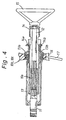
- the upper column tube 14 is moved forward against the tightening force of the fastening nut 16, and in turn, as shown in Fig. 4, the waved deformable portions 13a, 13b of lower column tube 13 are deformed or collapsed in an axial direction by abutment against the hook portions 14a, 14b of upper column tube 14. This causes the shock absorbing mechanism 10c to absorb the impact applied to the steering wheel 10a.
- the lock and shock absorbing mechanisms 10b and 10c can be manufactured in a simple construction.
- the number of the component parts of the lock and shock absorbing mechanisms 10b and 10c can be reduced since the deformable portions 13a, 13b of lower column tube 13 are adapted as the common parts of the lock and shock absorbing mechanisms.
- a reaction force for absorption of the impact can be also adjusted by the configuration of the deformable portions 13a, 13b of lower column tube 13,
- FIG. 5 Illustrated in Fig. 5 is a modification of the shock absorbing mechanism 10c wherein the hook portions 14a, 14b are replaced with a pair of diametrically opposed hook portions 14c, 14d which are waved in cross-section to be deformed in an axial direction when abutted against the deformable portions 13a, 13b of lower column tube 13 due to an impact acting on the steering wheel 15.
- the waved hook portions 14c, 14d are useful to absorb a great impact acting on the steering wheel 15 and to restrict relative rotation of the upper column tube 14 to the lower column tube 13.
- Fig. 6 illustrates another embodiment of a steering shaft assembly 20 in accordance with the present invention which includes a lower shaft 21, an upper shaft 22 and a stationary column tube 23.
- the lower shaft 21 is in the form of a tubular shaft which is formed with large and small diameter portions and connected at its lower end to a steering gear box (not shown).
- the upper shaft 22 is in the form of a tubular shaft of oval cross-section which is formed with a pair of diametrically opposed flat portions 22a, 22b and provided thereon with a steering wheel 25.
- the tubular lower shaft 21 is rotatably supported in place at its large diameter portion by means of a pair of axially spaced ball bearings which are fixedly mounted within the stationary column tube 23.
- the stationary column tube 23 is anchored at angle to a portion of a vehicle body structure (not shown) in the same manner as in the embodiment shown in Fig. 1.
- the tubular upper shaft 22 is axially movably coupled within the tubular lower shaft 21 and releasably fastened to the tubular lower shaft 21 at an adjusted position by means of a lock mechanism 20b.
- the lock mechanism 20b is provided in combination with a shock absorbing mechanism 20c substantially in the same construction as in the embodiment shown in Fig. 1.
- the lock mechanism 20b is comprised of a pair of diametrically opposed axially deformable portions 21a, 21b integrally formed with an upper end portion of tubular lower shaft 21, an annular fastening nut 26 and a manual lever 27.
- the deformable portions 21a, 21b of lower shaft 21 are formed substantially in the same manner as those in the embodiment of Fig. 1, and the fastening nut 26 and manual lever 27 are assembled with the deformable portions 21a, 21b of lower shaft 21 in the same manner as those in the embodiment of Fig. 1.
- the manual lever 27 is operated by a user to advance the fastening nut 26 upward so that the deformable portions 21a, 21b of lower shaft 21 are radially inwardly tightened to the pair of flat portions 22a, 22b of upper shaft 22 at their fastening portions.
- the upper shaft 22 is locked to the lower shaft 21 at an adjusted position to transmit therethrough a steering effort applied to the steering wheel 25 to the lower shaft 21.
- the manual lever 27 is operated to advance the fastening nut 26 downward to radially outwardly expand the deformable portions 21a, 21b of lower shaft 21, the upper shaft 21 is released from the lower shaft 21. In such a released condition, the upper shaft 21 can be axially moved to adjust the position of steering wheel 25.
- the shock absorbing mechanism 20c is comprised of the deformable portions 21a, 21b of lower shaft 21 the distal ends of which are opposed to an annular recess 25a formed in a front end of the steering wheel 25. If the steering wheel 25 is moved forward by an impact applied thereto, the deformable portions 21a, 21b of lower shaft 21 are deformed or collapsed by abutment against the front end of the steering wheel 25 at its annular recess 25a to absorb the impact.
- the steering shaft assembly 20 can be manufactured at a low cost in a more simple construction than the steering shaft assembly shown in Fig. 1.
Landscapes
- Engineering & Computer Science (AREA)
- Chemical & Material Sciences (AREA)
- Combustion & Propulsion (AREA)
- Transportation (AREA)
- Mechanical Engineering (AREA)
- Steering Controls (AREA)
Claims (4)
- Lenkwellenbaugruppe der Teleskopbauart mit einer unteren Welle (11), die an Ort und Stelle innerhalb einer ortsfesten unteren Säulenröhre (13) drehbar gestützt ist, einer oberen Welle (12), die an Ort und Stelle innerhalb einer oberen Wellenröhre (14) drehbar gestützt ist, die mit der unteren Säulenröhre axial bewegbar gekuppelt ist und auf der ein Lenkrad (15) vorgesehen ist, wobei die obere Welle (12) mit der unteren Welle (11) in einer derartigen Weise teleskopartig verbunden ist, daß eine Relativdrehung gegenüber der unteren Welle eingeschränkt ist, und einem Einrastmechanismus (10b) zum lösbaren Feststellen der oberen Säulenrohre (12) an der unteren Säulenröhre (11) in einer eingestellten Position,
dadurch gekennzeichnet, daßder Einrastmechanismus (10b) einen axial verformbaren Abschnitt (13a), der mit einer der Säulenrohren (13) für einen Eingriff mit dem Außenumfang der anderen Säulenröhre (14) einstückig ausgebildet ist, und eine Feststelleinrichtung (16) für ein lösbares Feststellen des verformbaren Abschnittes (13a) der Säulenröhre (13) an dem Außenumfang der anderen Säulenröhre (14) in der eingestellten Position aufweist undein Stoßabsorbiermechanismus (10c) in Kombination mit dem Einrastmechanismus (10b) den verformbaren Abschnitt (13a) der Säulenröhre (13) und eine Anlageeinrichtung (14a), die an der anderen Säulenröhre (14) vorgesehen ist, damit an ihr der verformbare Abschnitt (13a) der Säulenröhre (13) anliegt, wenn auf sie ein auf das Lenkrad (15) wirkender Stoß aufgebracht wird, aufweist. - Lenkwellenbaugruppe gemäß Anspruch 1, wobeider Einrastmechanismus (10b) ein Paar diametrisch entgegengesetzter axial verformbarer Abschnitte (13a 13b), die mit einem oberen Ende der unteren Säulenröhre (13) für einen Eingriff mit einem Außenumfang der oberen Säulenröhre (14) einstückig ausgebildet sind, und eine Feststelleinrichtung (16) zum lösbaren Feststellen der verformbaren Abschnitte (13a, 13b) der unteren Säulenröhre an dem Außenumfang der oberen Säulenröhre (14) in einer eingestellten Position aufweist undein Stoßabsorbiermechanismus (10c) in Kombination mit dem Einrastmechanismus (10b) aus den verformbaren Abschnitten (13a, 13b) der unteren Säulenröhre (13) und einem Paar an radialen Hakenabschnitten (14a, 14b) als Anlageeinrichtung, die mit der oberen Säulenröhre (14) einstückig ausgebildet ist, damit an ihr die verformbaren Abschnitte (13a, 13b) der unteren Säulenröhre anliegen, wenn auf sie ein auf das Lenkrad (15) wirkender Stoß aufgebracht wird, aufweist.
- Lenkwellenbaugruppe der Teleskopbauart mit einer röhrenartigen unteren Welle (21) für eine Verbindung mit einem Lenkgetriebekasten, einer röhrenartigen oberen Welle (22), die mit der unteren Welle (21) in einer derartigen Weise teleskopartig gekuppelt ist, daß eine Relativdrehung gegenüber der unteren Welle eingeschränkt ist, und auf ihr ein Lenkrad (25) vorgesehen ist, und einem Einrastmechanismus (20b) für ein lösbares Feststellen der oberen Welle (22) an der unteren Welle (21) in einer eingestellten Position,
dadurch gekennzeichnet, daßder Einrastmechanismus (20b) einen axial verformbaren Abschnitt (21a), der mit einer Welle (21) aus der Gruppe der oberen und der unteren Welle für einen Eingriff mit einem Außenumfang der anderen Welle (22) einstückig ausgebildet ist, und eine Feststelleinrichtung (26) für ein lösbares Feststellen des verformbaren Abschnittes (21a) der Welle an dem Außenumfang der anderen Welle (22) an einer eingestellten Position aufweist undein Stoßabsorbiermechanismus (20c) in Kombination mit dem Einrastmechanismus (20b) den verformbaren Abschnitt (21) der Welle (21) aufweist, der so angeordnet ist, daß er an dem Lenkrad (25) anliegt, wenn auf sie ein auf das Lenkrad wirkender Stoß aufgebracht wird. - Lenkwellenbaugruppe gemäß Anspruch 3, wobeider Einrastmechanismus (20b) ein Paar diametrisch entgegengesetzter axial verformbarer Abschnitte (21a, 21b), die mit einem oberen Ende der unteren Welle (21) für einen Eingriff mit einem Außenumfang der oberen Welle (22) einstückig ausgebildet sind, und eine Feststelleinrichtung (26) für ein lösbares Feststellen der verformbaren Abschnitte (21a, 21b) der unteren Welle an dem Außenumfang der oberen Welle (22) in einer eingestellten Position aufweist undein Stoßabsorbiermechanismus (20c) in Kombination mit dem Einrastmechanismus (20b) die verformbaren Abschnitte (21a, 21b) der unteren Welle (21) aufweist, die so angeordnet sind, daß sie durch die Anlage an dem Lenkrad (25) verformt werden, wenn auf sie ein auf das Lenkrad wirkender Stoß aufgebracht wird.
Applications Claiming Priority (2)
| Application Number | Priority Date | Filing Date | Title |
|---|---|---|---|
| JP318881/94 | 1994-12-21 | ||
| JP6318881A JPH08175400A (ja) | 1994-12-21 | 1994-12-21 | テレスコピックステアリング装置 |
Publications (2)
| Publication Number | Publication Date |
|---|---|
| EP0718172A1 EP0718172A1 (de) | 1996-06-26 |
| EP0718172B1 true EP0718172B1 (de) | 1999-03-10 |
Family
ID=18104009
Family Applications (1)
| Application Number | Title | Priority Date | Filing Date |
|---|---|---|---|
| EP95120228A Expired - Lifetime EP0718172B1 (de) | 1994-12-21 | 1995-12-20 | Lenksäulenanordnung vom teleskopischen Typ |
Country Status (4)
| Country | Link |
|---|---|
| US (1) | US5634662A (de) |
| EP (1) | EP0718172B1 (de) |
| JP (1) | JPH08175400A (de) |
| DE (1) | DE69508204T2 (de) |
Cited By (1)
| Publication number | Priority date | Publication date | Assignee | Title |
|---|---|---|---|---|
| CN103935392A (zh) * | 2014-05-15 | 2014-07-23 | 广西柳工机械股份有限公司 | 方向机伸缩锁紧机构 |
Families Citing this family (20)
| Publication number | Priority date | Publication date | Assignee | Title |
|---|---|---|---|---|
| US5606892A (en) * | 1995-03-31 | 1997-03-04 | Ford Motor Company | Modular steering column assembly |
| DE19631215C1 (de) * | 1996-08-02 | 1998-01-08 | Mc Micro Compact Car Ag | Stülprohr für Kraftfahrzeuge |
| DE19812179C1 (de) * | 1998-03-19 | 1999-08-19 | Daimler Chrysler Ag | Lenksäulenanordnung für ein Kraftfahrzeug |
| US6099037A (en) * | 1998-10-30 | 2000-08-08 | The Torrington Company | Collapsible shaft having tunable collapse load for motor vehicle |
| KR20010047874A (ko) * | 1999-11-23 | 2001-06-15 | 밍 루 | 자동차용 스티어링 칼럼의 하단부 충격흡수구조 |
| EP1125820B2 (de) * | 2000-02-15 | 2012-07-11 | Nsk Ltd | Lenkung für ein Automobil |
| US6619570B1 (en) | 2000-06-14 | 2003-09-16 | Orbit Irrigation Products, Inc. | Telescoping watering wand |
| GB2368894B (en) * | 2000-11-14 | 2005-07-20 | Nastech Europ Ltd | Steering column assembly for a vehicle |
| DE10141078C1 (de) * | 2001-08-22 | 2003-04-17 | Daimler Chrysler Ag | Sicherheitslenksäule für ein Kraftfahrzeug |
| JP4147579B2 (ja) * | 2002-01-17 | 2008-09-10 | 日本精工株式会社 | ステアリング装置 |
| EP1361137B1 (de) * | 2002-05-07 | 2007-02-14 | ThyssenKrupp Presta AG | Sicherheitslenkung und Betriebsverfahren dafür |
| US7328917B2 (en) * | 2002-05-10 | 2008-02-12 | Nsk Ltd. | Steering device |
| US6729648B2 (en) * | 2002-06-07 | 2004-05-04 | Sealy Technology Llc | Non-linear energy absorbing column assembly |
| JP2007296951A (ja) * | 2006-04-28 | 2007-11-15 | Jtekt Corp | ステアリング装置 |
| JP2009006955A (ja) * | 2007-06-29 | 2009-01-15 | Jtekt Corp | 衝撃吸収式車両用操舵装置 |
| JP5687538B2 (ja) * | 2011-03-28 | 2015-03-18 | 株式会社山田製作所 | ステアリング装置 |
| JP6480177B2 (ja) * | 2014-12-22 | 2019-03-06 | ヒルタ工業株式会社 | ステアリングコラム装置 |
| GB201514096D0 (en) * | 2015-08-10 | 2015-09-23 | Trw Ltd | A Steering Column Assembly |
| JP6627427B2 (ja) * | 2015-10-30 | 2020-01-08 | 日本精工株式会社 | ステアリング装置 |
| CN106004985B (zh) * | 2016-05-26 | 2018-07-03 | 奇瑞汽车股份有限公司 | 一种转向管柱、转向机构及汽车 |
Family Cites Families (9)
| Publication number | Priority date | Publication date | Assignee | Title |
|---|---|---|---|---|
| US3508633A (en) * | 1967-05-17 | 1970-04-28 | Nissan Motor | Plastically deformable impact absorbing means for vehicles |
| US3434367A (en) * | 1967-09-01 | 1969-03-25 | Chrysler Corp | Steering column |
| US4086825A (en) * | 1976-11-18 | 1978-05-02 | Ford Motor Company | Steering column assemblies |
| JPS6036512Y2 (ja) * | 1979-08-10 | 1985-10-30 | アイシン精機株式会社 | ステアリングの軸方向調整装置 |
| US4531619A (en) * | 1982-09-24 | 1985-07-30 | Eckels Robert E | Collapsible steering column |
| JPS60188614A (ja) * | 1984-03-05 | 1985-09-26 | Aisin Seiki Co Ltd | 伸縮自在シヤフト |
| JPS6283246A (ja) * | 1985-10-04 | 1987-04-16 | Aisin Seiki Co Ltd | テレスコピツクステアリング装置 |
| GB2228548A (en) * | 1989-02-22 | 1990-08-29 | Secr Defence | Energy absorbing device |
| ATE133118T1 (de) * | 1992-06-03 | 1996-02-15 | Reiche & Co | Kraftfahrzeuglenksäule |
-
1994
- 1994-12-21 JP JP6318881A patent/JPH08175400A/ja active Pending
-
1995
- 1995-12-19 US US08/574,909 patent/US5634662A/en not_active Expired - Fee Related
- 1995-12-20 DE DE69508204T patent/DE69508204T2/de not_active Expired - Fee Related
- 1995-12-20 EP EP95120228A patent/EP0718172B1/de not_active Expired - Lifetime
Cited By (1)
| Publication number | Priority date | Publication date | Assignee | Title |
|---|---|---|---|---|
| CN103935392A (zh) * | 2014-05-15 | 2014-07-23 | 广西柳工机械股份有限公司 | 方向机伸缩锁紧机构 |
Also Published As
| Publication number | Publication date |
|---|---|
| JPH08175400A (ja) | 1996-07-09 |
| US5634662A (en) | 1997-06-03 |
| DE69508204T2 (de) | 1999-09-30 |
| DE69508204D1 (de) | 1999-04-15 |
| EP0718172A1 (de) | 1996-06-26 |
Similar Documents
| Publication | Publication Date | Title |
|---|---|---|
| EP0718172B1 (de) | Lenksäulenanordnung vom teleskopischen Typ | |
| EP1661789B1 (de) | Positionsverstellungs-lenksäulenvorrichtung für fahrzeuge | |
| US4086825A (en) | Steering column assemblies | |
| US6623036B2 (en) | Steering column assembly for a vehicle | |
| US5845936A (en) | Collapsible outer column formed integral with brackets | |
| CN102119099B (zh) | 转向装置 | |
| US7025380B2 (en) | Power telescopic type steering column | |
| US8091449B2 (en) | Steering apparatus | |
| JP5370520B2 (ja) | ステアリング装置 | |
| WO2012017853A1 (ja) | 衝撃吸収式ステアリング装置 | |
| WO2012017854A1 (ja) | 衝撃吸収式ステアリング装置 | |
| US9919725B2 (en) | Steering column | |
| JP3591284B2 (ja) | チルト式ステアリング装置用ステアリングコラムの揺動支持装置 | |
| GB2113629A (en) | Mounting for an adjustable steering column | |
| JP5338854B2 (ja) | ステアリング装置 | |
| JP2008114837A (ja) | 衝撃吸収式ステアリングコラム装置 | |
| JP2010018182A (ja) | ステアリング装置 | |
| US4299138A (en) | Steering wheel for vehicles | |
| JPH0527338Y2 (de) | ||
| JP6075541B2 (ja) | 車両のステアリング装置 | |
| US20120006141A1 (en) | Steering Wheel Adjustment And Securement Mechanism | |
| KR20150142395A (ko) | 자동차의 조향 컬럼 | |
| JP2007153088A (ja) | ステアリング装置 | |
| JPH0611857Y2 (ja) | テレスコピック・ステアリング装置 | |
| EP0281193B1 (de) | Lenksäule mit elastischen Mitteln zur Beseitigung des Spiels |
Legal Events
| Date | Code | Title | Description |
|---|---|---|---|
| PUAI | Public reference made under article 153(3) epc to a published international application that has entered the european phase |
Free format text: ORIGINAL CODE: 0009012 |
|
| AK | Designated contracting states |
Kind code of ref document: A1 Designated state(s): DE FR GB IT SE |
|
| 17P | Request for examination filed |
Effective date: 19960618 |
|
| 17Q | First examination report despatched |
Effective date: 19970506 |
|
| GRAG | Despatch of communication of intention to grant |
Free format text: ORIGINAL CODE: EPIDOS AGRA |
|
| GRAG | Despatch of communication of intention to grant |
Free format text: ORIGINAL CODE: EPIDOS AGRA |
|
| GRAH | Despatch of communication of intention to grant a patent |
Free format text: ORIGINAL CODE: EPIDOS IGRA |
|
| GRAH | Despatch of communication of intention to grant a patent |
Free format text: ORIGINAL CODE: EPIDOS IGRA |
|
| GRAA | (expected) grant |
Free format text: ORIGINAL CODE: 0009210 |
|
| AK | Designated contracting states |
Kind code of ref document: B1 Designated state(s): DE FR GB IT SE |
|
| ITF | It: translation for a ep patent filed | ||
| REF | Corresponds to: |
Ref document number: 69508204 Country of ref document: DE Date of ref document: 19990415 |
|
| ET | Fr: translation filed | ||
| PGFP | Annual fee paid to national office [announced via postgrant information from national office to epo] |
Ref country code: GB Payment date: 19991214 Year of fee payment: 5 |
|
| PLBE | No opposition filed within time limit |
Free format text: ORIGINAL CODE: 0009261 |
|
| STAA | Information on the status of an ep patent application or granted ep patent |
Free format text: STATUS: NO OPPOSITION FILED WITHIN TIME LIMIT |
|
| 26N | No opposition filed | ||
| PGFP | Annual fee paid to national office [announced via postgrant information from national office to epo] |
Ref country code: SE Payment date: 20001206 Year of fee payment: 6 |
|
| PGFP | Annual fee paid to national office [announced via postgrant information from national office to epo] |
Ref country code: DE Payment date: 20001211 Year of fee payment: 6 |
|
| PGFP | Annual fee paid to national office [announced via postgrant information from national office to epo] |
Ref country code: FR Payment date: 20001212 Year of fee payment: 6 |
|
| PG25 | Lapsed in a contracting state [announced via postgrant information from national office to epo] |
Ref country code: GB Free format text: LAPSE BECAUSE OF NON-PAYMENT OF DUE FEES Effective date: 20001220 |
|
| GBPC | Gb: european patent ceased through non-payment of renewal fee |
Effective date: 20001220 |
|
| PG25 | Lapsed in a contracting state [announced via postgrant information from national office to epo] |
Ref country code: SE Free format text: LAPSE BECAUSE OF NON-PAYMENT OF DUE FEES Effective date: 20011221 |
|
| PG25 | Lapsed in a contracting state [announced via postgrant information from national office to epo] |
Ref country code: DE Free format text: LAPSE BECAUSE OF NON-PAYMENT OF DUE FEES Effective date: 20020702 |
|
| EUG | Se: european patent has lapsed |
Ref document number: 95120228.2 |
|
| PG25 | Lapsed in a contracting state [announced via postgrant information from national office to epo] |
Ref country code: FR Free format text: LAPSE BECAUSE OF NON-PAYMENT OF DUE FEES Effective date: 20020830 |
|
| REG | Reference to a national code |
Ref country code: FR Ref legal event code: ST |
|
| PG25 | Lapsed in a contracting state [announced via postgrant information from national office to epo] |
Ref country code: IT Free format text: LAPSE BECAUSE OF NON-PAYMENT OF DUE FEES;WARNING: LAPSES OF ITALIAN PATENTS WITH EFFECTIVE DATE BEFORE 2007 MAY HAVE OCCURRED AT ANY TIME BEFORE 2007. THE CORRECT EFFECTIVE DATE MAY BE DIFFERENT FROM THE ONE RECORDED. Effective date: 20051220 |