EP0718155B1 - Modulsystem zum Gepäcktransport auf dem Dach eines Kraftfahrzeuges - Google Patents
Modulsystem zum Gepäcktransport auf dem Dach eines Kraftfahrzeuges Download PDFInfo
- Publication number
- EP0718155B1 EP0718155B1 EP95120084A EP95120084A EP0718155B1 EP 0718155 B1 EP0718155 B1 EP 0718155B1 EP 95120084 A EP95120084 A EP 95120084A EP 95120084 A EP95120084 A EP 95120084A EP 0718155 B1 EP0718155 B1 EP 0718155B1
- Authority
- EP
- European Patent Office
- Prior art keywords
- containers
- roof
- motor vehicle
- retention
- longitudinal
- Prior art date
- Legal status (The legal status is an assumption and is not a legal conclusion. Google has not performed a legal analysis and makes no representation as to the accuracy of the status listed.)
- Expired - Lifetime
Links
- 230000014759 maintenance of location Effects 0.000 claims description 17
- 230000008878 coupling Effects 0.000 claims description 7
- 238000010168 coupling process Methods 0.000 claims description 7
- 238000005859 coupling reaction Methods 0.000 claims description 7
- 230000003287 optical effect Effects 0.000 claims description 7
- 238000004873 anchoring Methods 0.000 claims description 4
- 238000006073 displacement reaction Methods 0.000 claims description 2
- 239000000463 material Substances 0.000 claims description 2
- 239000004033 plastic Substances 0.000 claims description 2
- 229920003023 plastic Polymers 0.000 claims description 2
- 229920001343 polytetrafluoroethylene Polymers 0.000 claims description 2
- 230000011664 signaling Effects 0.000 claims description 2
- -1 polytetrafluoroethylene Polymers 0.000 claims 1
- 239000004810 polytetrafluoroethylene Substances 0.000 claims 1
- 230000002829 reductive effect Effects 0.000 description 6
- 230000000670 limiting effect Effects 0.000 description 2
- 239000000446 fuel Substances 0.000 description 1
- 230000001771 impaired effect Effects 0.000 description 1
- 230000009191 jumping Effects 0.000 description 1
- 230000036961 partial effect Effects 0.000 description 1
- 230000000284 resting effect Effects 0.000 description 1
- 230000000717 retained effect Effects 0.000 description 1
Images


Classifications
-
- B—PERFORMING OPERATIONS; TRANSPORTING
- B60—VEHICLES IN GENERAL
- B60R—VEHICLES, VEHICLE FITTINGS, OR VEHICLE PARTS, NOT OTHERWISE PROVIDED FOR
- B60R9/00—Supplementary fittings on vehicle exterior for carrying loads, e.g. luggage, sports gear or the like
- B60R9/04—Carriers associated with vehicle roof
- B60R9/055—Enclosure-type carriers, e.g. containers, boxes
Definitions
- the present invention relates to a system for transporting luggage and the like on the roof of a motor vehicle of the kind defined in the preamble of Claim 1.
- DE-U-92 07 442 discloses a system of this kind, comprising a specially devised replacement roof panel insertable in a corresponding aperture provided in the roof of a motor vehicle.
- the insertable replacement roof panel is shaped so as to define two longitudinal, recessed side channels or guides, and is further provided with a plurality of recessed retaining members.
- a plurality of suitcase-like contai-' ners can be disposed directly onto the replacement roof panel.
- Said containers are each provided with retractable fastening hook members, which are rotatable for engagement with corresponding retaining members of the roof panel.
- the containers in use rest directly in contact with the upper surface or face of said roof panel and any displacement thereof to and from their anchoring positions may endamage (scratch) the roof surface.
- FR-A-2 581 943 discloses a luggage transport or rack system comprising a structure formed by a plurality of transverse load-bearing arches extending at a distance above the roof of the motor vehicle and having their ends fixed to the longitudinal sides of the roof. Two longitudinal side beams are fixed onto said arches. A plurality of T-shaped transverse rails are fixed onto said beams and are adapted to be slidingly engaged by corresponding rails fixed to the lower. or base surface of three suitcase-like containers having a width essentially equal to the width of the vehicle roof.
- DE-A-39 37 244 discloses a luggage container for mounting above the roof of a motor vehicle, incorporating a safety arrangement capable of generating alarm signals for preventing the theft or unauthorised opening of said container.
- the object of the present invention is to provide an improved system for transporting luggage and the like on the roof of a motor vehicle, which system is simple, convenient and reliable to use, and which in the operating state does not appreciably impair the overall aerodynamics of the motor vehicle and thus its performance in terms of fuel consumption and speed, and which is furthermore stylistically integrated in the aesthetic appearance of the motor vehicle as a whole.
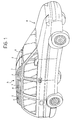
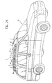
- a motor vehicle is designated M on the roof R of which is mounted a modular system, generally designated S, for transporting luggage and the like.
- this transporting system S comprises three pairs of substantially suitcase-like containers (1, 2), (3, 4) and (5, 6) which are anchored to and are removable from a supporting retention and guide structure secured to the roof R, which will be described in further detail below.
- the containers 1, 3 and 5 have respective shapes which are mirror images of those of the adjacent containers 2, 4 and 6.
- the widths L ( Figure 2) of these containers are substantially less than or equal to half the width of the motor vehicle roof R.
- the containers 1 and 2 of the first pair have an aerodynamic profile which is substantially wedge-shaped.
- the containers of the other two pairs 3, 4 and 5, 6 have shapes which are relatively more squared.
- the containers 1 to 6 have respective handles H on the respective faces which, in the assembled state of use ( Figure 1), are turned towards the body sides of the motor vehicle M.
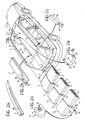
- a retention and guide structure substantially comprising a central profiled portion 7 with a substantially H-shaped section, resting on and secured to the motor vehicle roof R in correspondence with one of its parallel legs. At its sides, this profiled portion 7 defines two substantially symmetrical longitudinal guides or channels 8 (see also Figure 4).
- the retention and guide structure also comprises two further profiled portions 9 which have substantially C-shaped sections and are disposed symmetrically on opposite sides relative to the central profiled portion 7, along the longitudinal sides of the roof.
- the respective longitudinal recesses or guides 10 in the profiled portions 9 face the guides 8 defined in the central profiled portion 7.
- FIGS 2, 3 and 3a show, two pairs of fins 11 and 12 respectively, which are substantially folded in an L-shape and have their free ends directed towards the exterior, are secured to the faces of the containers 1-6 which are to be turned towards the motor vehicle roof R.
- the fins 11 of these containers can be slidingly engaged in the guide grooves 10 of the lateral profiled portions 9 whilst the fins 12 can be slidingly engaged in the guide channels 8 of the central profiled portion 7 (see Figure 4).
- the upper flanges 7a, 9a of the rear ends of the profiled portions can be shortened, as shown in Figure 2 and in the details illustrated in Figures 2b and 2c.
- the front ends of the channels or guides 8, 10 of the profiled portions 7 and 9 respectively are transversely closed, as shown for example in Figure 2a, in order to stop the sliding of the fins 11, 12 of the first pair of containers 1, 2 and to define their stop limit position.
- the containers 1-6 can be disposed adjacent one another on the motor vehicle roof R by engaging the fins 11 and 12 in the guide channels of the profiled portions 7 and 9.
- the containers 3, 4 and 5, 6 advantageously have respective shapes such that, adjacent the containers 1, 2 of the first pair, in the state of use in which they are close to each other (Figure 1), they form an overall volume of aerodynamic shape which is substantially wedge-shaped.
- the arcuate wedge-shaped profile of the first pair of containers 1, 2 enables the overall shape of these containers to be harmoniously and aesthetically combined with the general shape of the motor vehicle M.
- the containers 1-6 can be locked by coupling a suitable locking device indicated 13 in Figures 2, 2d, 5 and 6 to the rear end of the central profiled portion 7.
- the locking device 13 comprises a body 14 having on one face a recess 15 which can be coupled to the rear end portion of the central core 7b of the profiled portion 7 ( Figures 2b, 5 and 6).
- This core 7b is, for example, tubular and has an upper slot-like aperture indicated 16 in Figures 2b, 5 and 6.
- a device with a lock 17, of substantially known type, which can be actuated by means of a key 18 is mounted in the body 14 of the locking device.
- This device comprises a lock cylinder 19 which can rotate about and be moved along an axis which is indicated X-X in Figure 5 and passes through the slot-like aperture 16 when the locking device 13 is coupled to the profiled portion 7.
- a rod 20, into the open end of which a pin 21 is driven, is connected to the cylinder 19.
- Disposed about this rod is a helical spring 22 which, reacting on the one side against a ring 23 secured to the body 14 and on the other against the cylinder 19, tends to oppose the translation of the latter.
- the locking device 13 is coupled to the end portion of the central profiled portion 7, in the manner illustrated in Figure 5, with the cylinder 19 in the extracted state.
- the user can cause the cylinder 19 to move downwards in such a way that the pin 21 of the rod 20 projects beyond the slot-like aperture 16 of the end portion of the core of the profiled portion 7.
- the rotation of the key 18 determines the engagement of the pin 21 below the upper wall of the core 7b of the profiled portion 7.
- the locking device is firmly retained at the rear end of the central profiled portion 7 and its body 14 prevents the containers 1-6 being removed from the profiled portions 7 to 9.
- a microswitch such as the one indicated 24 in Figures 5 and 6, which can be actuated by the end of the pin 21 when the latter is in the locking position shown in Figure 6, can be disposed inside the recess in the tubular core 7b of the central profiled portion 7, adjacent the slot-like aperture 16.
- the microswitch 24 can advantageously be used to generate an electrical signal indicating that the assembly of the containers 1-6 has been locked in position on the motor vehicle roof, it being possible to use this signal, for example, in order to generate a corresponding optical or acoustic signal inside the motor vehicle passenger compartment.
- microswitches can also be used in conjunction with the anti-theft alarm with which the motor vehicle may be equipped in order to determine the generation of an alarm signal when the luggage-transporting containers are in some manner unlawfully removed from the motor vehicle roof whilst the anti-theft system is activated.
- the central profiled portion 7, or the lateral profiled portions 9, can be provided (in a manner not shown) with possible microswitches or other sensors of known type, which can cooperate, for example, with the fins 11 or 12 of the containers 1-6, in order to provide corresponding electrical signals indicating the presence of the containers 1-6 in the respective anchorage positions on the motor vehicle roof.
- These signals can be used, for example, to determine the generation of an acoustic or optical signal inside the motor vehicle passenger compartment and/or can be used in conjunction with the anti-theft alarm system with which the vehicle may be equipped.
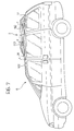
- the modular structure of the transporting system according to the invention enables configurations with reduced carrying capacities to be produced, as shown in Figures 7 and 8.
- the central profiled portion 7 can have an aperture 25 for anchoring a front locking device which is indicated 26 in the same Figure.
- This locking device is also shown in Figures 2e and 7 and is to function as a stop for the front pair of containers 1, 2 in the reduced configuration of the transporting system.
- the front locking device 26 comprises a body 27 through which extend two opposite members 28 and 29 between which a spring 30 tending to urge them in opposite directions is interposed.
- the members 28 and 29 have respective ends which project on the exterior of the body 27 and which can be actuated such that they approach each other, against the action of the spring 30, in the manner of push buttons.
- the members 27, 28 and 29 comprise respective appendages 31, 32 of which the distal ends form respective coupling teeth 33, 34.
- the user presses the push buttons 28 and 29 towards each other, such that their appendages 31, 32 are brought into the approached state.
- the locking device 26 is applied to the front profiled portion 7, such that the coupling teeth 33, 34 extend through the aperture 25, as shown in Figure 9.
- the user then releases the push buttons 28 and 29, which move apart under the action of the spring 30, such that the respective coupling teeth 33 and 34 engage below opposite edge portions of the aperture 25, as shown in Figure 10.
- the front locking device 26 is firmly restrained on the central profiled portion. 7 in order to define the stop position of the pair of front containers 1, 2 in the transporting configuration with reduced capacity.
- the user can then fit these containers 1, 2 and the following pair of containers (for example) 5 and 6 in the profiled portions and lock the assembly formed of these four containers at the rear using the rear locking device 13 described above ( Figure 7).
- the central profiled portion 7 can have a further aperture 35 (Figure 2) enabling the front locking device 26 to be anchored further back, in order to permit the single pair of containers 1 and 2 to be anchored to the profiled portions 7 and 9, as shown in Figure 8, in order to reduce the carrying capacity even further.
- the locking device 26 can be produced in such a way that it can be locked in the anchorage position to the central profiled portion 7 by means of a device having a lock which can be actuated by means of a key.
- the locking device 26 can comprise a shaft 36 rotatably mounted in the body 27, in the area between the members 28 and 29.
- This shaft 36 is advantageously provided with two opposite radial appendages 37 and can be disposed in one angular position ( Figure 9) in which these appendages enable the members 28 and 29 to approach each other to an extent sufficient to enable the locking device to be disengaged from the profiled portion 7 and in a second angular position ( Figure 10) in which this disengagement is prevented.
- the placing of the shaft 36 in the angular position shown in Figure 10 can be controlled by means of a lock and key.
- the transporting system having a modular structure described hitherto has numerous advantages. Firstly, it can assume a plurality of configurations with various carrying capacities, as necessary. In all the possible transporting configurations, the system is nevertheless aesthetically and aerodynamically well-integrated in the general shape of the motor vehicle.
- the individual containers provided in the system are, in fact, suitcases which, in spite of their rather particular shape, are adequately capacious and easy to handle.
- the system according to the invention is advantageously used on both small and large motor vehicles and in particular on those motor vehicles which, when used with the maximum number of occupants permitted, have a limited amount of space available for transporting luggage and the like.
- an optical display panel such as the one indicated 40 in Figure 11, can be disposed inside the motor vehicle passenger compartment.
- This panel comprises a plurality of optical indicators I1-I6 each of which is associated with a corresponding container 1-6.
- a further optical indicator I7 can advantageously be associated with the rear locking device 13.
- the panel 40 can be connected to the motor vehicle check control system, in order to provide the driver with a luminous signal indicating that the containers 1 to 6 are correctly positioned and that the rear locking device 13 has been locked, before the motor vehicle engine is started.
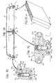
- a central strip secured to the longitudinal centre line of the roof, and two longitudinal side strips 49, adjacent the longitudinal sides of the roof, are applied to the motor vehicle roof R.
- the central strip 47 and the side strips 49 have grooves or channels 50 and 51 respectively on their respective sides.
- first and second guide elements indicated 52 and 53 respectively are coupled to the strips 47 and 49. These guide elements are locked (as will be described below) in respective operating positions along the strips, at distances which are shorter than the lengths of the containers 1 to 6.
- the guide elements 52 anchored to the central strip 47 have a substantially T-shaped section, with respective flanges 52a projecting transversely relative to this strip (see Figures 12a and 15 for example).
- the lower ends of the legs of these guide elements 52 form pairs of fins which face one another, indicated 52b in Figure 15, and which can be slidingly engaged in the channels 50 in the strip 47.
- this strip advantageously has apertures such as those indicated 54 in Figure 15, in which the lower end of a rod 55 displaceably mounted inside the guide element can be engaged.
- the rod 55 is loaded at the top by a helical spring 56 which tends to cause it to protrude at the bottom.
- the rod 55 has an intermediate portion 55a which is substantially conical and which can cooperate with two opposite transverse control rods 57 the ends of which extend in recesses in the flanges 52a of the guide element 52, there forming respective heads 58.
- the user presses the heads 58, causing the rod 55 to withdraw into the body of the guide element 52.
- the user fits the flanges 52b of the guide element into the corresponding channels 50 in the strip 47.
- the guide element is made to slide to the required position and, when this position is reached, the user releases the heads 58 and the rod 55 engages the recess 54 in the strip 47, under the thrust of the spring 56.
- the guide element 52 which is closest the front side of the roof R has a pair of transverse appendages 52c having a stop function, which will be described in greater detail below.
- the guide elements 53 coupled to the side strips 49 are substantially L-shaped with a leg forming a pair of facing appendages 53a which can engage slidingly in the channels 51 in these strips.
- Each element 53 has a respective flange 53b which extends substantially horizontally in the direction of the central strip 47.
- each of the guide elements 53 In order to anchor each of the guide elements 53 in respective predefined portions along the associated strips 49, the latter have respective apertures, such as those indicated 59 in Figure 16.
- the rod 60 has a tapering intermediate portion 60a in which engages a forked end of a balancing device 62 articulated at 63 and having an end 64 which can be manually engaged in correspondence with a notch 65 in the flange 53b of the guide element.
- each guide element 53 is individually coupled to the associated strips 49 whilst the user pressing on the lever 64 determines the lift of the rod 60. In this state, each guide element 53 can be made to slide along the associated strip 49 to the required locking position and, when this position has been reached, the user releases the lever 64 and the spring 61 forces the rod 60 to engage the aperture 59 in the strip.
- the containers 1 to 6 have respective longitudinal side channels, indicated 66 and 67.
- each container 1-6 can be made to slide along the guide elements 53, 52.
- the channel 66 of each container is made to slide on the flanges 53a of the successive guide elements 53 secured to a strip 49 and the channel 67 slides on the flanges 52a of the guide elements 52.
- the first pair of containers 1, 2 thus abuts the transverse fins 52c of the first guide element 52 anchored to the strip 47.
- the first guide elements 53 can also have respective transverse stop appendages, indicated 53c in Figure 12.
- This locking device preferably comprises an appendage 66a ( Figure 12c) which can be introduced into the rear ends of the channels 67 of the pair of rear containers 5, 6.
- the body of the locking device 66 also has a pair of projecting transverse flanges 66b, intended to press against the rear walls of the containers 5, 6, preventing all possibility of their being moved in the longitudinal direction of the motor vehicle.
- the locking device 66 is stably anchored at the rear end of the central strip 47, for example, in the manner shown clearly in Figures 17 and 18.
- the internal structure of the locking device 66 corresponds substantially to that of the locking device 26 described in detail with reference to Figures 9 and 10. A detailed description of Figures 17 and 18 is thus superfluous and will therefore be omitted.
- the modular transporting system can be used in different configurations corresponding to different load capacities.
- the configuration of maximum capacity, in which all the containers 1-6 are used it is thus possible to produce configurations for transportation with reduced capacity with four or two containers alone, substantially as shown in Figures 7 and 8 in relation to the embodiment described above.
- the guide elements 52, 53 can advantageously be removed and placed, for example, inside the motor vehicle and only the strips 49 remain installed on the roof R, causing a visible or aesthetic "disturbance" which is practically negligible.
- sensor means of known type which can provide electrical signals indicating the presence of the containers in the respective anchorage positions provided, can be associated with the strips 47, 49 or with the guide elements 52, 53.
- a position sensor can further be associated with the rear locking device 66.
- the system provides for the use of a given maximum number of pairs of containers of specular form.
- pairs of parallel guides directed transversely to the longitudinal axis of the roof R, are secured thereto.
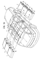
- Figure 19 shows in particular six pairs of guides indicated 101 to 106.
- These guides advantageously consist of a plastics material with a low coefficient of friction, for example polytetrafluoroethylene (Teflon), preferably of a colour corresponding to that of the bodywork of the motor vehicle M.
- Teflon polytetrafluoroethylene
- a strip 70 which forms a hooked retaining member for each of the containers 1 to 6 in predetermined positions on the sides is removably secured along the centre line of the roof R.
- these hooked members are indicated 71-76.
- the hooked members 71-76 extend at a spacing from the surface of the roof R.
- the containers 1 to 6 In the respective faces to be turned towards the roof R, the containers 1 to 6 have respective pairs of parallel channels or grooves 81-86 which can engage in a supporting and sliding manner on the associated guides 101-106 applied to this roof.
- the containers 1-6 In the respective faces to be turned towards the longitudinal axis of the roof R, the containers 1-6 have respective recesses 91-96 ( Figure 19) which can be coupled firmly to the associated hooked members 71-76 carried by the strip 70.
- a locking device which can cooperate with the associated hooked retention member of the strip 70 is accommodated in the recess of each container.
- the containers 1 to 6 can be individually supported on the associated guides 101-106 installed on the sides of the vehicle and thus very conveniently. Furthermore, as will become clearer from the following, these containers can be individually mounted and removed from the roof, with obvious advantages in terms of convenience and practicality of use.
- FIGs 20 and 20a show a possible embodiment of the locking device associated with each container, purely by way of example.
- this device comprises a bolt 97 carried by a shaft 98 which can rotate in a base opening 99 adjacent the base of the container.
- the shaft 98 can be actuated in rotation by means of a lock cylinder 110 which is accessible on the side face of the container which, in its state of use, is turned towards the body side. of the motor vehicle.
- the bolt 97 can be placed in an angular position in which it engages the notch in the hooked member to which the container is coupled (hooked member 73 in Figures 20 and 20a).
- this hooked member in the associated recess in the container prevents the movement of the container in the vertical direction relative to the part.
- the engagement of the bolt 97 in the notch in the hooked member prevents the container uncoupling from this hooked member.
- they can advantageously be provided with resilient pads on their faces to be turned towards the roof R and towards the adjacent containers. Some of these resilient pads are shown in Figure 20 where they are indicated by the reference numerals 111 and 112.
Landscapes
- Engineering & Computer Science (AREA)
- Mechanical Engineering (AREA)
- Fittings On The Vehicle Exterior For Carrying Loads, And Devices For Holding Or Mounting Articles (AREA)
Claims (15)
- System für den Transport von Gepäck und ähnlichem auf dem Dach (R) eines Kraftfahrzeugs (M), wobei das System ein (erstes) Paar von im wesentlichen kofferartigen Behältern (1, 2) enthält, die im wesentlichen spiegelbildlich zueinander ausgebildet sind und eine Breite besitzen, die im wesentlichen schmäler oder gleich der halben Breite des Dachs (R) des Kraftfahrzeugs (M) ist, und die eine im wesentlichen keilförmige, aerodynamische Form besitzen; wobei die Behälter (1, 2) so ausgebildet sind, dass sie an Halterungs/Führungs-Einrichtungen (7, 9, 13, 26; 47, 49, 52, 53; 70-76), die dem Dach (R) zugeordnet sind, in einer Betriebsanordnung abnehmbar verankert werden, in der die Behälter (1, 2) über dem Dach (R) nebeneinander parallel zu den Querseiten des Dachs (R) angeordnet sind;wobei das System dadurch gekennzeichnet ist, dass die Halterungs/Führungs-Einrichtungen (7, 9, 13, 26; 47, 49, 52, 53; 70-76) einen tragenden Aufbau bilden, der vom Dach (R) getrennt und abgesondert ist und dazu dient, um auf der Oberfläche oder Fläche des Dachs (R) so angebracht und befestigt zu werden, dass er zwischen den Behältern (1, 2) und der Oberfläche oder Fläche des Dachs (R) liegt;wobei der Aufbau ein mittleres, längliches Längselement (7; 47; 70) aufweist, das dazu dient, um an der Oberfläche oder Fläche des Dachs (R) befestigt zu werden und an jeder seiner Seiten einen entsprechenden Behälter (1, 2) einzuspannen; sowieeine Vielzahl von seitlichen Halterungs/Führungs-Elementen (9; 49, 53; 101-106) aufweist, die dazu dienen, um die Bewegung der Behälter (1, 2) in und aus ihren Verankerungsstellungen mit einer gleitenden Verschiebung zu ermöglichen, ohne dass die Behälter (1, 2) mit der Oberfläche oder Fläche des Dachs (R) in Berührung gelangen;wobei der Aufbau weiters so erfolgt, dass er eine Vielzahl von Verankerungsstellungen für die Behälter (1, 2) festlegt, die entlang der Längsrichtung des Dachs (R) versetzt sind.
- System gemäß Anspruch 1, dadurch gekennzeichnet, dass das System zumindest ein zweites Paar von Behältern (5, 6) besitzt, die spiegelbildlich ausgebildet sind und eine Breite (L) besitzen, die im wesentlichen schmäler oder gleich der halben Breite des Dachs (R) ist, wobei die Behälter nebeneinander parallel zu den Querseiten des Dachs (R) neben den Hinterflächen der Behälter (1, 2) des ersten Paars angeordnet werden können, wobei sie so ausgebildet sind, dass sie angrenzend aneinander und an die Behälter (1, 2) des ersten Paares einen Raum bilden, der eine im wesentlichen keilförmige, aerodynamische Form besitzt.
- System gemäß Anspruch 2, dadurch gekennzeichnet, dass die Halterungs/Führungs-Einrichtungen (7, 9, 13, 26; 47, 49, 52, 53, 66; 70-76) so ausgebildet sind, dass sie in Längsrichtung des Kraftfahrzeugs (M) eine Vielzahl von aufeinanderfolgenden Verankerungsstellungen für den Aufbau festlegen, der vom ersten und zweiten Paar von Behältern (1, 2; 5, 6) gebildet wird.
- System gemäß irgendeinem der bisherigen Ansprüche, dadurch gekennzeichnet, dass die Behälter (1-6) mit entsprechenden Griffen (H) auf entsprechenden Flächen versehen sind, die im montierten Zustand auf dem Dach (R) zu den Karosserieseiten des Kraftfahrzeugs (M) gerichtet sind.
- System gemäß irgendeinem der bisherigen Ansprüche, dadurch gekennzeichnet, dass eine Fühlereinrichtung, die elektrische Signale liefern kann, die das Vorhandensein der Behälter (1-6) in den Verankerungsstellungen anzeigen, den Halterungs/Führungs-Einrichtungen (7, 9, 13, 26; 47, 49, 52, 53, 66; 70-76) zugeordnet ist.
- System gemäß Anspruch 5, dadurch gekennzeichnet, dass das System weiters eine optische oder akustische Signaleinrichtung (40) enthält, die mit den Signalen gesteuert werden kann, die von der Fühlereinrichtung geliefert werden, um das Vorhandensein der Behälter (1-6) in den entsprechenden vorgegebenen Verankerungsstellungen anzuzeigen.
- System gemäß irgendeinem der bisherigen Ansprüche, dadurch gekennzeichnet, dass die Halterungs/Führungs-Einrichtungen enthalten:einen Profilteil (7) mit einem im wesentlichen H-förmigen Querschnitt, der an der Längsmittelachse des Dachs (R) befestigt werden kann und an seinen Seiten zwei Längskanäle oder Führungen (8) bildet;einen ersten und zweiten C-förmigen Profilteil (9), der entlang der Längsseiten des Dachs (R) befestigt werden kann, wobei die entsprechenden Ausnehmungen (10) zum H-förmigen Profilteil (7) gerichtet sind; und dass jeder Behälter (1-6) entsprechende Seitennasen (11) besitzt, die verschiebbar in einen Kanal oder Führung (10) eines C-förmigen Profilteils (9) sowie in den Kanal oder die Führung (8) des H-förmigen Profilteils eingreifen können.
- System gemäß Anspruch 7, dadurch gekennzeichnet, dass zumindest die Kanäle oder Führungen (8) des H-förmigen Profilteils (7) und/oder jene (10) der C-förmigen Profilteile (9) an jenem Ende, das der Vorderseite des Dachs (R) gegenüberliegt, in Querrichtung verschlossen sind, um die Verschiebung der Behälter (1-6) anzuhalten; wobei es möglich ist, eine erste Verriegelungseinrichtung (13), die verhindern kann, dass die Behälter (1-6) von den Profilteilen (7, 9) entfernt werden, mit dem Hinterende des H-förmigen Profilteils (7) zu kuppeln.
- System gemäß Anspruch 8, dadurch gekennzeichnet, dass das System weiters eine zweite Verriegelungseinrichtung (26) enthält, die in vorgegebenen Zwischenstellungen mit dem H-förmigen Profilteil (7) gekuppelt werden kann, um entsprechende Anschlaggrenzstellungen für das erste Paar von Behältern (1, 2) festzulegen.
- System gemäß irgendeinem der Ansprüche 1 bis 6, dadurch gekennzeichnet, dass die Halterungs/Führungs-Einrichtungen enthalten:eine Mittelleiste (47), die an der Längsmittelachse des Dachs (R) befestigt werden kann und an jeder Seite eine entsprechende Rille (50) besitzt; undeine erste und zweite Seitenleiste (49), die entlang der Längsseiten des Dachs (R) parallel zur Mittelleiste (47) befestigt werden können und an jeder Seite eine entsprechende Rille (51) besitzen;eine Vielzahl von ersten Führungselementen (52), die im wesentlichen T-förmig ausgebildet sind und in den länglichen Seitenrillen (50) in der Mittelleiste (47) verschiebbar gekuppelt und entriegelbar in entsprechenden Betriebsstellungen verriegelt werden können, die entlang dieser Leiste (47) in Abständen angeordnet sind, die kürzer als die Längen dieser Behälter (1-6) sind, wobei die Flansche (52a) der Führungselemente (52) in diesen Betriebsstellungen quer zur Mittelleiste (47) verlaufen; underste und zweite Vielzahl von zweiten Führungselementen (53), die im wesentlichen L-förmig ausgebildet sind und erste Schenkel besitzen, die in die Rillen (51) in einer der Seitenleisten (49) verschiebbar eingreifen können; wobei es möglich ist, die zweiten Führungselemente (53) entriegelbar in entsprechenden Betriebsstellungen zu verriegeln, die in den zugeordneten Seitenleisten (49) in Abständen festgelegt sind, die kürzer als die Längen der Behälter (1-6) sind, wobei ihre zweiten Schenkel (53b) in diesen Stellungen quer in Richtung der Mittelleiste (47) verlaufen;wobei die Behälter (1-6) entsprechende parallele, längliche Seitenkanäle (66, 67) besitzen, die mit den Flanschen (52a) bzw. mit den zweiten Schenkeln (53b) der ersten bzw. zweiten Führungselemente (52, 53) verschiebbar gekuppelt werden können;wobei zumindest eines der ersten Führungselemente (52) und/oder zumindest ein Paar der zweiten Führungselemente (53) so aufgebaut sind, dass sie Anschlagflächen besitzen, um Anschlaggrenzstellungen für das erste Paar von Behältern (1, 2) festzulegen.
- System gemäß Anspruch 10, dadurch gekennzeichnet, dass das System weiters eine Verriegelungseinrichtung (66) enthält, die mit den Leisten (47, 49), im besonderen mit der Mittelleiste (47), gekuppelt werden kann, um das Entfernen der Behälter (1-6) aus den Führungselementen (52, 53) zu verhindern.
- System gemäß irgendeinem der Ansprüche 1 bis 6, dadurch gekennzeichnet, dass die Halterungs/Führungs-Einrichtungen enthalten:zumindest eine erste und zweite Gruppe von Führungen (101-106), die am Dach (R) in entsprechenden parallelen Richtungen quer zur Längsachse des Dachs (R) befestigt werden; undeine Vielzahl von Paaren von Halterungseinrichtungen (71, 72; 73, 74; 75, 76), die an entsprechenden vorgegebenen Stellungen entlang der Längsmittelachse des Dachs (R) befestigt werden; und dass die Behälter (1-6) in der entsprechenden Fläche, die zum Dach (R) gerichtet ist, entsprechende Vielzahlen von parallelen Kanälen oder Rillen (81-86) besitzen, die haltend und gleitend in die Führungen (101-106) einer jeden Gruppe von Führungen eingreifen können, wobei sie in der entsprechenden Fläche, die zur Längsachse des Dachs (R) gerichtet ist, eine entsprechende Verriegelungs/Kupplungs-Einrichtung (97, 98) enthalten, die mit einer der Halterungseinrichtungen (71-76) gekuppelt werden kann.
- System gemäß Anspruch 12, dadurch gekennzeichnet, dass die Führungen (101-106) aus Kunststoff hergestellt werden, der einen niedrigen Reibungskoeffizienten besitzt, im besonderen aus Polytetrafluoräthylen.
- System gemäß Anspruch 12 oder 13, dadurch gekennzeichnet, dass jede Halterungseinrichtung ein Hakenelement (71-76) enthält, wobei die Kupplungs/Verriegelungs-Einrichtung eines jeden Behälters (1-6) eine Ausnehmung (91-96) des Behälters (1-6) besitzt, die das Hakenelement (71-76) aufnehmen kann und in der ein bewegbarer Bolzen (97) angebracht ist, der von außerhalb des Behälters (1-6) betätigt werden und in das Hakenelement (71-76) eingreifen kann.
- System gemäß Anspruch 14, dadurch gekennzeichnet, dass der Bolzen (97) auf einer Welle (98) sitzt, die neben jener Wand des Behälters (1-6) drehbar gelagert ist, die im Betrieb dem Dach (R) des Kraftfahrzeugs gegenüberliegt, wobei die Welle mit einem Schloss (110) in Drehung versetzt werden kann, das an jener Seitenfläche des Behälters (1-6) angebracht ist, die im Betrieb zur Karosserieseite des Kraftfahrzeugs gerichtet ist.
Applications Claiming Priority (2)
| Application Number | Priority Date | Filing Date | Title |
|---|---|---|---|
| IT94TO001060A IT1268406B1 (it) | 1994-12-22 | 1994-12-22 | Sistema modulare per il trasporto di bagagli e simili sul tetto di un autoveicolo. |
| ITTO941060 | 1994-12-22 |
Publications (2)
| Publication Number | Publication Date |
|---|---|
| EP0718155A1 EP0718155A1 (de) | 1996-06-26 |
| EP0718155B1 true EP0718155B1 (de) | 2000-03-22 |
Family
ID=11412999
Family Applications (1)
| Application Number | Title | Priority Date | Filing Date |
|---|---|---|---|
| EP95120084A Expired - Lifetime EP0718155B1 (de) | 1994-12-22 | 1995-12-19 | Modulsystem zum Gepäcktransport auf dem Dach eines Kraftfahrzeuges |
Country Status (3)
| Country | Link |
|---|---|
| EP (1) | EP0718155B1 (de) |
| DE (1) | DE69515825T2 (de) |
| IT (1) | IT1268406B1 (de) |
Families Citing this family (10)
| Publication number | Priority date | Publication date | Assignee | Title |
|---|---|---|---|---|
| IT1289792B1 (it) | 1996-12-23 | 1998-10-16 | Fiat Auto Spa | Struttura portante per un sistema di trasporto di bagagli e simili sul tetto di un autoveicolo. |
| GB2341367B (en) * | 1998-09-10 | 2002-04-10 | Dennis Smith | Luggage carrying and transport system |
| DE10234572B4 (de) * | 2002-07-30 | 2006-03-02 | Webasto Ag | Befestigungsvorrichtung für einen Dachgepäckträger |
| DE102007062252A1 (de) * | 2007-12-21 | 2009-06-25 | GM Global Technology Operations, Inc., Detroit | Kraftfahrzeug mit Trägersystem und Diebstahlwarnanlage |
| DE102012014703A1 (de) * | 2012-07-25 | 2014-01-30 | Audi Ag | Dachträgereinrichtung für ein Kraftfahrzeug |
| DE102012016776A1 (de) | 2012-08-24 | 2014-02-27 | GM Global Technology Operations LLC (n. d. Ges. d. Staates Delaware) | Verfahren zum Betreiben eines Kraftfahrzeugs und Kraftfahrzeug |
| WO2016120687A2 (en) | 2014-11-12 | 2016-08-04 | PEREYRA, Ivana Andrea | Retaining and fastening means to a top railing placed on a vehicle´s roof, for at least one modular selectively removable platform, carrier of a generic object |
| DE102015113689A1 (de) * | 2015-08-18 | 2017-02-23 | Matthias Pleyer | Haltevorrichtung für eine Fahrzeug-Dachlast |
| NL2021189B1 (nl) * | 2018-06-27 | 2020-01-06 | Vdl Hapro B V | Dakkoffer |
| DE102023105889A1 (de) * | 2023-03-09 | 2024-09-12 | Phänomen Robur Beteiligungs UG (haftungsbeschränkt) | Dachbox zur solarelektrischen Energieerzeugung |
Family Cites Families (8)
| Publication number | Priority date | Publication date | Assignee | Title |
|---|---|---|---|---|
| FR2445246A1 (fr) * | 1978-12-29 | 1980-07-25 | Froger Michel | Galerie coffre de vehicule |
| FR2484221A1 (fr) * | 1980-04-15 | 1981-12-18 | Eymard Jean Louis | Valises et ensemble, aerodynamique sur 3 faces, de valises formees chacune d'une seule coque, impermeables, superposables, a fermeture par le fond et qui, vides, se rangent les unes dans les autres |
| FR2581943A1 (fr) * | 1985-02-11 | 1986-11-21 | Berte Xavier | Ensemble de valises aerodynamiques |
| DE3546220A1 (de) * | 1985-12-27 | 1987-07-02 | Dietmar Herwig | Transporteinrichtung fuer kraftfahrzeuge |
| DE8804776U1 (de) * | 1988-04-12 | 1989-08-10 | Reuss, Peter | Dachgepäckträger, insbesondere für Personenkraftwagen |
| US4955519A (en) * | 1989-03-24 | 1990-09-11 | Forrester Keith E | Ski case sled |
| DE3937244C1 (en) * | 1989-11-09 | 1991-04-11 | Jetbag Gmbh, 8430 Neumarkt, De | Luggage case mounted on car roof in place of rack - has internal battery-driven siren reacting before case is actually opened |
| DE9207442U1 (de) * | 1992-06-02 | 1992-10-08 | HS Technik und Design Technische Entwicklungen GmbH, 8031 Oberpfaffenhofen | Einsetzdach, welches in eine Dachöffnung eines Personenkraftwagens einsetzbar ist |
-
1994
- 1994-12-22 IT IT94TO001060A patent/IT1268406B1/it active IP Right Grant
-
1995
- 1995-12-19 DE DE69515825T patent/DE69515825T2/de not_active Expired - Fee Related
- 1995-12-19 EP EP95120084A patent/EP0718155B1/de not_active Expired - Lifetime
Also Published As
| Publication number | Publication date |
|---|---|
| EP0718155A1 (de) | 1996-06-26 |
| ITTO941060A0 (it) | 1994-12-22 |
| ITTO941060A1 (it) | 1996-06-22 |
| IT1268406B1 (it) | 1997-02-27 |
| DE69515825D1 (de) | 2000-04-27 |
| DE69515825T2 (de) | 2000-11-30 |
Similar Documents
| Publication | Publication Date | Title |
|---|---|---|
| US6786374B2 (en) | Device for the fixation of dimensionally stable suitcases | |
| US4988026A (en) | Discretely adjustable support rail for luggage carriers | |
| EP0718155B1 (de) | Modulsystem zum Gepäcktransport auf dem Dach eines Kraftfahrzeuges | |
| US5782391A (en) | Vehicle roof rack loading mechanism | |
| US6079527A (en) | Retractable handle for wheeled luggage | |
| US5984111A (en) | Bicycle rack | |
| US5715978A (en) | Device for variable division of motor vehicle boot and securing loaded goods | |
| US7083219B1 (en) | Retractable storage system for trucks | |
| US5012602A (en) | Locking license plate holder | |
| US5281063A (en) | Cargo bar lock assembly | |
| US5547242A (en) | Latch/unlatch indicator for vehicle seat-to floor latch mechanism | |
| EP0483141B1 (de) | Pedalverriegelung zur diebstahlsicherung für kraftfahrzeuge | |
| US6550836B2 (en) | Vehicle bed modular system and method therefor | |
| US20070207000A1 (en) | Holding device for cargo | |
| US4671439A (en) | Luggage carrier apparatus for a vehicle | |
| KR900009402A (ko) | 자동차용 바퀴 쐐기 | |
| US5464076A (en) | Wheel support for securing a wheel of a wheeled vehicle to a transport vehicle | |
| US5232138A (en) | Article carrier | |
| US6006971A (en) | Truckbed toolbox system | |
| US6158639A (en) | Article carrier for vehicle | |
| GB2228453A (en) | Stowable bulkhead for vehicle body | |
| US5588513A (en) | Tilt-locking pull handle for a wheeled suitcase | |
| JPH0376254B2 (de) | ||
| EP1733921B1 (de) | Lastensicherungselement | |
| US4730845A (en) | Anchoring device for a slidable unit, comprising a tongue, in particular for a passive safety belt device |
Legal Events
| Date | Code | Title | Description |
|---|---|---|---|
| PUAI | Public reference made under article 153(3) epc to a published international application that has entered the european phase |
Free format text: ORIGINAL CODE: 0009012 |
|
| AK | Designated contracting states |
Kind code of ref document: A1 Designated state(s): DE ES FR GB SE |
|
| 17P | Request for examination filed |
Effective date: 19961109 |
|
| 17Q | First examination report despatched |
Effective date: 19980417 |
|
| GRAG | Despatch of communication of intention to grant |
Free format text: ORIGINAL CODE: EPIDOS AGRA |
|
| GRAG | Despatch of communication of intention to grant |
Free format text: ORIGINAL CODE: EPIDOS AGRA |
|
| GRAH | Despatch of communication of intention to grant a patent |
Free format text: ORIGINAL CODE: EPIDOS IGRA |
|
| GRAH | Despatch of communication of intention to grant a patent |
Free format text: ORIGINAL CODE: EPIDOS IGRA |
|
| GRAA | (expected) grant |
Free format text: ORIGINAL CODE: 0009210 |
|
| AK | Designated contracting states |
Kind code of ref document: B1 Designated state(s): DE ES FR GB SE |
|
| PG25 | Lapsed in a contracting state [announced via postgrant information from national office to epo] |
Ref country code: SE Free format text: THE PATENT HAS BEEN ANNULLED BY A DECISION OF A NATIONAL AUTHORITY Effective date: 20000322 Ref country code: ES Free format text: THE PATENT HAS BEEN ANNULLED BY A DECISION OF A NATIONAL AUTHORITY Effective date: 20000322 |
|
| REF | Corresponds to: |
Ref document number: 69515825 Country of ref document: DE Date of ref document: 20000427 |
|
| ET | Fr: translation filed | ||
| PLBE | No opposition filed within time limit |
Free format text: ORIGINAL CODE: 0009261 |
|
| STAA | Information on the status of an ep patent application or granted ep patent |
Free format text: STATUS: NO OPPOSITION FILED WITHIN TIME LIMIT |
|
| 26N | No opposition filed | ||
| REG | Reference to a national code |
Ref country code: GB Ref legal event code: IF02 |
|
| PGFP | Annual fee paid to national office [announced via postgrant information from national office to epo] |
Ref country code: DE Payment date: 20081128 Year of fee payment: 14 |
|
| PGFP | Annual fee paid to national office [announced via postgrant information from national office to epo] |
Ref country code: GB Payment date: 20081120 Year of fee payment: 14 |
|
| PGFP | Annual fee paid to national office [announced via postgrant information from national office to epo] |
Ref country code: FR Payment date: 20081231 Year of fee payment: 14 |
|
| GBPC | Gb: european patent ceased through non-payment of renewal fee |
Effective date: 20091219 |
|
| REG | Reference to a national code |
Ref country code: FR Ref legal event code: ST Effective date: 20100831 |
|
| PG25 | Lapsed in a contracting state [announced via postgrant information from national office to epo] |
Ref country code: FR Free format text: LAPSE BECAUSE OF NON-PAYMENT OF DUE FEES Effective date: 20091231 |
|
| PG25 | Lapsed in a contracting state [announced via postgrant information from national office to epo] |
Ref country code: DE Free format text: LAPSE BECAUSE OF NON-PAYMENT OF DUE FEES Effective date: 20100701 |
|
| PG25 | Lapsed in a contracting state [announced via postgrant information from national office to epo] |
Ref country code: GB Free format text: LAPSE BECAUSE OF NON-PAYMENT OF DUE FEES Effective date: 20091219 |