EP0717200B1 - Zylindereinheit - Google Patents
Zylindereinheit Download PDFInfo
- Publication number
- EP0717200B1 EP0717200B1 EP95116659A EP95116659A EP0717200B1 EP 0717200 B1 EP0717200 B1 EP 0717200B1 EP 95116659 A EP95116659 A EP 95116659A EP 95116659 A EP95116659 A EP 95116659A EP 0717200 B1 EP0717200 B1 EP 0717200B1
- Authority
- EP
- European Patent Office
- Prior art keywords
- piston
- piston rod
- pressure
- housing
- spring
- Prior art date
- Legal status (The legal status is an assumption and is not a legal conclusion. Google has not performed a legal analysis and makes no representation as to the accuracy of the status listed.)
- Expired - Lifetime
Links
- 238000007789 sealing Methods 0.000 claims description 23
- 238000006073 displacement reaction Methods 0.000 description 6
- 230000008901 benefit Effects 0.000 description 4
- 230000036316 preload Effects 0.000 description 4
- 230000035939 shock Effects 0.000 description 4
- 230000006835 compression Effects 0.000 description 2
- 238000007906 compression Methods 0.000 description 2
- 230000000694 effects Effects 0.000 description 2
- 230000029058 respiratory gaseous exchange Effects 0.000 description 2
- 230000009471 action Effects 0.000 description 1
- 230000008094 contradictory effect Effects 0.000 description 1
- 230000005489 elastic deformation Effects 0.000 description 1
- 230000008030 elimination Effects 0.000 description 1
- 238000003379 elimination reaction Methods 0.000 description 1
- 238000005516 engineering process Methods 0.000 description 1
- 230000000149 penetrating effect Effects 0.000 description 1
- 230000009467 reduction Effects 0.000 description 1
- 230000004044 response Effects 0.000 description 1
- 230000004043 responsiveness Effects 0.000 description 1
- 238000011144 upstream manufacturing Methods 0.000 description 1
Images

Classifications
-
- F—MECHANICAL ENGINEERING; LIGHTING; HEATING; WEAPONS; BLASTING
- F15—FLUID-PRESSURE ACTUATORS; HYDRAULICS OR PNEUMATICS IN GENERAL
- F15B—SYSTEMS ACTING BY MEANS OF FLUIDS IN GENERAL; FLUID-PRESSURE ACTUATORS, e.g. SERVOMOTORS; DETAILS OF FLUID-PRESSURE SYSTEMS, NOT OTHERWISE PROVIDED FOR
- F15B15/00—Fluid-actuated devices for displacing a member from one position to another; Gearing associated therewith
- F15B15/08—Characterised by the construction of the motor unit
- F15B15/14—Characterised by the construction of the motor unit of the straight-cylinder type
- F15B15/1423—Component parts; Constructional details
- F15B15/148—Lost-motion means between the piston and the output
Definitions
- the invention relates to a cylinder unit according to the Preamble of claim 1.
- control cylinder Such a cylinder unit, there called “control cylinder”, shows DE 38 42 348 A1.
- this cylinder unit are the piston area and the characteristics of one press the piston against the pressure supplied Spring matched so that this cylinder unit a piston rod stroke within their working range returns, the size of which is supplied Pressure depends.
- the invention has for its object a cylinder unit of the type mentioned at the beginning with simple means to train so that when a predetermined occurs Piston rod force limits their piston rod stroke to the currently existing value.
- the invention is suitable in all technical fields to move objects on which a piston rod force can only be exercised up to a maximum may.
- a separate compensating member to be provided which occurs when said maximum force occurs absorbs the further piston rod stroke elastically.
- Such a compensator is for example in chapter 9.2 in connection with Figure 18 of the WABCO publication "The integrated security system for commercial vehicles. Anti-lock braking system ABS with traction control ASR ", edition 3.87.
- the invention offers a solution without such a compensator and thus offers a considerable cost advantage. With the invention also offers the elimination of the compensating member the advantage of less space.
- a working cylinder is known, one in one Housing arranged pistons and a piston rod.
- the piston rod penetrates seals the piston and is displaceable relative to the piston.
- a Spring Between one arranged on the piston rod stop and one side of the piston is a Spring arranged
- mechanical shock loads so these are on the piston rod on the between the spring and the piston and the piston rod arranged.
- the shock loads are therefore not more transferred to the pneumatic or hydraulic system.
- Mechanical shock loads cause pressure peaks in the pneumatic or hydraulic System and possibly caused damage to the piston rod or on the cylinder due to the resilient support of the piston the piston rod prevents.
- the invention can be used in conjunction with all pressure media deploy. Of particular practical importance compressed air is the pressure medium.
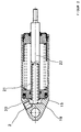
- Figure 1 shows a cylinder unit in the upper half of the picture and in the lower half of the picture a further development of the same.
- a piston (6) between two housing stops (3) and (9) longitudinally displaceable and by means of a sealing element (5) sealed.
- the housing stops (3) and (9) limit the displaceability of the piston.
- the possible piston stroke, the working area of the cylinder unit the distance between the housing stops is defined (3, 9) minus the distance between the housing stops (3, 9) measured piston length.
- the piston (6) is divided by means of the sealing element (5) the interior of the housing into a pressure chamber (2) and a spring chamber (8th).
- the end face facing the pressure chamber (2) the piston (6) is a pressure chamber (2) delimiting Piston surface (15).
- the Pressure chamber (2) from one of the piston surface (15) opposite Housing surface (19) and the spring chamber (8) bounded by an unspecified case back.
- the pressure chamber (2) and the piston surface (15) are through Supply of pressure medium via a housing connection (1) can be pressurized into the pressure chamber (2).
- the spring chamber (8) is provided via a in the case bottom Breathing opening (10) is ventilated and is therefore under ambient pressure, which is generally equal to atmospheric pressure is. To protect against the ingress of dirt and moisture is the breathing opening (10) with a provided unspecified filter.
- a spring (12) is arranged between the side of the piston facing away from the piston surface (15) (6) and the case bottom is caught.
- the cylinder unit also has a piston rod (11) on, one end of which protrudes into the pressure chamber (2). Starting from this end, the piston rod penetrates (11) first the piston (6), then the spring chamber (8) and the housing bottom that closes the spring chamber (8) and ends outside the housing (7).
- the piston rod (11) is displaceable in the piston (6) and in the housing base guided.
- the guidance of the piston rod (11) in Piston (6) is sealed by means of a sealing element (4), so that no pressure medium along this guide can escape from the pressure chamber (2).
- An unspecified Sealing element in the housing bottom serves for protection against the ingress of dirt and moisture into the Housing interior.
- the piston rod (11) At its end located in the pressure chamber (2) the piston rod (11) has a head (17). Whose End face facing piston (6) forms one of the piston surface (15) opposite stop (18). This Stop (18) is shown with an area the piston surface (15) engages the one piston side Stop (16) forms. Are both stops (16 and 18) engaged, they limit the movability the piston rod (11) opposite the piston (6) in the direction of action of the piston surface (15) Pressure.
- the pressure acting on the piston surface (15) is under pressure also on the cross section of the piston rod (11), the the sealing element (4) between the piston (6) and the piston rod (11) is included. Therefore the Press the stop (18) of the piston rod (11) and piston rod force prestressing the stop (16) of the piston (6). First of all, this supports the piston rod force the piston force generated by the pressure and causes that the piston rod (11) with the piston (6) shifts.
- the piston (6) drives the piston rod (11) only indirectly.
- the piston rod (11) When it is moved, the piston rod (11) is in the Position, a force on an object moved by it up to the size of the pressure exerted on them Piston rod force plus the frictional force of the sealing element (4) exercise. The object takes this power on, the common displacement of the piston rod ends (11) and piston (6).
- the behavior of the piston rod (11) with further displacement of the piston (6) depends on the force the object moved by it is able to absorb. The necessary for further displacement of the piston Increasing pressure also increases the piston rod force. Is the object moved by the piston rod (11) able, about because he's against a stop runs to fully absorb the increase in piston rod force, the piston rod (11) stops. Does the Object on the piston rod (11) against that of the piston rod force generated by the pressure plus this the frictional force of the sealing element (4) predominates Force, the piston rod (11) is also counter-rotating slidable to the piston (6). However, is the object unable to increase the piston rod force fully take up, the piston rod (11) to Reinstall their stop (18) on the piston side Stop (16) moved independently of the piston (6).
- the cylinder unit is the stops (16th and 18) of the piston (6) and the piston rod (11) biasing Force partially generated by a bias spring. This is between the piston (6) and the piston rod (11) caught. For this purpose it is on the inside part of the piston rod of the spring chamber (8) (11) a spring plate (13) attached. Between this spring plate (13) and one not specified Part of the piston (6) is the biasing spring (14) captured.
- the biasing spring (14) is designed as a compression spring.
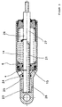
- the piston rod is in this embodiment (22) hollow over part of its length.
- the preload spring is in the resulting cavity (21) arranged.
- the trained again as a compression spring Preload spring (21) is between the end face of the cavity within the piston rod and that of Piston surface (15) opposite housing wall (19), that is between the piston rod and a housing wall, captured.
- Figure 3 shows in the upper half of the picture and in the lower Half of the picture different configurations of an embodiment for applications in which none pressure-related piston rod force required and / or is desired. Characteristic of both designs is that in the upper half of the picture with (26) and piston rod marked (27) in the lower half of the figure sealed with its end penetrating the piston (6) into a piston surface (15) opposite Housing part (23, 25) penetrates.
- This part of the case (23, 25) consists of one of the piston surfaces (15) opposite housing wall (25) and an adjoining Housing cavity (23).
- the seal serves a sealing element (24) in the housing wall (25).
- the seal element (24) included cross section of the piston rod (26 or 27) equal to that of the sealing element (4) between the piston (6) and the piston rod (26 or 27) included Cross-section. Therefore occurs in the illustrated embodiment no pressure-related piston rod force at all on. In this case, the pretension must only be applied by the bias spring.
- the Diameter of the piston rod (26, 27) in the area of Sealing element (24) can be reduced so that the Sealing element (24) enclosed cross section smaller than the cross section enclosed by the sealing element (4) the piston rod (26, 27) and a pressure-related Remaining piston rod force remains.
- the piston rod (26, 27) enters the housing cavity (23) one that uses an anti-intrusion Breath opening protected from dirt and moisture (28) is secured against pressure build-up. It is understood that the cavity (23) in the direction of displacement must be sufficiently dimensioned to achieve the end position of the piston (16) and piston rod (26, 27) guarantee.
- bias spring leans this embodiment in the upper half of the picture the solution according to the lower half of the figure 1 and in the lower half of the picture to the solution according to FIG. 2 on.
- the preload spring is in the lower half of the picture (21) between the face of the cavity in the Piston rod (27) and the bottom of the housing cavity (23) caught.
- this embodiment can even without receiving the piston rod (26, 27) Housing cavity (23) are formed.
- the piston rod (26, 27) would in this case go beyond that Sealing element (24) receiving housing wall (25) ends freely and be movable.
- cylinder unit As applications of the cylinder unit according to the invention are examples from the field of vehicle technology Devices for traction control or for Actuation of an exhaust throttle valve mentioned. In the interior the invention saves on traction slip control that mentioned in the above-mentioned WABCO publication separate compensating link.
- An exhaust throttle serves to reinforce the braking effect of the drive motor.
- the device for operating a such an exhaust throttle valve serves the cylinder unit Closing the exhaust throttle valve and limiting the Exhaust gas back pressure occurring upstream of the exhaust throttle valve.
Landscapes
- Engineering & Computer Science (AREA)
- Physics & Mathematics (AREA)
- Fluid Mechanics (AREA)
- Mechanical Engineering (AREA)
- General Engineering & Computer Science (AREA)
- Actuator (AREA)
- Transmission Devices (AREA)
- Vehicle Body Suspensions (AREA)
Description
- Figur 1
- zwei Ausgestaltungen einer Zylindereinheit,
- Figur 2
- eine andere Zylindereinheit,
- Figur 3
- zwei Ausgestaltungen einer weiteren Zylindereinheit.
Claims (6)
- Zylindereinheit mit einem in einem Gehäuse (7) angeordneten, eine druckbeaufschlagbare Kolbenfläche (15) aufweisenden Kolben (6) und einer Kolbenstange (11, 22), mit folgenden Merkmalen:a) die Kolbenstange (11, 22) ist gegenüber dem Kolben (6) verschiebbar;b) die Verschiebbarkeit der Kolbenstange (11, 22) ist in Wirkrichtung des die Kolbenfläche (15) beaufschlagenden Druckes durch Anschläge (16, 18) an dem Kolben (6) und an der Kolbenstange (11, 22) begrenzt;c) die Anschläge (16, 18) sind mit vorbestimmter Kraft gegeneinander vorgespannt;d) zwischen der Kolbenstange (11, 22) und dem Kolben (6) ist ein Dichtelement (4) angeordnet;
gekennzeichnet durch die folgenden Merkmale:e) im Gehäuse (7) ist eine Feder (12) angeordnet, die zwischen der der druckbeaufschlagbaren Kolbenfläche (15) abgewandten Seite des Kolbens (6) und einem Gehäuseboden gefangen ist;f) der Kolben (6), die Kolbenstange (11, 22) und das Dichtelement (4) sind so ausgebildet und so zueinander angeordnet, daß bei einer Druckbeaufschlagung der Kolbenfläche (15) und der Kolbenstange (11, 22,) die Kolbenstange (11, 22) auf einen von ihr bewegten Gegenstand eine Kraft bis zu der Größe der auf sie vom Druck ausgeübten Kolbenstangenkraft zuzüglich der Reibkraft des Dichtelementes (4) ausübt. - Zylindereinheit mit einem in einem Gehäuse (7) angeordneten, eine druckbeaufschlag bare Kolbenfläche (15) aufweisenden Kolben (6) und einer Kolbenstange (26, 27), mit folgenden Merkmalen:a) die Kolbenstange (26, 27) ist gegenüber dem Kolben (6) verschiebbar;b) die Verschiebbarkeit der Kolbenstange (26, 27) ist in Wirkrichtung des die Kolbenfläche (15) beaufschlagenden Druckes durch Anschläge (16, 18) an dem Kolben (6) und an der Kolbenstange (26, 27) begrenzt;c) die Anschläge (16, 18) sind mit vorbestimmter Kraft gegeneinander vorgespannt;d) zwischen der Kolbenstange (26, 27) und dem Kolben (6) ist ein Dichtelement (4) angeordnet;
gekennzeichnet durch die folgenden Merkmale:e) im Gehäuse (7) ist eine Feder (12) angeordnet, die zwischen der der druckbeaufschlagbaren Kolbenfläche (15) abgewandten Seite des Kolbens (6) und einem Gehäuseboden gefangen ist;f) die die Anschläge (16, 18) vorspannende Kraft wird wenigstens teilweise von einer als Vorspannfeder dienenden weiteren Feder (14, 21) erzeugt;g) die Kolbenstange (26, 27) durchdringt abgedichtet den Kolben (6) und der an ihr angeordnete Anschlag steht der wenigstens teilweise als kolbenstangenseitiger Anschlag dienenden Kolbenfläche (15) gegenüber, wobei die Kolbenstange (26, 27) mit ihrem den Kolben (6) durchdringenden Ende abgedichtet in einen der Kolbenfläche (15) gegenüberstehenden Gehäuseteil (23, 25) eindringt oder diesen durchdringt;h) die Kolbenstange (26, 27) ist so ausgebildet, daß ihr Dichtquerschnitt in dem Kolben (6) gleich oder größer ist als ihr Dichtquerschnitt im Gehäuseteil (25). - Zylindereinheit nach Anspruch 1, dadurch gekennzeichnet, daß die Kolbenstange (11; 22) den Kolben (6) abgedichtet durchdringt und der an ihr angeordnete Anschlag (18) der wenigstens teilweise als kolbenseitiger Anschlag (16) dienenden Kolbenfläche (15) gegenübersteht.
- Zylindereinheit nach einem der Ansprüche 1 oder 3,
dadurch gekennzeichnet, daß die die Anschläge (16, 18) vorspannende Kraft wenigstens teilweise von einer Vorspannfeder (14; 21) erzeugt wird. - Zylindereinheit nach wenigstens einem der Ansprüche, 2 oder 4
dadurch gekennzeichnet, daß die Vorspannfeder (14) zwischen dem Kolben (6) und der Kolbenstange (11) gefangen ist. - Zylindereinheit nach wenigstens einem der Ansprüche, 2 oder 4
dadurch gekennzeichnet, daß die Feder (21) zwischen der Kolbenstange (22; 27) und einer der Kolbenfläche (15) gegenüberstehenden Gehäusefläche (19) gefangen ist.
Applications Claiming Priority (2)
| Application Number | Priority Date | Filing Date | Title |
|---|---|---|---|
| DE4445145 | 1994-12-17 | ||
| DE4445145A DE4445145A1 (de) | 1994-12-17 | 1994-12-17 | Zylindereinheit |
Publications (3)
| Publication Number | Publication Date |
|---|---|
| EP0717200A2 EP0717200A2 (de) | 1996-06-19 |
| EP0717200A3 EP0717200A3 (de) | 1998-07-08 |
| EP0717200B1 true EP0717200B1 (de) | 2002-11-20 |
Family
ID=6536168
Family Applications (1)
| Application Number | Title | Priority Date | Filing Date |
|---|---|---|---|
| EP95116659A Expired - Lifetime EP0717200B1 (de) | 1994-12-17 | 1995-10-23 | Zylindereinheit |
Country Status (2)
| Country | Link |
|---|---|
| EP (1) | EP0717200B1 (de) |
| DE (2) | DE4445145A1 (de) |
Families Citing this family (1)
| Publication number | Priority date | Publication date | Assignee | Title |
|---|---|---|---|---|
| AU2018222981B2 (en) * | 2017-09-01 | 2024-03-14 | Enerpac Tool Group Corp. | Hybrid spring for a hydraulic cylinder |
Family Cites Families (7)
| Publication number | Priority date | Publication date | Assignee | Title |
|---|---|---|---|---|
| DE2128982A1 (de) * | 1971-06-11 | 1973-01-04 | Demag Ag | Hydraulisch oder pneumatisch beaufschlagter arbeitszylinder |
| DE2143712A1 (de) * | 1971-09-01 | 1973-03-08 | Westinghouse Bremsen Apparate | Druckmittelbetaetigbarer arbeitszylinder mit endstellungsarretierung |
| DE3125127A1 (de) * | 1981-06-26 | 1984-08-30 | Wabco Fahrzeugbremsen Gmbh, 3000 Hannover | Arbeitszylinder |
| FR2538468A1 (fr) * | 1982-12-22 | 1984-06-29 | Petroles Cie Francaise | Verin-amortisseur hydraulique notamment pour equipement sous-marin |
| GB2141176B (en) * | 1983-05-31 | 1986-11-26 | Bendix Ltd | Spring force applying tensional force actuators |
| DE3608791A1 (de) * | 1986-03-15 | 1987-09-17 | Teves Gmbh Alfred | Vorrichtung zur steuerung der antriebsleistung eines fahrzeugmotors fuer kraftfahrzeuge mit vortriebsregelung |
| DE3842348A1 (de) * | 1988-06-16 | 1989-12-21 | Wabco Westinghouse Fahrzeug | Antriebsschlupfregel- und fahrgeschwindigkeitsbegrenzungs-einrichtung |
-
1994
- 1994-12-17 DE DE4445145A patent/DE4445145A1/de not_active Withdrawn
-
1995
- 1995-10-23 EP EP95116659A patent/EP0717200B1/de not_active Expired - Lifetime
- 1995-10-23 DE DE59510465T patent/DE59510465D1/de not_active Expired - Fee Related
Also Published As
| Publication number | Publication date |
|---|---|
| DE59510465D1 (de) | 2003-01-02 |
| EP0717200A3 (de) | 1998-07-08 |
| DE4445145A1 (de) | 1996-06-20 |
| EP0717200A2 (de) | 1996-06-19 |
Similar Documents
| Publication | Publication Date | Title |
|---|---|---|
| DE69315194T2 (de) | Deckel mit volumenausgleichsvorrichtung fuer unter druck arbeitende hydraulischezylinder | |
| DE2918914A1 (de) | Bremskraftverstaerker | |
| DE2908516A1 (de) | Bremskraftverstaerker fuer ein kraftfahrzeug | |
| DE2904805A1 (de) | Druckluftgetriebener arbeitszylinder | |
| DE2617726A1 (de) | Modulator-baugruppe fuer hydraulische fahrzeug-bremsanlagen | |
| EP0025558A1 (de) | Entlüftungsvorrichtung für einen kombinierten Betriebsbrems- und Federspeicherbremszylinder | |
| DE10332001B3 (de) | Schockdämpfungselement | |
| DE2527091A1 (de) | Vorrichtung zur anpressung eines bandes gegen einen das band antreibenden oder bremsenden zylinder | |
| DE4104070A1 (de) | Bremszylinderdichtung mit ausnehmung | |
| EP0388586B2 (de) | Druckmittelbetätigbarer Arbeitszylinder | |
| EP0717200A2 (de) | Zylindereinheit | |
| EP0881134A2 (de) | Kraftspeicher | |
| DE2616973A1 (de) | Beidseitig wirkender pneumatischer arbeitszylinder mit stufenloser arretierung | |
| DE3113708A1 (de) | Pneumatischer kraftverstaerker, insbesondere fuer hydraulische kraftfahrzeug-bremsanlagen | |
| DE1032629B (de) | Elastischer Dichtungsring fuer zueinander bewegliche Teile | |
| EP0775619B1 (de) | Arbeitszylinder | |
| DE3707092A1 (de) | Verzoegerungsregler | |
| DE10046130B4 (de) | Elektromotorische Bremsbetätigungsvorrichtung für eine ein Bremsgestänge sowie Bremsbacken aufweisende Bremsmechanik, insbesondere für Schienenfahrzeuge | |
| DE102021119438A1 (de) | Pneumatisches Bremspedalmodul | |
| EP0602417B1 (de) | Kolbenstangenloser Arbeitszylinder | |
| DE4020904A1 (de) | Unterdruck-bremskraftverstaerker | |
| DE10046976A1 (de) | Druckbegrenzer für Pneumatikventile | |
| DE2337323A1 (de) | Bremskraftverstaerker | |
| DE2645471C2 (de) | Kraftverstärker für Hydraulikanlagen, insbesondere Bremsanlagen | |
| DE3037218C2 (de) | Hydraulisches Verstärkerventil, insbesondere für eine hydraulische Kraftfahrzeug-Bremsanlage |
Legal Events
| Date | Code | Title | Description |
|---|---|---|---|
| PUAI | Public reference made under article 153(3) epc to a published international application that has entered the european phase |
Free format text: ORIGINAL CODE: 0009012 |
|
| AK | Designated contracting states |
Kind code of ref document: A2 Designated state(s): DE FR GB IT SE |
|
| PUAL | Search report despatched |
Free format text: ORIGINAL CODE: 0009013 |
|
| AK | Designated contracting states |
Kind code of ref document: A3 Designated state(s): DE FR GB IT SE |
|
| RHK1 | Main classification (correction) |
Ipc: F15B 15/14 |
|
| RTI1 | Title (correction) | ||
| 17P | Request for examination filed |
Effective date: 19980615 |
|
| 17Q | First examination report despatched |
Effective date: 19991217 |
|
| RAP1 | Party data changed (applicant data changed or rights of an application transferred) |
Owner name: WABCO GMBH & CO. OHG |
|
| GRAG | Despatch of communication of intention to grant |
Free format text: ORIGINAL CODE: EPIDOS AGRA |
|
| GRAG | Despatch of communication of intention to grant |
Free format text: ORIGINAL CODE: EPIDOS AGRA |
|
| GRAH | Despatch of communication of intention to grant a patent |
Free format text: ORIGINAL CODE: EPIDOS IGRA |
|
| GRAH | Despatch of communication of intention to grant a patent |
Free format text: ORIGINAL CODE: EPIDOS IGRA |
|
| GRAA | (expected) grant |
Free format text: ORIGINAL CODE: 0009210 |
|
| AK | Designated contracting states |
Kind code of ref document: B1 Designated state(s): DE FR GB IT SE |
|
| REG | Reference to a national code |
Ref country code: GB Ref legal event code: FG4D Free format text: NOT ENGLISH |
|
| REF | Corresponds to: |
Ref document number: 59510465 Country of ref document: DE Date of ref document: 20030102 |
|
| GBT | Gb: translation of ep patent filed (gb section 77(6)(a)/1977) |
Effective date: 20030327 |
|
| ET | Fr: translation filed | ||
| PLBE | No opposition filed within time limit |
Free format text: ORIGINAL CODE: 0009261 |
|
| STAA | Information on the status of an ep patent application or granted ep patent |
Free format text: STATUS: NO OPPOSITION FILED WITHIN TIME LIMIT |
|
| 26N | No opposition filed |
Effective date: 20030821 |
|
| PGFP | Annual fee paid to national office [announced via postgrant information from national office to epo] |
Ref country code: DE Payment date: 20081031 Year of fee payment: 14 |
|
| PGFP | Annual fee paid to national office [announced via postgrant information from national office to epo] |
Ref country code: SE Payment date: 20081015 Year of fee payment: 14 Ref country code: IT Payment date: 20081023 Year of fee payment: 14 |
|
| PGFP | Annual fee paid to national office [announced via postgrant information from national office to epo] |
Ref country code: FR Payment date: 20081027 Year of fee payment: 14 |
|
| PGFP | Annual fee paid to national office [announced via postgrant information from national office to epo] |
Ref country code: GB Payment date: 20081022 Year of fee payment: 14 |
|
| EUG | Se: european patent has lapsed | ||
| REG | Reference to a national code |
Ref country code: FR Ref legal event code: ST Effective date: 20100630 |
|
| PG25 | Lapsed in a contracting state [announced via postgrant information from national office to epo] |
Ref country code: FR Free format text: LAPSE BECAUSE OF NON-PAYMENT OF DUE FEES Effective date: 20091102 Ref country code: DE Free format text: LAPSE BECAUSE OF NON-PAYMENT OF DUE FEES Effective date: 20100501 |
|
| PG25 | Lapsed in a contracting state [announced via postgrant information from national office to epo] |
Ref country code: GB Free format text: LAPSE BECAUSE OF NON-PAYMENT OF DUE FEES Effective date: 20091023 |
|
| PG25 | Lapsed in a contracting state [announced via postgrant information from national office to epo] |
Ref country code: IT Free format text: LAPSE BECAUSE OF NON-PAYMENT OF DUE FEES Effective date: 20091023 |
|
| PG25 | Lapsed in a contracting state [announced via postgrant information from national office to epo] |
Ref country code: SE Free format text: LAPSE BECAUSE OF NON-PAYMENT OF DUE FEES Effective date: 20091024 |