EP0715941A2 - Schliesseinheit für eine Spritzgiessmaschine - Google Patents
Schliesseinheit für eine Spritzgiessmaschine Download PDFInfo
- Publication number
- EP0715941A2 EP0715941A2 EP95115194A EP95115194A EP0715941A2 EP 0715941 A2 EP0715941 A2 EP 0715941A2 EP 95115194 A EP95115194 A EP 95115194A EP 95115194 A EP95115194 A EP 95115194A EP 0715941 A2 EP0715941 A2 EP 0715941A2
- Authority
- EP
- European Patent Office
- Prior art keywords
- unit according
- rod
- axially movable
- closing unit
- axially
- Prior art date
- Legal status (The legal status is an assumption and is not a legal conclusion. Google has not performed a legal analysis and makes no representation as to the accuracy of the status listed.)
- Granted
Links
Images

Classifications
-
- B—PERFORMING OPERATIONS; TRANSPORTING
- B29—WORKING OF PLASTICS; WORKING OF SUBSTANCES IN A PLASTIC STATE IN GENERAL
- B29C—SHAPING OR JOINING OF PLASTICS; SHAPING OF MATERIAL IN A PLASTIC STATE, NOT OTHERWISE PROVIDED FOR; AFTER-TREATMENT OF THE SHAPED PRODUCTS, e.g. REPAIRING
- B29C45/00—Injection moulding, i.e. forcing the required volume of moulding material through a nozzle into a closed mould; Apparatus therefor
- B29C45/17—Component parts, details or accessories; Auxiliary operations
- B29C45/64—Mould opening, closing or clamping devices
- B29C45/67—Mould opening, closing or clamping devices hydraulic
-
- B—PERFORMING OPERATIONS; TRANSPORTING
- B29—WORKING OF PLASTICS; WORKING OF SUBSTANCES IN A PLASTIC STATE IN GENERAL
- B29C—SHAPING OR JOINING OF PLASTICS; SHAPING OF MATERIAL IN A PLASTIC STATE, NOT OTHERWISE PROVIDED FOR; AFTER-TREATMENT OF THE SHAPED PRODUCTS, e.g. REPAIRING
- B29C45/00—Injection moulding, i.e. forcing the required volume of moulding material through a nozzle into a closed mould; Apparatus therefor
- B29C45/03—Injection moulding apparatus
- B29C45/04—Injection moulding apparatus using movable moulds or mould halves
- B29C45/06—Injection moulding apparatus using movable moulds or mould halves mounted on a turntable, i.e. on a rotating support having a rotating axis parallel to the mould opening, closing or clamping direction
- B29C45/062—Injection moulding apparatus using movable moulds or mould halves mounted on a turntable, i.e. on a rotating support having a rotating axis parallel to the mould opening, closing or clamping direction carrying mould halves co-operating with fixed mould halves
-
- B—PERFORMING OPERATIONS; TRANSPORTING
- B29—WORKING OF PLASTICS; WORKING OF SUBSTANCES IN A PLASTIC STATE IN GENERAL
- B29C—SHAPING OR JOINING OF PLASTICS; SHAPING OF MATERIAL IN A PLASTIC STATE, NOT OTHERWISE PROVIDED FOR; AFTER-TREATMENT OF THE SHAPED PRODUCTS, e.g. REPAIRING
- B29C45/00—Injection moulding, i.e. forcing the required volume of moulding material through a nozzle into a closed mould; Apparatus therefor
- B29C45/17—Component parts, details or accessories; Auxiliary operations
- B29C45/1761—Means for guiding movable mould supports or injection units on the machine base or frame; Machine bases or frames
-
- B—PERFORMING OPERATIONS; TRANSPORTING
- B29—WORKING OF PLASTICS; WORKING OF SUBSTANCES IN A PLASTIC STATE IN GENERAL
- B29C—SHAPING OR JOINING OF PLASTICS; SHAPING OF MATERIAL IN A PLASTIC STATE, NOT OTHERWISE PROVIDED FOR; AFTER-TREATMENT OF THE SHAPED PRODUCTS, e.g. REPAIRING
- B29C45/00—Injection moulding, i.e. forcing the required volume of moulding material through a nozzle into a closed mould; Apparatus therefor
- B29C45/16—Making multilayered or multicoloured articles
- B29C45/1615—The materials being injected at different moulding stations
- B29C45/162—The materials being injected at different moulding stations using means, e.g. mould parts, for transferring an injected part between moulding stations
-
- B—PERFORMING OPERATIONS; TRANSPORTING
- B29—WORKING OF PLASTICS; WORKING OF SUBSTANCES IN A PLASTIC STATE IN GENERAL
- B29L—INDEXING SCHEME ASSOCIATED WITH SUBCLASS B29C, RELATING TO PARTICULAR ARTICLES
- B29L2017/00—Carriers for sound or information
- B29L2017/001—Carriers of records containing fine grooves or impressions, e.g. disc records for needle playback, cylinder records
- B29L2017/003—Records or discs
- B29L2017/005—CD''s, DVD''s
Definitions
- the invention relates to a clamping unit for an injection molding machine according to the preamble of patent claim 1.
- German patent DE 37 18 106 a clamping unit for injection molding machines is known, the displaceable mold mounting plate being guided in a linear roller guide on the machine bed and being pulled against the fixed mold mounting plate by means of an axial tensile force applied via two symmetrically arranged ball screws.
- the disadvantages of tool clamping plates guided on spars, such as the imprecise parallel guidance of the movable plate, are only partially eliminated by such an arrangement.
- the area available for clamping the tools is limited by the lateral arrangement of the ball spindles, similar to the version with bars, and makes access to the tools to be clamped more difficult.
- the invention is therefore based on the object of creating a clamping unit with precise parallel guidance, the tool clamping plates of which have the largest possible area for clamping the tools with free access from several sides.
- the clamping unit according to the invention enables both double or multiple production with the same tools, for example for CD production, and production with different tools, for example for producing a housing and the associated cover or also differently colored parts or different masses. If only one tool is to be clamped, a pair of support blocks or spacers can be used instead of a second tool to compensate.
- the movable platen is rotatably arranged around the rod and several tools can be clamped in the manner of a drum turret.
- several CDs can be produced in one and the same process.
- the clamping unit with the tool clamping plates and the pull rod can be arranged both horizontally and vertically.
- the platen plates are advantageously supported on a machine bed so that they can slide horizontally and are supported in ball tracks with an integrated path measuring system.
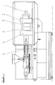
- An injection molding machine 1 of the type shown in FIGS. 1 and 2 consists essentially of a machine bed 2, two injection molding units 3 and 4 and a closing unit 5, which are arranged symmetrically to the central longitudinal axis A of the injection molding machine 1.
- the clamping unit 5 consists of an axially fixed 6 and an axially movable tool mounting plate 8, which is slidably supported on a slide rail 7, with tools 9, 10 consisting of tool halves clamped thereon and ejectors 11, 12 for the injection molded parts.
- the movable platen 8 is fixedly connected to a rod 13 which, as a piston rod, is part of a piston-cylinder unit 14 with a locking cylinder and is freely guided through the fixed platen 6.
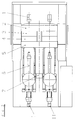
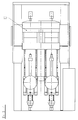
- a turntable 16 is arranged on an axially movable platen 15.
- two tool halves 17 and 18 are arranged symmetrically to the central longitudinal axis A and to the center of gravity S of the rotary table 16 or the axially movable platen 15 on the turntable 16 rotatable about the central longitudinal axis A.
- a lower, axially fixed platen 19 is designed as a rotary table with a rotary table stand 20 and a drive 21.
- a driving cylinder 22 with a pressure intensifier 23 By means of a driving cylinder 22 with a pressure intensifier 23, an upper, axially movable tool mounting plate 24 pulled down onto the rotary table 19 by means of a rod 25 attached to it and thus the tool halves 26 and 27 as well as 28 and 29 brought together for the injection molding process.
- One or more injection units 30 are provided for the spraying process.
- Pressure distributors 31 and a sensor 32, above which rotary distributors 33, 34, 35 are provided for the supply of compressed air, water and electricity, are provided on the axially movable platen 24.
Landscapes
- Engineering & Computer Science (AREA)
- Manufacturing & Machinery (AREA)
- Mechanical Engineering (AREA)
- Injection Moulding Of Plastics Or The Like (AREA)
- Moulds For Moulding Plastics Or The Like (AREA)
- Automatic Tool Replacement In Machine Tools (AREA)
Abstract
Description
- Die Erfindung bezieht sich auf eine Schließeinheit für eine Spritzgießmaschine gemäß dem Oberbegriff des Patentanspruchs 1.
- Nach der deutschen Patentschrift DE 37 18 106 ist eine Schließeinheit für Spritzgießmaschinen bekannt, wobei die verschiebbare Werkzeugaufspannplatte in einer Linearwälzführung auf dem Maschinenbett geführt ist und mittels einer über zwei symmetrisch angeordnete Kugelspindeln aufgebrachten Axialzugkraft gegen die feste Werkzeugaufspannplatte gezogen wird. Die Nachteile bei an Holmen geführten Werkzeugaufspannplatten wie z.B die nicht präzise Parallelführung der beweglichen Platte werden durch eine derartige Anordnung aber nur teilweise aufgehoben.
- Dagegen ist die zum Aufspannen der Werkzeuge zur Verfügung stehende Fläche ähnlich wie bei der Ausführung mit Holmen durch die seitliche Anordnung der Kugelspindeln begrenzt und erschwert den Zugang zu den aufzuspannenden Werkzeugen.
- Der Erfindung liegt daher die Aufgabe zugrunde, eine Schließeinheit mit präziser Parallelführung zu schaffen, deren Werkzeugaufspannplatten eine möglichst große Fläche zum Aufspannen der Werkzeuge bei freiem Zugang von mehreren Seiten aufweisen.
- Diese Aufgabe wird gemäß den Merkmalen des Patentanspruchs 1 gelöst.
- Die erfindungsgemäße Schließeinheit ermöglicht sowohl eine Doppel-oder Mehrfachproduktion mit gleichen Werkzeugen, wie z.B. zur CD-Herstellung als auch eine Produktion mit verschiedenen Werkzeugen, z.B. zur Herstellung eines Gehäuses und des zugehörigen Deckels oder auch verschiedenfarbiger Teile bzw. unterschiedlicher Massen. Falls nur ein Werkzeug aufgespannt werden soll, können zum Ausgleich anstelle eines zweiten Werkzeugs auch ein Paar Stützblöcke bzw. Abstandshalter verwendet werden.
- In vorteilhafter Ausbildung der Erfindung ist die bewegliche Werkzeugaufspannplatte um die Stange drehbar angeordnet und mehrere Werkzeuge nach Art eines Trommelrevolvers aufspannbar. Mit einer derartigen Anordnung können z.B. mehrere CD's in ein und demselben Vorgang hergestellt werden.
- Die Schließeinheit mit den Werkzeugaufspannplatten und der Zugstange kann sowohl horizontal als auch vertikal angeordnet sein.
- Bei horizontal er Anordnung sind die Werkzeugaufspannplatten vorteilhaft auf einem Maschinenbett horizontal gleitbar abgestützt und in Kugelbahnen mit einem integrierten Wegemeßsystem gelagert.
- Bei vertikaler Anordnung ergibt sich vorteilhaft allseitig ein freier Zugang zur Aufspannfläche sowie eine besonders kompakte Bauweise der Maschine.
- An den Werkzeugaufspannplatten vorteilhaft angeordnete Sensoren stellen sicher, daß alle Werkzeughälften eingebaut sind und beim Schließvorgang keine Beschädigungen entstehen können.
- In der Zeichnung sind Ausführungsbeispiele der Erfindung dargestellt. Es zeigen:
- Fig. 1
- Eine Spritzgießmaschine mit zwei Spritzgießeinheiten in einer Seitenansicht,
- Fig. 2
- eine Spritzgießmaschine gemäß Fig. 1 in der Draufsicht,
- Fig. 3
- eine Spritzgießmaschine entsprechend Fig. 1, zusätzlich mit integriertem Drehtisch,
- Fig. 4
- eine Draufsicht gemäß Fig. 3,
- Fig. 5
- den Drehtisch gemäß Fig. 3 und 4 in einer Vorderansicht,
- Fig. 6
- eine vertikal angeordnete Spritzgießmaschine.
- Eine Spritzgießmaschine 1 der gemäß Fig. 1 und 2 dargestellten Art besteht im wesentlichen aus einem Maschinenbett 2, zwei Spritzgießeinheiten 3 und 4 sowie einer Schließeinheit 5, die symmetrisch zur Mittellängsachse A der Spritzgießmaschine 1 angeordnet sind. Die Schließeinheit 5 besteht aus einer axial festen 6 und einer auf einer Gleitschiene 7 gleitbar abgestützten, axial beweglichen Werkzeugaufspannplatte 8 mit darauf aufgespannten aus Werkzeughälften bestehenden Werkzeugen 9, 10 sowie Auswerfern 11, 12 für die Spritzgießteile. Die bewegliche Werkzeugaufspannplatte 8 ist mit einer Stange 13 fest verbunden, die als Kolbenstange Bestandteil einer Kolben-Zylindereinheit 14 mit einem Schließzylinder und durch die feste Werkzeugaufspannplatte 6 frei hindurchgeführt ist.
- Nach Fig. 3 und 4 ist an einer axial beweglichen Werkzeugaufspannplatte 15 ein Drehtisch 16 angeordnet.
- Gemäß Fig. 5 sind auf dem um die Mittellängsachse A drehbaren Drehtisch 16 zwei Werkzeughälften 17 und 18 symmetrisch zur Mittellängsachse A und zum Schwerpunkt S des Drehtisches 16 bzw. der axial beweglichen Aufspannplatte 15 angeordnet.
- Bei der vertikalen Anordnung ist eine untere, axial feste Werkzeugaufspannplatte 19 als Rundtisch mit einem Rundtischständer 20 und einem Antrieb 21 ausgebildet. Mittels eines Fahrzylinders 22 mit einem Druckübersetzer 23 wird eine obere, axial bewegliche Werkzeugaufspannplatte 24 mittels einer daran befestigten Stange 25 auf den Rundtisch 19 herabgezogen und damit die Werkzeughälften 26 und 27 sowie 28 und 29 für den Spritzvorgang zusammengeführt. Für den Spritzvorgang sind ein bzw. mehrere Spritzaggregate 30 vorgesehen. An der axial beweglichen Werkzeugaufspannplatte 24 sind Druckverteiler 31 sowie ein Sensor 32, oberhalb davon Drehverteiler 33, 34, 35 für die Zuführung von Druckluft, Wasser und Strom vorgesehen.
Claims (9)
- Schließeinheit für eine holmlose Spritzgießmaschine mit einer axial festen und einer damit korrespondierenden axial beweglichen Werkzeugaufspannplatte zum Aufspannen von Formwerkzeugen mit einem Antrieb zum Bewegen der axial beweglichen gegenüber der axial festen Werkzeugaufspannplatte mittels Axialzugkraft, dadurch gekennzeichnet, daß die axial bewegliche Werkzeugaufspannplatte (8) mittels einer daran innerhalb des Aufspannbereichs befestigten und beim Schließvorgang auf Zug beanspruchten Stange (13) gegenüber der axial festen Werkzeugaufspannplatte (6) bewegbar ist.
- Schließeinheit nach Anspruch 1, dadurch gekennzeichnet, daß die Stange (13) als Kolbenstange einer Kolben-Zylindereinheit ausgebildet ist.
- Schließeinheit nach den Ansprüchen 1 und 2, dadurch gekennzeichnet, daß die Stange (13) in der Mittellängsachse (A) der Spritzgießmaschine und im Schwerpunkt (S) von zwei oder mehreren aufgespannten Formwerkzeugen (9, 10) angeordnet ist.
- Schließeinheit nach den Ansprüchen 1 bis 3 oder einem derselben, dadurch gekennzeichnet, daß die axial bewegliche Werkzeugaufspannplatte (8) mit einem um die Mittellängsachse (A) drehbaren Rundtisch (16) zum Aufspannen von mehreren Werkzeugen nach Art eines Trommelrevolvers versehen ist.
- Schließeinheit nach den Ansprüchen 1 bis 4 oder einem derselben, dadurch gekennzeichnet, daß die axial bewegliche Werkzeugaufspannplatte (8) auf einem Maschinenbett (2) horizontal gleitbar über eine Gleitschiene (7) abgestützt ist.
- Schließeinheit nach Anspruch 5, dadurch gekennzeichnet, daß die axial bewegliche Werkzeugaufspannplatte (8) auf dem Maschinenbett (7) in Kugelbahnen mit einem integrierten Wegemeßsystem gelagert ist.
- Schließeinheit nach den Ansprüchen 1 bis 4 oder einem derselben, dadurch gekennzeichnet, daß die Werkzeugaufspannplatten (19,24) und die Stange (25) vertikal angeordnet sind.
- Schließeinheit nach Anspruch 7, dadurch gekennzeichnet, daß die axial feste Werkzeugaufspannplatte (19) als Rundtisch unterhalb der axial beweglichen Werkzeugaufspannplatte (24) angeordnet ist.
- Schließeinheit nach den Ansprüchen 1 bis 8 oder einem derselben, dadurch gekennzeichnet, daß an der beweglichen Werkzeugaufspannplatte und/oder der festen Werkzeugaufspannplatte jeweils ein oder mehrere Sensoren (32) angeordnet sind.
Applications Claiming Priority (2)
| Application Number | Priority Date | Filing Date | Title |
|---|---|---|---|
| DE4443689A DE4443689A1 (de) | 1994-12-08 | 1994-12-08 | Schließeinheit für eine Spritzgießmaschine |
| DE4443689 | 1994-12-08 |
Publications (3)
| Publication Number | Publication Date |
|---|---|
| EP0715941A2 true EP0715941A2 (de) | 1996-06-12 |
| EP0715941A3 EP0715941A3 (de) | 1997-01-08 |
| EP0715941B1 EP0715941B1 (de) | 2000-04-26 |
Family
ID=6535261
Family Applications (1)
| Application Number | Title | Priority Date | Filing Date |
|---|---|---|---|
| EP95115194A Expired - Lifetime EP0715941B1 (de) | 1994-12-08 | 1995-09-27 | Schliesseinheit für eine Spritzgiessmaschine |
Country Status (6)
| Country | Link |
|---|---|
| US (1) | US5736169A (de) |
| EP (1) | EP0715941B1 (de) |
| JP (1) | JPH08224763A (de) |
| AT (1) | ATE192068T1 (de) |
| DE (2) | DE4443689A1 (de) |
| ES (1) | ES2145195T3 (de) |
Families Citing this family (8)
| Publication number | Priority date | Publication date | Assignee | Title |
|---|---|---|---|---|
| US6152721A (en) | 1998-03-30 | 2000-11-28 | Husky Injection Molding Systems Ltd. | Shooting pot actuator for an injection molding machine |
| JP3759480B2 (ja) * | 2001-10-05 | 2006-03-22 | 東洋機械金属株式会社 | 射出成形機 |
| US6510720B1 (en) * | 2001-10-18 | 2003-01-28 | Hartwick Professionals, Inc. | Hydraulic pressure forming using a self aligning and activating die system |
| JP3998656B2 (ja) | 2004-03-30 | 2007-10-31 | 太陽誘電株式会社 | 射出成形装置及び射出成形方法 |
| DE102013216008A1 (de) * | 2013-08-13 | 2015-02-19 | Otto Männer Innovation GmbH | Spritzgießmaschine für mehrere Spritzgießvorgänge |
| CN111231211A (zh) * | 2020-01-19 | 2020-06-05 | 东莞市周翔塑胶科技有限公司 | 一种双色注射设备 |
| JP2024539419A (ja) * | 2021-11-22 | 2024-10-28 | キヤノンバージニア, インコーポレイテッド | 射出成形システム |
| JP2023125419A (ja) * | 2022-02-28 | 2023-09-07 | トヨタ自動車株式会社 | 金型装置 |
Citations (1)
| Publication number | Priority date | Publication date | Assignee | Title |
|---|---|---|---|---|
| DE3718106A1 (de) | 1987-05-27 | 1988-12-15 | Mannesmann Ag | Praezisionsschliesseinheit fuer eine spritzgiessmaschine |
Family Cites Families (18)
| Publication number | Priority date | Publication date | Assignee | Title |
|---|---|---|---|---|
| DE1109356B (de) * | 1959-08-27 | 1961-06-22 | Heinz Maiberger | Spritzgussmaschine fuer thermoplastische Kunststoffe mit einer hydraulischen Formschliess- und Haltevorrichtung |
| DE1576162A1 (de) * | 1965-05-04 | 1970-06-18 | Boy Kg Dr | Hydraulische Antriebsvorrichtung fuer Werkzeuge od.dgl.,insbesondere fuer die beweglichen Formteile von Kunststoffspritzmaschinen |
| DE1957052A1 (de) * | 1969-11-13 | 1971-05-27 | Walter Theobald | Spannungsfreies Maschinengestell fuer Scheren,Pressen aller Art,Schmiedemaschinen u.dgl. |
| JPS5658841A (en) * | 1979-10-18 | 1981-05-22 | Sekisui Chem Co Ltd | Rotary type molding machine |
| JPH0237854B2 (ja) * | 1983-02-22 | 1990-08-28 | Yamashiro Seiki Seisakusho Kk | Shashutsuseikeiki |
| JPS60247522A (ja) * | 1984-05-22 | 1985-12-07 | Toshiba Mach Co Ltd | 射出成形機等の移動プレ−ト停止位置制御方法 |
| JPS6129515A (ja) * | 1985-06-24 | 1986-02-10 | Katashi Aoki | 回転式射出成形機 |
| JPS62121023A (ja) * | 1985-11-22 | 1987-06-02 | Niigata Eng Co Ltd | 射出成形機 |
| US5007822A (en) * | 1987-08-28 | 1991-04-16 | Sumitomo Heavy Industries, Ltd. | Injection molding machine |
| JPH02305615A (ja) * | 1989-05-22 | 1990-12-19 | Sekisui Chem Co Ltd | 射出成形におけるゲートシール時間測定方法 |
| CH680576A5 (de) * | 1990-05-31 | 1992-09-30 | Kistler Instrumente Ag | |
| TW205018B (de) * | 1990-11-30 | 1993-05-01 | Toshiba Machine Co Ltd | |
| JPH06352B2 (ja) * | 1990-11-30 | 1994-01-05 | 日精樹脂工業株式会社 | 回転式射出成形機 |
| US5145353A (en) * | 1991-06-10 | 1992-09-08 | The Dow Chemical Company | Dual action molding press |
| AT398291B (de) * | 1992-03-24 | 1994-11-25 | Engel Gmbh Maschbau | Spritzgiessmaschine |
| DE9320508U1 (de) * | 1992-08-18 | 1994-08-25 | Engel Maschinenbau Ges.M.B.H., Schwertberg | Spritzgießmaschine |
| WO1994017977A1 (de) * | 1993-02-01 | 1994-08-18 | Bruno Svoboda | Spritzgiessmaschine |
| GB2307176A (en) * | 1995-11-15 | 1997-05-21 | Todd Selwyn Everest | Anti-inflammatory clathrating agents for topical use |
-
1994
- 1994-12-08 DE DE4443689A patent/DE4443689A1/de not_active Withdrawn
-
1995
- 1995-09-27 DE DE59508225T patent/DE59508225D1/de not_active Expired - Fee Related
- 1995-09-27 EP EP95115194A patent/EP0715941B1/de not_active Expired - Lifetime
- 1995-09-27 AT AT95115194T patent/ATE192068T1/de not_active IP Right Cessation
- 1995-09-27 ES ES95115194T patent/ES2145195T3/es not_active Expired - Lifetime
- 1995-12-04 US US08/566,784 patent/US5736169A/en not_active Expired - Fee Related
- 1995-12-05 JP JP7316831A patent/JPH08224763A/ja active Pending
Patent Citations (1)
| Publication number | Priority date | Publication date | Assignee | Title |
|---|---|---|---|---|
| DE3718106A1 (de) | 1987-05-27 | 1988-12-15 | Mannesmann Ag | Praezisionsschliesseinheit fuer eine spritzgiessmaschine |
Also Published As
| Publication number | Publication date |
|---|---|
| ATE192068T1 (de) | 2000-05-15 |
| EP0715941A3 (de) | 1997-01-08 |
| ES2145195T3 (es) | 2000-07-01 |
| DE4443689A1 (de) | 1996-06-13 |
| US5736169A (en) | 1998-04-07 |
| JPH08224763A (ja) | 1996-09-03 |
| DE59508225D1 (de) | 2000-05-31 |
| EP0715941B1 (de) | 2000-04-26 |
Similar Documents
| Publication | Publication Date | Title |
|---|---|---|
| EP1673208B1 (de) | Horizontal-spritzgiessmaschine mit dreheinrichtung | |
| EP1226916A1 (de) | Vorrichtung und Verfahren zur Herstellung von Objekten aus Kunststoff | |
| EP0311133A1 (de) | Spritzgiessmaschine | |
| EP0715941A2 (de) | Schliesseinheit für eine Spritzgiessmaschine | |
| EP0116132A1 (de) | Spritzpresse sowie Verfahren zum Herstellen von Spritzgussteilen | |
| EP0720525A1 (de) | Zweifach-schliesseinheit einer spritzgiessmaschine | |
| EP0583718B1 (de) | Kunststoff-Spritzgiessmaschine | |
| EP1802441B1 (de) | Schliesseinheit für eine spritzgiessmaschine mit etagenwerkzeug | |
| DE102009016783A1 (de) | Spritzeinheit einer Spritzgießmaschine | |
| EP0853537B1 (de) | Formschliesseinheit mit einer einrichtung zur entfernung von spritzteilen | |
| DE4223314A1 (de) | Einrichtung zum Schließen und Öffnen von Formen | |
| EP3378621B1 (de) | Etagenwerkzeug | |
| DE3529775C2 (de) | ||
| DE102008052950A1 (de) | Spritzgießmaschine | |
| DE3542878C2 (de) | ||
| EP0478903A1 (de) | Wechselkassettenvorrichtung für eine Rollenrotationsdruckmaschine | |
| DE4239775A1 (de) | Spritzgieß- oder Spritzprägemaschine | |
| EP1784295B1 (de) | Spritzgiessmaschine | |
| DE1938171C3 (de) | Vorrichtung zum Herstellen von Formteilen aus schaumbarem Kunststoff | |
| EP0549928A1 (de) | Gussmaschine, insbesondere Spritzgussmaschine | |
| EP0220496A2 (de) | Spritzgiessmaschine zum Herstellen von Kunststoffteilen im Spritzgiess- oder Reaktionsspritzgiessverfahren | |
| DE3712743A1 (de) | Vorrichtung zum reinigen der formen und/oder auswerfen der in den formen hergestellten gegenstaende fuer formpressen zur herstellung von gegenstaenden aus gummi oder gummiartigem kunststoff | |
| DE3715121C2 (de) | ||
| EP0593870A1 (de) | Formmaschine | |
| AT12173U1 (de) | Schliesseinheit für eine spritzgiessmaschine |
Legal Events
| Date | Code | Title | Description |
|---|---|---|---|
| PUAI | Public reference made under article 153(3) epc to a published international application that has entered the european phase |
Free format text: ORIGINAL CODE: 0009012 |
|
| AK | Designated contracting states |
Kind code of ref document: A2 Designated state(s): AT CH DE ES FR IT LI |
|
| PUAL | Search report despatched |
Free format text: ORIGINAL CODE: 0009013 |
|
| AK | Designated contracting states |
Kind code of ref document: A3 Designated state(s): AT CH DE ES FR IT LI |
|
| 17P | Request for examination filed |
Effective date: 19970624 |
|
| 17Q | First examination report despatched |
Effective date: 19990429 |
|
| GRAG | Despatch of communication of intention to grant |
Free format text: ORIGINAL CODE: EPIDOS AGRA |
|
| GRAG | Despatch of communication of intention to grant |
Free format text: ORIGINAL CODE: EPIDOS AGRA |
|
| GRAH | Despatch of communication of intention to grant a patent |
Free format text: ORIGINAL CODE: EPIDOS IGRA |
|
| RAP1 | Party data changed (applicant data changed or rights of an application transferred) |
Owner name: KRAUSS-MAFFEI KUNSTSTOFFTECHNIK GMBH |
|
| GRAH | Despatch of communication of intention to grant a patent |
Free format text: ORIGINAL CODE: EPIDOS IGRA |
|
| GRAA | (expected) grant |
Free format text: ORIGINAL CODE: 0009210 |
|
| AK | Designated contracting states |
Kind code of ref document: B1 Designated state(s): AT CH DE ES FR IT LI |
|
| REF | Corresponds to: |
Ref document number: 192068 Country of ref document: AT Date of ref document: 20000515 Kind code of ref document: T |
|
| REG | Reference to a national code |
Ref country code: CH Ref legal event code: EP |
|
| ET | Fr: translation filed | ||
| REF | Corresponds to: |
Ref document number: 59508225 Country of ref document: DE Date of ref document: 20000531 |
|
| ITF | It: translation for a ep patent filed | ||
| REG | Reference to a national code |
Ref country code: CH Ref legal event code: NV Representative=s name: KIRKER & CIE SA |
|
| REG | Reference to a national code |
Ref country code: ES Ref legal event code: FG2A Ref document number: 2145195 Country of ref document: ES Kind code of ref document: T3 |
|
| PLBE | No opposition filed within time limit |
Free format text: ORIGINAL CODE: 0009261 |
|
| STAA | Information on the status of an ep patent application or granted ep patent |
Free format text: STATUS: NO OPPOSITION FILED WITHIN TIME LIMIT |
|
| 26N | No opposition filed | ||
| PGFP | Annual fee paid to national office [announced via postgrant information from national office to epo] |
Ref country code: ES Payment date: 20030910 Year of fee payment: 9 |
|
| PGFP | Annual fee paid to national office [announced via postgrant information from national office to epo] |
Ref country code: DE Payment date: 20030911 Year of fee payment: 9 |
|
| PGFP | Annual fee paid to national office [announced via postgrant information from national office to epo] |
Ref country code: FR Payment date: 20030917 Year of fee payment: 9 |
|
| PGFP | Annual fee paid to national office [announced via postgrant information from national office to epo] |
Ref country code: AT Payment date: 20030919 Year of fee payment: 9 |
|
| PGFP | Annual fee paid to national office [announced via postgrant information from national office to epo] |
Ref country code: CH Payment date: 20030925 Year of fee payment: 9 |
|
| PG25 | Lapsed in a contracting state [announced via postgrant information from national office to epo] |
Ref country code: AT Free format text: LAPSE BECAUSE OF NON-PAYMENT OF DUE FEES Effective date: 20040927 |
|
| PG25 | Lapsed in a contracting state [announced via postgrant information from national office to epo] |
Ref country code: ES Free format text: LAPSE BECAUSE OF NON-PAYMENT OF DUE FEES Effective date: 20040928 |
|
| PG25 | Lapsed in a contracting state [announced via postgrant information from national office to epo] |
Ref country code: LI Free format text: LAPSE BECAUSE OF NON-PAYMENT OF DUE FEES Effective date: 20040930 Ref country code: CH Free format text: LAPSE BECAUSE OF NON-PAYMENT OF DUE FEES Effective date: 20040930 |
|
| PG25 | Lapsed in a contracting state [announced via postgrant information from national office to epo] |
Ref country code: DE Free format text: LAPSE BECAUSE OF NON-PAYMENT OF DUE FEES Effective date: 20050401 |
|
| REG | Reference to a national code |
Ref country code: CH Ref legal event code: PL |
|
| PG25 | Lapsed in a contracting state [announced via postgrant information from national office to epo] |
Ref country code: FR Free format text: LAPSE BECAUSE OF NON-PAYMENT OF DUE FEES Effective date: 20050531 |
|
| REG | Reference to a national code |
Ref country code: FR Ref legal event code: ST |
|
| PG25 | Lapsed in a contracting state [announced via postgrant information from national office to epo] |
Ref country code: IT Free format text: LAPSE BECAUSE OF NON-PAYMENT OF DUE FEES;WARNING: LAPSES OF ITALIAN PATENTS WITH EFFECTIVE DATE BEFORE 2007 MAY HAVE OCCURRED AT ANY TIME BEFORE 2007. THE CORRECT EFFECTIVE DATE MAY BE DIFFERENT FROM THE ONE RECORDED. Effective date: 20050927 |
|
| REG | Reference to a national code |
Ref country code: ES Ref legal event code: FD2A Effective date: 20040928 |