EP0853537B1 - Formschliesseinheit mit einer einrichtung zur entfernung von spritzteilen - Google Patents
Formschliesseinheit mit einer einrichtung zur entfernung von spritzteilen Download PDFInfo
- Publication number
- EP0853537B1 EP0853537B1 EP96943001A EP96943001A EP0853537B1 EP 0853537 B1 EP0853537 B1 EP 0853537B1 EP 96943001 A EP96943001 A EP 96943001A EP 96943001 A EP96943001 A EP 96943001A EP 0853537 B1 EP0853537 B1 EP 0853537B1
- Authority
- EP
- European Patent Office
- Prior art keywords
- mould
- arrangement
- closing unit
- drive unit
- actuating element
- Prior art date
- Legal status (The legal status is an assumption and is not a legal conclusion. Google has not performed a legal analysis and makes no representation as to the accuracy of the status listed.)
- Expired - Lifetime
Links
Images


Classifications
-
- B—PERFORMING OPERATIONS; TRANSPORTING
- B29—WORKING OF PLASTICS; WORKING OF SUBSTANCES IN A PLASTIC STATE IN GENERAL
- B29C—SHAPING OR JOINING OF PLASTICS; SHAPING OF MATERIAL IN A PLASTIC STATE, NOT OTHERWISE PROVIDED FOR; AFTER-TREATMENT OF THE SHAPED PRODUCTS, e.g. REPAIRING
- B29C45/00—Injection moulding, i.e. forcing the required volume of moulding material through a nozzle into a closed mould; Apparatus therefor
- B29C45/17—Component parts, details or accessories; Auxiliary operations
- B29C45/40—Removing or ejecting moulded articles
- B29C45/4005—Ejector constructions; Ejector operating mechanisms
-
- B—PERFORMING OPERATIONS; TRANSPORTING
- B29—WORKING OF PLASTICS; WORKING OF SUBSTANCES IN A PLASTIC STATE IN GENERAL
- B29C—SHAPING OR JOINING OF PLASTICS; SHAPING OF MATERIAL IN A PLASTIC STATE, NOT OTHERWISE PROVIDED FOR; AFTER-TREATMENT OF THE SHAPED PRODUCTS, e.g. REPAIRING
- B29C45/00—Injection moulding, i.e. forcing the required volume of moulding material through a nozzle into a closed mould; Apparatus therefor
- B29C45/17—Component parts, details or accessories; Auxiliary operations
- B29C45/26—Moulds
- B29C45/2618—Moulds having screw-threaded mould walls
- B29C45/262—Moulds having screw-threaded mould walls provided with unscrewing drive means
-
- B—PERFORMING OPERATIONS; TRANSPORTING
- B29—WORKING OF PLASTICS; WORKING OF SUBSTANCES IN A PLASTIC STATE IN GENERAL
- B29C—SHAPING OR JOINING OF PLASTICS; SHAPING OF MATERIAL IN A PLASTIC STATE, NOT OTHERWISE PROVIDED FOR; AFTER-TREATMENT OF THE SHAPED PRODUCTS, e.g. REPAIRING
- B29C45/00—Injection moulding, i.e. forcing the required volume of moulding material through a nozzle into a closed mould; Apparatus therefor
- B29C45/17—Component parts, details or accessories; Auxiliary operations
- B29C45/40—Removing or ejecting moulded articles
- B29C45/4005—Ejector constructions; Ejector operating mechanisms
- B29C2045/4036—Ejector constructions; Ejector operating mechanisms driven by a screw and nut mechanism
Definitions
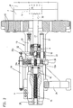
- the drive unit A for the spindle 15 is an electromechanical one Drive provided in the form of a space-saving hollow shaft motor.
- the entire device is designed so that at least the drive unit A, the support member and the actuator one self-contained and detachable from the mold clamping unit F. form a structural unit.
- the machine in the area of the tool M distributed various connections can be provided, which then Controlled on the control side via a corresponding interface can be.
- the structural unit has coupling means 18 through which the Spindle 15 can be coupled as an actuating element to the treatment element 17 is.
- This has the advantage that corresponding ejectors the tool can be replaced or that the treatment elements depending on their task, be it as an ejector, core puller or unscrewing mechanism can be replaced.
- the structural A path measuring device 19 e.g. in shape a linear potentiometer. Through the signals of this Travel measuring device can regulate or control the drive unit A. become.
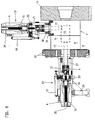
- the drive unit A is at a distance from Tool M.
- the drive unit here a hollow shaft motor for reasons of space, is flanged to a holding plate 20.
- the holding plate 20 is attached on a molded part 12a of the movable mold carrier.
- the drive unit is a spindle drive.
- the spindle drives come e.g. considering rolling spindle drives, Ball screw drives, roller drives or planetary roller screw drives. Any in the area of the hollow shaft motor Planetary gear can be integrated. If the spindle 15 is actuated, so it moves within the hollow shaft motor, for which there is one Recess 28 is provided.
- the Spindle 15 rotatably attached to a bearing 22 while the nut 16 rotates.
- the bearing 22 also ensures that the spindle remains torsion-proof. 4, at least two of the bolts 21 at the same time designed as guide columns on which the storage 22 slides.
- the bearing 22 also has a molding 22a, the enables the connection of the displacement measuring device 19.
- At the storage 22 is also the coupling area K for the coupling means 18 to Coupling the treatment element 17 arranged.
- the devices 13 can easily be used for different purposes be adjusted. Does she work as an ejector or core puller, so it is not necessary that the treatment element 17th rotates. It is different, however, if the device 13 as Unscrewing mechanism for turning molded parts is required, that have a thread. In this case, the spindle 15 should rotate. This is made possible by the nut 16 as a coupling is used by a key to the spindle 15. A lead thread then provides the necessary feed. It is fundamental anyway possible that the spindle rotates if only one corresponding pivot bearing is provided in the area of the bearing 22 becomes.
- the device is thus modular and ready to plug in electrically including the displacement measuring device 19.
- the unit which is designed as guide rods, carries bolts 21 itself. This makes it easy to move from machine to machine be transferred. At the same time, it can also be used as a core pulling unit.
- the structure enables full power over the entire stroke at uniform speed.
- the facility is 13 due to its modular structure e.g. also on hydraulic Machines can be used.
Description
- Fig. 1
- eine Draufsicht auf eine Spritzgießmaschine im Bereich der Formschließeinheit,
- Fig. 2
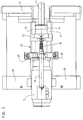
- eine Seitenansicht einer Einrichtung zur Behandlung und/oder Entfernung von Spritzteilen,
- Fig. 3
- eine Draufsicht auf die Einrichtung gemäß Fig. 2,
- Fig. 4
- eine Ansicht auf die bewegliche Formträgerplatte, wobei die Schließeinheit geschnitten ist,
- Fig. 5
- eine Darstellung gemäß Fig. 2 mit einer unmittelbaren Befestigung der Einrichtung am Formträger,
- Fig. 6
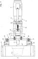
- eine spritzgießseitige Anordnung der Einrichtung in einer Seitenansicht,
- Fig. 7
- eine Draufsicht auf die Anordnung gemäß Fig. 6,
- Fig. 8
- eine Seitenansicht auf eine Formschließeinheit mit zwei daran befestigten Einrichtungen.
Claims (11)
- Formschließeinheit (F) mit einer Einrichtung (13) zur Behandlung und/oder Entfernung von Spritzteilen (10) an einer Spritzgießmaschine zur Verarbeitung plastifizierbarer Materialien miteinem stationären Formträger (11),einem beweglichen Formträger (12), der auf den stationären Formträger (11) zu und von diesem weg bewegbar ist,einem zwischen beweglichem und stationärem Formträger gebildeten Formspannraum (R), geeignet zur Aufnahme eines Werkzeuges (M) mit einem Formhohlraum (14) zur Herstellung der Spritzteile (10),einem Abstützelement, mit dem sich die Einrichtung (13) an der Formschließeinheit abstüzt,einem Betätigungselement für die Einrichtung (13), durch das ein in das Werkzeug (M) bis zum Formhohlraum (14) linear eindringendes Behandlungselement (17) betätigbar ist, falls eine Behandlung und/oder Entfernung von Spritzteilen (10) erforderlich ist,einer elektromechanischen Antriebseinheit (A) zum Antrieb des Betätigungselements,einer zumindest aus Antriebseinheit (A), Abstützelement und Betätigungselement gebildeten, in sich geschlossenen und für sich von der Formschließeinheit (F) abnehmbaren baulichen Einheit, wobei sich die Einrichtung über das Abstützelement am Werkzeug (M), am stationären Formträger oder am beweglichen Formträger abstützt, dadurch gekennzeichnet, daß die Antriebseinheit (A) ein das Betätigungselement zumindest teilweise in sich aufnehmender Hohlwellenmotor ist.
- Formschließeinheit nach Anspruch 1, dadurch gekennzeichnet, daß die bauliche Einheit eine Wegmeßeinrichtung (19) aufweist, durch deren Signal die Antriebseinheit (A) steuer- oder regelbar ist.
- Formschließeinheit nach Anspruch 1, dadurch gekennzeichnet, daß die Antriebseinheit (A) an einer als Abstützelement ausgebildeten Halteplatte (20) befestigt ist, die über Bolzen (21) auf Abstand vom Werkzeug gehalten ist.
- Formschließeinheit nach Anspruch 3, dadurch gekennzeichnet, daß die Antriebseinheit (A) über die Bolzen (21) am beweglichen Formträger (12) festlegbar ist.
- Formschließeinheit nach Anspruch 3, dadurch gekennzeichnet, daß die Antriebseinheit (A) über die Bolzen (21) am stationären Formträger (11) festlegbar ist.
- Formschließeinheit nach Anspruch 3, dadurch gekennzeichnet, daß auf den Bolzen (21) eine Lagerung (22) für das linear bewegte Betätigungselement geführt ist, an dem vorzugsweise auch der Kupplungsbereich (K) für das Behandlungselement (17) angeordnet ist.
- Formschließeinheit nach Anspruch 1, dadurch gekennzeichnet, daß die bauliche Einheit am stationären Formträger (11) befestigbar ist.
- Formschließeinheit nach Anspruch 7, dadurch gekennzeichnet, daß die bauliche Einheit über eine Führungsholme (26) einer Spritzgießeinheit (S) nachahmende Tragkonstruktion (T) an Anschlußorganen (25) im Bereich des stationären Formträgers (11) festlegbar ist, die für die Befestigung der Führungsholme (26) vorgesehen sind, und daß das Betätigungselement durch die Einspritzöffnung (11a) bis in den Formspannraum (R) eindringt.
- Formschließeinheit nach Anspruch 1, dadurch gekennzeichnet, daß bei Verwendung der Einrichtung (13) als Ausschraubeinrichtung eine Spindel (15) der Antriebseinheit (A) rotiert.
- Formschließeinheit nach einem der vorhergehenden Ansprüche, dadurch gekennzeichnet, daß die Einrichtung (13) als Kernzieher verwendet wird.
- Formschließeinheit nach einem der vorhergehenden Ansprüche, dadurch gekennzeichnet, daß die Einrichtung (13) als Auswerfer verwendet wird.
Applications Claiming Priority (3)
| Application Number | Priority Date | Filing Date | Title |
|---|---|---|---|
| DE19536567A DE19536567C2 (de) | 1995-10-02 | 1995-10-02 | Formschließeinheit mit einer Einrichtung zur Behandlung und/oder Entfernung von Spritzteilen |
| DE19536567 | 1995-10-02 | ||
| PCT/DE1996/001767 WO1997012741A2 (de) | 1995-10-02 | 1996-09-13 | Formschliesseinheit mit einer einrichtung zur entfernung von spritzteilen |
Publications (2)
| Publication Number | Publication Date |
|---|---|
| EP0853537A2 EP0853537A2 (de) | 1998-07-22 |
| EP0853537B1 true EP0853537B1 (de) | 1999-06-30 |
Family
ID=7773738
Family Applications (1)
| Application Number | Title | Priority Date | Filing Date |
|---|---|---|---|
| EP96943001A Expired - Lifetime EP0853537B1 (de) | 1995-10-02 | 1996-09-13 | Formschliesseinheit mit einer einrichtung zur entfernung von spritzteilen |
Country Status (7)
| Country | Link |
|---|---|
| US (1) | US6109904A (de) |
| EP (1) | EP0853537B1 (de) |
| JP (1) | JP3881695B2 (de) |
| AT (1) | ATE181692T1 (de) |
| CA (1) | CA2231451C (de) |
| DE (2) | DE19536567C2 (de) |
| WO (1) | WO1997012741A2 (de) |
Families Citing this family (8)
| Publication number | Priority date | Publication date | Assignee | Title |
|---|---|---|---|---|
| DE19847298C2 (de) | 1998-10-14 | 2000-11-02 | Karl Hehl | Spritzgießmaschine mit einem mehrere Antriebsgruppen umfassenden modularen Aufbau |
| AU7651700A (en) * | 1999-11-11 | 2001-06-06 | Dr. Reinold Hagen Stiftung | Blow-molding machine |
| JP3406561B2 (ja) * | 2000-03-21 | 2003-05-12 | 住友重機械工業株式会社 | 射出成形機の製品突出し装置 |
| DE10022192A1 (de) * | 2000-05-03 | 2001-11-15 | Mannesmann Ag | Einrichtung zum Entfernen von Spritzgießteilen |
| DE102010046275A1 (de) * | 2010-09-22 | 2012-03-22 | Netstal-Maschinen Ag | Universelle Hilfssteuerung für eine Spritzgießmaschine |
| TW201213090A (en) * | 2010-09-23 | 2012-04-01 | Hon Hai Prec Ind Co Ltd | Double mandril device of the injection molding machine |
| DE102011114963A1 (de) * | 2011-10-06 | 2013-04-11 | Kraussmaffei Technologies Gmbh | Spritzgußteil-Auswerfvorrichtung und Kunststoff-Spritzgießmaschine mit einer solchen Spritzgußteil-Auswerfvorrichtung |
| KR101509911B1 (ko) * | 2012-09-03 | 2015-04-07 | 엥글 오스트리아 게엠베하 | 사출성형기의 폐쇄유니트 |
Family Cites Families (8)
| Publication number | Priority date | Publication date | Assignee | Title |
|---|---|---|---|---|
| DE1962663C3 (de) * | 1969-12-13 | 1979-08-30 | Karl 7298 Lossburg Hehl | Vorrichtung zur Herstellung von mit Innengewinde versehenen Spritzlingen in Spritzgießformen |
| DE3243991C2 (de) * | 1982-11-27 | 1985-01-10 | Karl 7298 Loßburg Hehl | Formschließeinheit mit einer Auswerfer-Antriebsvorrichtung |
| DE8233362U1 (de) * | 1982-11-27 | 1986-01-02 | Hehl, Karl, 7298 Loßburg | In der Formschließeinheit einer Kunststoff-Spritzgießmaschine angeordnete Auswerfer-Antriebsvorrichtung |
| DE3739059A1 (de) * | 1987-11-17 | 1989-05-24 | Deutsche Forsch Luft Raumfahrt | Vorrichtung zur umwandlung einer drehbewegung in eine axialbewegung |
| DE4228140A1 (de) * | 1992-08-25 | 1994-03-03 | Battenfeld Kunststoffmasch | Auswerfereinheit für Spritzgießmaschinen |
| ATE149115T1 (de) * | 1992-08-25 | 1997-03-15 | Battenfeld Kunststoffmasch | Schliesseinheit für formwerkzeuge von spritzgiessmaschinen |
| DE4409822C2 (de) * | 1994-02-19 | 1997-06-12 | Procontrol Ag | Antrieb für wenigstens eine linear bewegbare Achse einer Spritzgießmaschine |
| US5711971A (en) * | 1995-08-25 | 1998-01-27 | The Whitaker Corporation | Reconfigurable mold having traveling ejector system |
-
1995
- 1995-10-02 DE DE19536567A patent/DE19536567C2/de not_active Expired - Fee Related
-
1996
- 1996-09-13 US US09/043,938 patent/US6109904A/en not_active Expired - Lifetime
- 1996-09-13 CA CA002231451A patent/CA2231451C/en not_active Expired - Fee Related
- 1996-09-13 AT AT96943001T patent/ATE181692T1/de active
- 1996-09-13 JP JP51387197A patent/JP3881695B2/ja not_active Expired - Fee Related
- 1996-09-13 DE DE59602341T patent/DE59602341D1/de not_active Expired - Lifetime
- 1996-09-13 WO PCT/DE1996/001767 patent/WO1997012741A2/de active IP Right Grant
- 1996-09-13 EP EP96943001A patent/EP0853537B1/de not_active Expired - Lifetime
Also Published As
| Publication number | Publication date |
|---|---|
| US6109904A (en) | 2000-08-29 |
| ATE181692T1 (de) | 1999-07-15 |
| DE59602341D1 (de) | 1999-08-05 |
| DE19536567A1 (de) | 1997-04-03 |
| DE19536567C2 (de) | 1998-12-17 |
| EP0853537A2 (de) | 1998-07-22 |
| JPH11512664A (ja) | 1999-11-02 |
| WO1997012741A2 (de) | 1997-04-10 |
| CA2231451A1 (en) | 1997-04-10 |
| JP3881695B2 (ja) | 2007-02-14 |
| WO1997012741A3 (de) | 1997-10-30 |
| CA2231451C (en) | 2006-10-10 |
Similar Documents
| Publication | Publication Date | Title |
|---|---|---|
| EP1673208B1 (de) | Horizontal-spritzgiessmaschine mit dreheinrichtung | |
| DE3720214C2 (de) | Verfahren zum Spritzgießen von Gegenständen und Spritzgießmaschine zur Durchführung des Verfahrens | |
| EP0249703A2 (de) | Spritzgiessmaschine mit mindestens zwei Plastifizier- und Einspritzeinheiten | |
| EP0508277B1 (de) | Verschiebe- und/oder Stellkraft-Antriebsvorrichtung für Spritzgiessmaschinen | |
| EP1278624B1 (de) | Einrichtung zum entfernen von spritzgiessteilen | |
| EP0853537B1 (de) | Formschliesseinheit mit einer einrichtung zur entfernung von spritzteilen | |
| EP0714749B1 (de) | Einrichtung zum Entfernen von gegossenen Formteilen | |
| EP3655225B1 (de) | Formschliesseinheit für eine spritzgiessmaschine | |
| EP0585671B1 (de) | Auswerfereinheit für Spritzgiessmaschinen | |
| EP0583718B1 (de) | Kunststoff-Spritzgiessmaschine | |
| DE102004050311B4 (de) | Schließeinheit für ein Spritzgießmaschine mit Etagenwerkzeug | |
| DE2734414A1 (de) | Spritzgiessanlage | |
| LU88768A1 (de) | Vorrichtung zum Spritzpraegen von insbesondere scheibenfoermigen Kunststoffartikeln in einer Spritzgiessmaschine | |
| EP1199147B1 (de) | Etagenwerkzeug zum Spritzgiessen von Kunststoffteilen | |
| EP1848577B1 (de) | Spritzgiessmaschine zur verarbeitung von kunststoffen | |
| EP1384562A1 (de) | Entnahmeeinrichtung für eine Kunststoff-Spritzgiessmaschine | |
| DE4418452A1 (de) | Metallgießform und Metall-Formgießvorrichtung | |
| EP0657271B1 (de) | Vorrichtung zum Auswerfen von Spritzgussteilen | |
| EP0580975A1 (de) | Vorrichtung zum Erzeugen der Düsenanlagekraft, mit der eine Düse eines von einem Spindelantrieb angetriebenen Plastifizier- und Einspritzaggregats gegen die auf die feststehende Formaufspannplatte aufgespannte Formhälfte ansteht | |
| DE19631432C2 (de) | Spritzgießmaschine zur Verarbeitung von Kunststoffen und anderen plastifizierbaren Massen | |
| WO2002057062A1 (de) | Auswerfvorrichtung für eine formmaschine | |
| DE202016106485U1 (de) | Spritzgießmaschine und Platten zur Anordnung in einer Spritzgießmaschine | |
| DE102004027224A1 (de) | Thermoformmaschine und Verfahren zum Betreiben einer Thermoformmaschine | |
| EP0549928A1 (de) | Gussmaschine, insbesondere Spritzgussmaschine | |
| DE1914280A1 (de) | Anordnung bei einer Spritzgussmaschine zur Herstellung eines Mehrkomponentengussteils |
Legal Events
| Date | Code | Title | Description |
|---|---|---|---|
| PUAI | Public reference made under article 153(3) epc to a published international application that has entered the european phase |
Free format text: ORIGINAL CODE: 0009012 |
|
| 17P | Request for examination filed |
Effective date: 19980321 |
|
| AK | Designated contracting states |
Kind code of ref document: A2 Designated state(s): AT CH DE FR GB IT LI |
|
| GRAG | Despatch of communication of intention to grant |
Free format text: ORIGINAL CODE: EPIDOS AGRA |
|
| 17Q | First examination report despatched |
Effective date: 19980904 |
|
| GRAG | Despatch of communication of intention to grant |
Free format text: ORIGINAL CODE: EPIDOS AGRA |
|
| GRAH | Despatch of communication of intention to grant a patent |
Free format text: ORIGINAL CODE: EPIDOS IGRA |
|
| GRAH | Despatch of communication of intention to grant a patent |
Free format text: ORIGINAL CODE: EPIDOS IGRA |
|
| GRAA | (expected) grant |
Free format text: ORIGINAL CODE: 0009210 |
|
| AK | Designated contracting states |
Kind code of ref document: B1 Designated state(s): AT CH DE FR GB IT LI |
|
| REF | Corresponds to: |
Ref document number: 181692 Country of ref document: AT Date of ref document: 19990715 Kind code of ref document: T |
|
| REG | Reference to a national code |
Ref country code: CH Ref legal event code: EP |
|
| GBT | Gb: translation of ep patent filed (gb section 77(6)(a)/1977) |
Effective date: 19990630 |
|
| REF | Corresponds to: |
Ref document number: 59602341 Country of ref document: DE Date of ref document: 19990805 |
|
| REG | Reference to a national code |
Ref country code: CH Ref legal event code: NV Representative=s name: LUCHS & PARTNER PATENTANWAELTE |
|
| ITF | It: translation for a ep patent filed |
Owner name: CALVANI SALVI E VERONELLI S.R.L. |
|
| ET | Fr: translation filed | ||
| PLBE | No opposition filed within time limit |
Free format text: ORIGINAL CODE: 0009261 |
|
| STAA | Information on the status of an ep patent application or granted ep patent |
Free format text: STATUS: NO OPPOSITION FILED WITHIN TIME LIMIT |
|
| 26N | No opposition filed | ||
| PGFP | Annual fee paid to national office [announced via postgrant information from national office to epo] |
Ref country code: GB Payment date: 20010823 Year of fee payment: 6 |
|
| REG | Reference to a national code |
Ref country code: GB Ref legal event code: IF02 |
|
| PG25 | Lapsed in a contracting state [announced via postgrant information from national office to epo] |
Ref country code: GB Free format text: LAPSE BECAUSE OF NON-PAYMENT OF DUE FEES Effective date: 20020913 |
|
| GBPC | Gb: european patent ceased through non-payment of renewal fee |
Effective date: 20020913 |
|
| REG | Reference to a national code |
Ref country code: FR Ref legal event code: ST Effective date: 20110531 |
|
| PG25 | Lapsed in a contracting state [announced via postgrant information from national office to epo] |
Ref country code: FR Free format text: LAPSE BECAUSE OF NON-PAYMENT OF DUE FEES Effective date: 20100930 |
|
| PGFP | Annual fee paid to national office [announced via postgrant information from national office to epo] |
Ref country code: FR Payment date: 20091005 Year of fee payment: 14 |
|
| PGFP | Annual fee paid to national office [announced via postgrant information from national office to epo] |
Ref country code: IT Payment date: 20120926 Year of fee payment: 17 |
|
| PG25 | Lapsed in a contracting state [announced via postgrant information from national office to epo] |
Ref country code: IT Free format text: LAPSE BECAUSE OF NON-PAYMENT OF DUE FEES Effective date: 20130913 |
|
| PGFP | Annual fee paid to national office [announced via postgrant information from national office to epo] |
Ref country code: CH Payment date: 20140922 Year of fee payment: 19 Ref country code: DE Payment date: 20140919 Year of fee payment: 19 |
|
| PGFP | Annual fee paid to national office [announced via postgrant information from national office to epo] |
Ref country code: AT Payment date: 20140922 Year of fee payment: 19 |
|
| REG | Reference to a national code |
Ref country code: DE Ref legal event code: R119 Ref document number: 59602341 Country of ref document: DE |
|
| REG | Reference to a national code |
Ref country code: CH Ref legal event code: PL |
|
| REG | Reference to a national code |
Ref country code: AT Ref legal event code: MM01 Ref document number: 181692 Country of ref document: AT Kind code of ref document: T Effective date: 20150913 |
|
| PG25 | Lapsed in a contracting state [announced via postgrant information from national office to epo] |
Ref country code: CH Free format text: LAPSE BECAUSE OF NON-PAYMENT OF DUE FEES Effective date: 20150930 Ref country code: DE Free format text: LAPSE BECAUSE OF NON-PAYMENT OF DUE FEES Effective date: 20160401 Ref country code: LI Free format text: LAPSE BECAUSE OF NON-PAYMENT OF DUE FEES Effective date: 20150930 |
|
| PG25 | Lapsed in a contracting state [announced via postgrant information from national office to epo] |
Ref country code: AT Free format text: LAPSE BECAUSE OF NON-PAYMENT OF DUE FEES Effective date: 20150913 |