EP0714827B1 - Schalter für Getriebe an Fahrrädern - Google Patents
Schalter für Getriebe an Fahrrädern Download PDFInfo
- Publication number
- EP0714827B1 EP0714827B1 EP95113973A EP95113973A EP0714827B1 EP 0714827 B1 EP0714827 B1 EP 0714827B1 EP 95113973 A EP95113973 A EP 95113973A EP 95113973 A EP95113973 A EP 95113973A EP 0714827 B1 EP0714827 B1 EP 0714827B1
- Authority
- EP
- European Patent Office
- Prior art keywords
- spring
- detent
- travel
- over
- housing
- Prior art date
- Legal status (The legal status is an assumption and is not a legal conclusion. Google has not performed a legal analysis and makes no representation as to the accuracy of the status listed.)
- Expired - Lifetime
Links
Images

Classifications
-
- B—PERFORMING OPERATIONS; TRANSPORTING
- B62—LAND VEHICLES FOR TRAVELLING OTHERWISE THAN ON RAILS
- B62K—CYCLES; CYCLE FRAMES; CYCLE STEERING DEVICES; RIDER-OPERATED TERMINAL CONTROLS SPECIALLY ADAPTED FOR CYCLES; CYCLE AXLE SUSPENSIONS; CYCLE SIDECARS, FORECARS, OR THE LIKE
- B62K23/00—Rider-operated controls specially adapted for cycles, i.e. means for initiating control operations, e.g. levers, grips
- B62K23/02—Rider-operated controls specially adapted for cycles, i.e. means for initiating control operations, e.g. levers, grips hand actuated
- B62K23/04—Twist grips
-
- B—PERFORMING OPERATIONS; TRANSPORTING
- B62—LAND VEHICLES FOR TRAVELLING OTHERWISE THAN ON RAILS
- B62M—RIDER PROPULSION OF WHEELED VEHICLES OR SLEDGES; POWERED PROPULSION OF SLEDGES OR SINGLE-TRACK CYCLES; TRANSMISSIONS SPECIALLY ADAPTED FOR SUCH VEHICLES
- B62M25/00—Actuators for gearing speed-change mechanisms specially adapted for cycles
- B62M25/02—Actuators for gearing speed-change mechanisms specially adapted for cycles with mechanical transmitting systems, e.g. cables, levers
- B62M25/04—Actuators for gearing speed-change mechanisms specially adapted for cycles with mechanical transmitting systems, e.g. cables, levers hand actuated
Definitions
- the invention relates to a switch for actuating derailleur gears Bicycles according to the preamble of claims 1 and 7.
- a switch for derailleur known, which has a rotary ring 44 with a Cable suspension 43 and handle ends 50 and a handlebar-fixed housing 22 with Has recesses for a spring ring 28, which with lugs 26 with Recesses 46 cooperates in the rotating ring 44.
- This spring ring 28 is in accordance with Fig. 2 in one piece and two parts according to FIG. 4, wherein it is one of the parts is the detent spring 29 which is relative to the second ring part 29 ' a small circular path can be rotated.
- This relative rotatability serves according to claim 6 of the possibility of the switching path from a detent to next against the spring force of the derailleur to make it small To increase relative rotation, whereby a switchover path is generated, which at Transfer of the chain from the small to the larger sprocket as before is of great benefit for the switching quality.
- An improvement can be achieved by introducing an override spring, the as a compression spring in the formwork space between the detent spring and the second ring part or the housing would be attached.
- the advantage is one defined position of the detent spring in the rest position of the switching system and in the Switching precision after switching from small to large Sprocket reached by the instant cancellation of the override condition becomes.
- a switch is also known from document US-A-5 197 927 according to the preamble of claims 1 and 7.
- a detent switch for actuating one Derailleur K it consists of a housing 11, which with a Part of a bicycle is firmly connected, one within this housing 11 Slidable locking element 13, which on the one hand with a manual operation and on the other hand with the derailleur to be switched on the bicycle for the purpose Change of translation is connected.
- the present 1 is a handle part of a Handlebar arranged around rotary handle switch, the manual override H with the locking element 13 is connected.
- the locking element 13 with the first end of a control wire of a Bowden cable connected during the second end of the control wire is connected to the derailleur K.
- the Locking element 13 has catches 19 into which a nose 5 of a catch spring 3 intervenes.
- the detent spring 3 is designed in a bow shape and supports in this case with two projections 21 on the housing 11, whereby the nose 5 is biased against the locking element 13.
- the detent spring 3 lies in an arcuate recess in the housing 11, whereby it is set in the circumferential direction.
- This definition includes a additional game, namely the switchover path 17, within which the Latch spring 3 can move back and forth in the circumferential direction.
- a transfer spring 7 is provided, which is in one piece with the Detent spring 3 connected, but also as a separate switching spring 7b in the form of a Belleville washer or as a separate spring 7c in the form of a spiral spring can be arranged.
- a stop 9 can be arranged, the The path of the transfer spring 7 is precisely limited and the transfer path 17 is defined.
- a detent spring 3 ' is described, which is also bow-shaped is formed and consists of a steel strip material as a leaf spring.
- This Latch spring 3 ' also has a holding force to complement the Snap 19 in the locking element 13 on a nose 5 ', which from a bias results, which is produced by two projections 21 'and 21' ', which are at the Support housing 11.
- the detent spring 3' is in one piece with one Connection spring 7 'connected, which lie against the flank on the housing 11 can.
- recesses 7' ' be arranged, which weaken the tape material locally and a softer Spring rate compared to the non-weakened band material of the detent spring 3 ' allow.
- the operation of the detent switch 1 can be explained in a schematic sketch according to Figure 2.
- the identically named names with the same numbers are added a ". If the latching element 13a in the housing 11a is pulled by the manual control H in the direction of the manual control H, the chain should be transferred from a smaller to a larger sprocket. Because of the less climbing ability of the chain in this switching direction, the desired Position of the derailleur K switched by the overlap path 17, which increases the angle of ascent of the chain compared to the larger sprocket and the switchover takes place that the user only switches to the next resistance in order to let go after that, without realizing it or even intending to do so, has used the switchover path 17. According to Fig.
- the latching element can be connected to the housing 11a via a compensation spring 15a be what has the advantage t that the switching movement in the direction of the larger sprocket is facilitated, since the compensation spring 15a acts as a tension spring of the spring force from the parallelogram of the derailleur K
- the compensation spring 15a can also be omitted, since the actual switching process between the locking element 13a and the locking spring 3a is not affected. If the latching element 13a is then moved further in the direction of manual actuation H, the overlap spring 7a is first pressed together by the latching nose 5a and the overlap travel 17 is consumed by the latching nose 5a on the latching spring 3a.
Landscapes
- Engineering & Computer Science (AREA)
- Mechanical Engineering (AREA)
- Chemical & Material Sciences (AREA)
- Combustion & Propulsion (AREA)
- Transportation (AREA)
- Lock And Its Accessories (AREA)
- Storing, Repeated Paying-Out, And Re-Storing Of Elongated Articles (AREA)
- Mechanical Control Devices (AREA)
Description
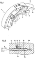
- Fig. 1
- einen perspektivischen Ausschnitt eines Schalters mit einem Gehäuse, einem Rastelement und einer Rastfeder mit einer Überschaltfeder;
- Fig. 2
- eine schematische Darstellung der am Zusammenkommen einer Überschaltwirkung beteiligten Elemente;
- Fig. 3
- eine Variante der Überschaltfeder als Tellerfeder;
- Fig. 4
- eine weitere Variante der Überschaltfeder als Spiralfeder.
- Fi.g 5
- einen perspektivischen Ausschnitt gem. Fig. 1 mit einer Rastfeder aus Stahl-Band-Material und integrierter Überschaltfeder.

Claims (8)
- Schalter für eine Kettenschaltung für Fahrräder, umfassend ein Gehäuse (11), ein Rastelement (13), das sowohl mit der Handbetätigung (H) als auch mit der Kettenschaltung (K) verbunden ist sowie eine Rastfeder (3) aus federelastischem Kunststoffmaterial, deren Nase (5) mit Rasten (19) des Rastelements (13) zusammenwirkt und zwischen dem Gehäuse (11) und der Rastfeder (3) einen Überschaltweg (17) aufweist, wobei die Rastfeder (3) in einer Aussparung des Gehäuses (11) angeordnet ist, dadurch gekennzeichnet daß in der Aussparung zusätzlich zu der Rastfeder (3) in Bewegungsrichtung gesehen nachgeordnet eine Überschaltfeder (7) angeordnet ist, die dort eine Vorspannung zwischen das Gehäuse (11) und die Rastfeder (3) legen kann und auf Block drückbar ist.
- Schalter nach Anspruch 1, dadurch gekennzeichnet, daß der Federweg der Überschaltfeder (7) dem vorgesehenen Überschaltweg (17) an der Kettenschaltung entspricht.
- Schalter nach Anspruch 1, dadurch gekennzeichnet, daß die Überschaltfeder (7) einteilig mit der Rastfeder (3) verbunden ist.
- Schalter nach Anspruch 3, dadurch gekennzeichnet, daß die Rastfeder (3) einen Anschlag (9) aufweist, der den Überschaltweg (17) durch Zusammenwirken mit der Überschaltfeder (7) begrenzt.
- Schalter nach Anspruch 1, dadurch gekennzeichnet, daß die Überschaltfeder (7b) als Tellerfeder ausgebildet ist.
- Schalter nach Anspruch 1, dadurch gekennzeichnet, daß die Überschaltfeder (7c) als Spiralfeder ausgebildet ist.
- Schalter für eine Kettenschaltung für Fahrräder, umfassend ein Gehäuse (11), in Rastelement (13), das sowohl mit der Handbetätigung (H) als auch mit der Kettenschaltung (K) verbunden ist, sowie eine Rastfeder (3'), deren Nase (5') mit Rasten (19) des Rastelements (13) zusammenwirkt und zwischen dem Gehäuse (11) und der Rastfeder (3') einen Überschaltweg (17) aufweist wobei, die Rastfeder (3') in einer Aussparung des Gehäuses (11) angeordnet ist, dadurch gekennzeichnet daß in der Aussparung zusätzlich zu der Rastfeder (3') in Bewegungsrichtung gesehen nachgeordnet eine mit der Rastfeder (3') einteilig verbundene Überschaltfeder (7') angeordnet ist, die dort eine Vorspannung zwischen dem Gehäuse (11) und die Rastfeder (3') legen kann.
- Schalter nach Anspruch 7, dadurch gekennzeichnet, daß die Rastfeder (3') aus Stahl-Band-Material besteht.
Applications Claiming Priority (2)
| Application Number | Priority Date | Filing Date | Title |
|---|---|---|---|
| DE4442952 | 1994-12-02 | ||
| DE4442952A DE4442952C1 (de) | 1994-12-02 | 1994-12-02 | Schalter für Getriebe an Fahrrädern |
Publications (3)
| Publication Number | Publication Date |
|---|---|
| EP0714827A2 EP0714827A2 (de) | 1996-06-05 |
| EP0714827A3 EP0714827A3 (de) | 1996-11-20 |
| EP0714827B1 true EP0714827B1 (de) | 1998-12-16 |
Family
ID=6534749
Family Applications (1)
| Application Number | Title | Priority Date | Filing Date |
|---|---|---|---|
| EP95113973A Expired - Lifetime EP0714827B1 (de) | 1994-12-02 | 1995-09-06 | Schalter für Getriebe an Fahrrädern |
Country Status (2)
| Country | Link |
|---|---|
| EP (1) | EP0714827B1 (de) |
| DE (2) | DE4442952C1 (de) |
Families Citing this family (2)
| Publication number | Priority date | Publication date | Assignee | Title |
|---|---|---|---|---|
| US5676020A (en) * | 1995-06-30 | 1997-10-14 | Sram Corporation | Hand-rotatable bicycle gear shift actuator with overshift return |
| DE19613575A1 (de) * | 1996-04-04 | 1997-10-09 | Fichtel & Sachs Ag | Rastenschalter für ein Fahrradgetriebe |
Family Cites Families (5)
| Publication number | Priority date | Publication date | Assignee | Title |
|---|---|---|---|---|
| JPS5631519Y2 (de) * | 1977-04-23 | 1981-07-27 | ||
| US4793821A (en) * | 1986-01-17 | 1988-12-27 | Engineered Transitions Company, Inc. | Vibration resistant electrical coupling |
| FR2657062B1 (fr) * | 1990-01-12 | 1992-04-30 | Sachs Ind Sa | Dispositif de commande a indexation pour derailleur de cycle. |
| US5197927B1 (en) * | 1991-03-20 | 2000-10-17 | Sram Corp | Bicycle derailleur cable actuating system |
| JPH0844450A (ja) * | 1994-03-07 | 1996-02-16 | Sram Corp | 回動型グリップ作動装置及びその回り止め機構 |
-
1994
- 1994-12-02 DE DE4442952A patent/DE4442952C1/de not_active Expired - Fee Related
-
1995
- 1995-09-06 EP EP95113973A patent/EP0714827B1/de not_active Expired - Lifetime
- 1995-09-06 DE DE59504554T patent/DE59504554D1/de not_active Expired - Fee Related
Also Published As
| Publication number | Publication date |
|---|---|
| EP0714827A2 (de) | 1996-06-05 |
| EP0714827A3 (de) | 1996-11-20 |
| DE59504554D1 (de) | 1999-01-28 |
| DE4442952C1 (de) | 1996-02-22 |
Similar Documents
| Publication | Publication Date | Title |
|---|---|---|
| DE69700390T2 (de) | Fahrrad-Gangschaltungshebel | |
| DE69203639T2 (de) | Geschwindigkeitssteuergerät für ein Fahrrad. | |
| DE60224156T2 (de) | Steuervorrichtung für eine Fahrradschaltvorrichtung | |
| DE69014159T2 (de) | Schaltvorrichtung für Fahrradgangschaltung. | |
| DE69004614T2 (de) | Gangschaltung für ein Fahrrad. | |
| DE69423175T2 (de) | Vorderer Umwerfer für ein Fahrrad | |
| DE69130806T2 (de) | Fahrrad-Geschwindigkeitssteuergerät mit Steuerdraht | |
| DE69202179T2 (de) | Brems- und Gangwechselsteuereinrichtung für ein Fahrrad. | |
| DE69116516T2 (de) | Fahrradgeschwindigkeitssteuergerät | |
| DE60200771T2 (de) | Elektrisch gesteuerte Getriebe für die Steuerung eines Kettenräderwechselgetriebes eines Fahrrads | |
| DE69702149T2 (de) | Hebelverlängerung für eine Fahrradgangschaltung | |
| DE60223863T2 (de) | Vorrichtung zur Betätigung einer Gangschaltung | |
| DE69500508T2 (de) | Rastfeder für Drehhandgriff-Betätigungseinrichtung | |
| DE69314768T2 (de) | Öffnungsvorrichtung einer kappe | |
| DE2705809A1 (de) | Kettenfuehrer fuer eine vordere kettenschaltung fuer fahrraeder | |
| DE4413610A1 (de) | Steuereinrichtung einer Fahrrad-Gangschaltung | |
| DE2657721C3 (de) | Kettenschaltung für ein Fahrrad | |
| DE2948378A1 (de) | Tretlager-kettenradschaltung fuer fahrraeder | |
| DE2719241A1 (de) | Umwerfer fuer eine fahrrad-kettenschaltung | |
| DE2526314A1 (de) | Fahrradgangschaltung | |
| DE2830493C2 (de) | Vorderer Kettenumwerfer für eine Fahrrad-Kettenschaltung | |
| WO2000007871A1 (de) | Schalter für fahrradgetriebe | |
| DE4342460A1 (de) | Schalthebelbaugruppe für ein Getriebe eines Kraftfahrzeugs | |
| DE102004014035A1 (de) | Fahrrad-Gangschaltungseinrichtung | |
| DE69116037T2 (de) | STEUERHEBEL FüR WECHSELGETRIEBE FüR FAHRRÄDER |
Legal Events
| Date | Code | Title | Description |
|---|---|---|---|
| PUAI | Public reference made under article 153(3) epc to a published international application that has entered the european phase |
Free format text: ORIGINAL CODE: 0009012 |
|
| AK | Designated contracting states |
Kind code of ref document: A2 Designated state(s): DE FR GB NL SE |
|
| PUAL | Search report despatched |
Free format text: ORIGINAL CODE: 0009013 |
|
| AK | Designated contracting states |
Kind code of ref document: A3 Designated state(s): DE FR GB NL SE |
|
| 17P | Request for examination filed |
Effective date: 19961206 |
|
| RAP1 | Party data changed (applicant data changed or rights of an application transferred) |
Owner name: MANNESMANN SACHS AKTIENGESELLSCHAFT |
|
| GRAG | Despatch of communication of intention to grant |
Free format text: ORIGINAL CODE: EPIDOS AGRA |
|
| GRAG | Despatch of communication of intention to grant |
Free format text: ORIGINAL CODE: EPIDOS AGRA |
|
| GRAH | Despatch of communication of intention to grant a patent |
Free format text: ORIGINAL CODE: EPIDOS IGRA |
|
| RAP1 | Party data changed (applicant data changed or rights of an application transferred) |
Owner name: SRAM DEUTSCHLAND GMBH |
|
| 17Q | First examination report despatched |
Effective date: 19980630 |
|
| GRAH | Despatch of communication of intention to grant a patent |
Free format text: ORIGINAL CODE: EPIDOS IGRA |
|
| GRAA | (expected) grant |
Free format text: ORIGINAL CODE: 0009210 |
|
| AK | Designated contracting states |
Kind code of ref document: B1 Designated state(s): DE FR GB NL SE |
|
| GBT | Gb: translation of ep patent filed (gb section 77(6)(a)/1977) |
Effective date: 19981221 |
|
| REF | Corresponds to: |
Ref document number: 59504554 Country of ref document: DE Date of ref document: 19990128 |
|
| ET | Fr: translation filed | ||
| PLBE | No opposition filed within time limit |
Free format text: ORIGINAL CODE: 0009261 |
|
| STAA | Information on the status of an ep patent application or granted ep patent |
Free format text: STATUS: NO OPPOSITION FILED WITHIN TIME LIMIT |
|
| 26N | No opposition filed | ||
| PGFP | Annual fee paid to national office [announced via postgrant information from national office to epo] |
Ref country code: GB Payment date: 20000814 Year of fee payment: 6 |
|
| PGFP | Annual fee paid to national office [announced via postgrant information from national office to epo] |
Ref country code: NL Payment date: 20000824 Year of fee payment: 6 |
|
| PGFP | Annual fee paid to national office [announced via postgrant information from national office to epo] |
Ref country code: SE Payment date: 20000825 Year of fee payment: 6 |
|
| PGFP | Annual fee paid to national office [announced via postgrant information from national office to epo] |
Ref country code: FR Payment date: 20000831 Year of fee payment: 6 |
|
| PG25 | Lapsed in a contracting state [announced via postgrant information from national office to epo] |
Ref country code: GB Free format text: LAPSE BECAUSE OF NON-PAYMENT OF DUE FEES Effective date: 20010906 |
|
| PG25 | Lapsed in a contracting state [announced via postgrant information from national office to epo] |
Ref country code: SE Free format text: LAPSE BECAUSE OF NON-PAYMENT OF DUE FEES Effective date: 20010907 |
|
| PG25 | Lapsed in a contracting state [announced via postgrant information from national office to epo] |
Ref country code: NL Free format text: LAPSE BECAUSE OF NON-PAYMENT OF DUE FEES Effective date: 20020401 |
|
| EUG | Se: european patent has lapsed |
Ref document number: 95113973.2 |
|
| PG25 | Lapsed in a contracting state [announced via postgrant information from national office to epo] |
Ref country code: FR Free format text: LAPSE BECAUSE OF NON-PAYMENT OF DUE FEES Effective date: 20020531 |
|
| NLV4 | Nl: lapsed or anulled due to non-payment of the annual fee |
Effective date: 20020401 |
|
| REG | Reference to a national code |
Ref country code: FR Ref legal event code: ST |
|
| NLV4 | Nl: lapsed or anulled due to non-payment of the annual fee |
Effective date: 20020401 |
|
| PGFP | Annual fee paid to national office [announced via postgrant information from national office to epo] |
Ref country code: DE Payment date: 20080929 Year of fee payment: 14 |
|
| PG25 | Lapsed in a contracting state [announced via postgrant information from national office to epo] |
Ref country code: DE Free format text: LAPSE BECAUSE OF NON-PAYMENT OF DUE FEES Effective date: 20100401 |