EP0713232A1 - Schaltkammer eines Lastschalters - Google Patents
Schaltkammer eines Lastschalters Download PDFInfo
- Publication number
- EP0713232A1 EP0713232A1 EP95410128A EP95410128A EP0713232A1 EP 0713232 A1 EP0713232 A1 EP 0713232A1 EP 95410128 A EP95410128 A EP 95410128A EP 95410128 A EP95410128 A EP 95410128A EP 0713232 A1 EP0713232 A1 EP 0713232A1
- Authority
- EP
- European Patent Office
- Prior art keywords
- movable contact
- chamber
- arc
- cut
- chamber according
- Prior art date
- Legal status (The legal status is an assumption and is not a legal conclusion. Google has not performed a legal analysis and makes no representation as to the accuracy of the status listed.)
- Granted
Links
- 230000015572 biosynthetic process Effects 0.000 claims abstract description 9
- 238000000926 separation method Methods 0.000 claims abstract description 6
- 239000007789 gas Substances 0.000 claims abstract description 5
- 230000008033 biological extinction Effects 0.000 claims abstract description 4
- 239000000919 ceramic Substances 0.000 claims description 2
- 239000002184 metal Substances 0.000 claims description 2
- 238000001816 cooling Methods 0.000 abstract description 6
- 238000011536 re-plating Methods 0.000 description 3
- 230000008034 disappearance Effects 0.000 description 1
- 238000006073 displacement reaction Methods 0.000 description 1
- 238000001704 evaporation Methods 0.000 description 1
- 230000008020 evaporation Effects 0.000 description 1
- 230000035515 penetration Effects 0.000 description 1
Images


Classifications
-
- H—ELECTRICITY
- H01—ELECTRIC ELEMENTS
- H01H—ELECTRIC SWITCHES; RELAYS; SELECTORS; EMERGENCY PROTECTIVE DEVICES
- H01H9/00—Details of switching devices, not covered by groups H01H1/00 - H01H7/00
- H01H9/52—Cooling of switch parts
-
- H—ELECTRICITY
- H01—ELECTRIC ELEMENTS
- H01H—ELECTRIC SWITCHES; RELAYS; SELECTORS; EMERGENCY PROTECTIVE DEVICES
- H01H9/00—Details of switching devices, not covered by groups H01H1/00 - H01H7/00
- H01H9/30—Means for extinguishing or preventing arc between current-carrying parts
- H01H9/34—Stationary parts for restricting or subdividing the arc, e.g. barrier plate
- H01H9/346—Details concerning the arc formation chamber
Definitions
- the invention relates to the breaking chamber of an electric circuit breaker, comprising an arc-forming chamber containing a fixed contact and a movable contact, which, at the time of their separation form an arc between them, said formation chamber communicating with the entrance to a second chamber, called the arc extinction chamber.
- circuit breakers in particular miniature circuit breakers, it has been observed that after the switching of the arc, and the displacement of the latter in the breaking chamber in the direction of the extinguishing chamber, a current of a few amperes remains on the mobile contact. This low residual current is at the origin of a phenomenon called "reclaking" which is defined by the disappearance in a few microseconds of the arc present in the extinguishing chamber and appearance of the latter at the movable contact.
- the present invention solves this problem and proposes an electrical circuit breaker cut-out chamber in which the risks of re-plating are considerably reduced.
- the present invention relates to a breaking chamber of an electric circuit breaker comprising an arc forming chamber containing a fixed contact and a movable contact, which, at the time of their separation form an arc between them.
- the formation chamber communicates with the entrance to a second so-called arc extinguishing chamber, and the breaking chamber is characterized in that it further comprises at least one cooler placed inside the formation of an arc so as to cool the gases present around the movable contact after the switching of the arc.
- the above-mentioned coolers are placed around the movable contact.
- the above-mentioned coolers are placed between the movable contact and the aforementioned extinguishing chamber, at a predetermined distance from said movable contact.
- the aforementioned coolers consist of plates or tubes.
- the above-mentioned coolers comprise two sets of plates parallel to each other, arranged on either side of the movable contact.
- these plates extend substantially parallel to the movable contact.
- the above-mentioned coolers comprise two sets of tubes parallel to each other, arranged on either side of the movable contact.
- these tubes extend substantially perpendicular to the movable contact.
- the above-mentioned coolers are made of metal or ceramic.
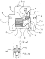
- Figures 1, 2 and 3 are three schematic sectional views, respectively illustrating three particular embodiments of the invention.
- FIGS. 1a, 2a and 3a are schematic side views, illustrating the shape and the arrangement of the coolers corresponding respectively to FIGS. 1, 2 and 3.
- a pole 1 of miniature circuit breaker comprising an insulating housing B, having on its front face an operating handle 2 and on its two narrow lateral faces 3, 4, connection terminals 5, 6.
- a movable contact 7 At the inside the housing B are housed, as is known per se, a movable contact 7 and a fixed contact 8.
- the movable contact 7 is controlled by a control mechanism (not shown) connecting the aforementioned lever 2 to the movable contact 7 for the contact closure.
- a thermal trip device and an electromagnetic trip device (not shown), capable of causing, in the event of an overload or short-circuit, an automatic opening of the contacts.
- the lower part of the housing B contains a breaking chamber 9 constituted by a first arc-forming chamber 10, communicating with the inlet of a second chamber 11, called the arc extinction chamber, comprising separators 13 constituted by a stack of plates (or sheets) which extend parallel to the base 12 of the housing B.
- the movable contact 7 extends substantially perpendicularly to the plane of the plates 13, so as to draw an arc between the contacts 7, 8, during their separation, the initial direction of which is substantially parallel to the plates 13.
- the abovementioned breaking chamber 9 is delimited laterally by arcing horns 14, 15 respectively connected electrically to the two aforementioned terminals 5, 6. These arcing horns 14, 15 are arranged so as to pick up the arc drawn between the contacts 7, 8 during their separation.
- cooling elements 16 are placed around the movable contact 7 and are intended to cool the hot gases present around the movable contact 7 after the switching of the arc.
- These coolers 16 consist of two sets 17a, 17b of plates 17 parallel to each other, said sets being disposed respectively on either side of the movable contact 7.
- these cooling elements 16, or coolers are constituted by two sets 18a, 18b of tubes 18 parallel to each other, said sets 18a, 18b being arranged on either side of the contact mobile 7.
- these tubes 18, instead of being arranged around the movable contact 7, are placed in the arc-forming chamber 10, at a certain distance from said contact 7, for example at same distance between the separators 13 and the movable contact 7. It will be noted that in this case, the two sets of tubes 18a, 18b will be separated by a distance a greater than the width of the movable contact 7. In these three embodiments, the large exchange surface of the coolers 16 results in significant cooling of the gas.
Landscapes
- Arc-Extinguishing Devices That Are Switches (AREA)
- Circuit Breakers (AREA)
Applications Claiming Priority (2)
| Application Number | Priority Date | Filing Date | Title |
|---|---|---|---|
| FR9414006A FR2727240B1 (fr) | 1994-11-18 | 1994-11-18 | Chambre de coupure d'un disjoncteur electrique |
| FR9414006 | 1994-11-18 |
Publications (2)
| Publication Number | Publication Date |
|---|---|
| EP0713232A1 true EP0713232A1 (de) | 1996-05-22 |
| EP0713232B1 EP0713232B1 (de) | 1999-07-28 |
Family
ID=9469049
Family Applications (1)
| Application Number | Title | Priority Date | Filing Date |
|---|---|---|---|
| EP19950410128 Expired - Lifetime EP0713232B1 (de) | 1994-11-18 | 1995-11-10 | Schaltkammer eines Lastschalters |
Country Status (4)
| Country | Link |
|---|---|
| EP (1) | EP0713232B1 (de) |
| DE (1) | DE69511046T2 (de) |
| ES (1) | ES2135025T3 (de) |
| FR (1) | FR2727240B1 (de) |
Cited By (1)
| Publication number | Priority date | Publication date | Assignee | Title |
|---|---|---|---|---|
| WO2011119148A1 (en) * | 2010-03-22 | 2011-09-29 | Siemens Industry, Inc. | Arc formation chamber with improved arc compression for circuit breaker. |
Families Citing this family (2)
| Publication number | Priority date | Publication date | Assignee | Title |
|---|---|---|---|---|
| DE102007001802B4 (de) * | 2006-12-22 | 2010-02-25 | Abb Ag | Elektrisches Schaltgerät |
| DE102017204942B4 (de) * | 2017-03-23 | 2022-01-20 | Siemens Aktiengesellschaft | Elektromechanisches Schutzschaltgerät |
Citations (4)
| Publication number | Priority date | Publication date | Assignee | Title |
|---|---|---|---|---|
| DE1922747A1 (de) * | 1969-05-03 | 1970-11-05 | Bbc Brown Boveri & Cie | Lichtbogenkammer |
| EP0183145A2 (de) * | 1984-11-27 | 1986-06-04 | Asea Brown Boveri Aktiengesellschaft | Elektrisches Schaltgerät, insbesondere Leitungsschutzschalter |
| FR2575861A1 (fr) * | 1985-01-07 | 1986-07-11 | Merlin Gerin | Disjoncteur electrique miniature a chambre de formation d'arc |
| DE3619241A1 (de) * | 1986-06-07 | 1987-12-10 | Kloeckner Moeller Elektrizit | Loescheinrichtung fuer einen leitungsschutzschalter |
-
1994
- 1994-11-18 FR FR9414006A patent/FR2727240B1/fr not_active Expired - Fee Related
-
1995
- 1995-11-10 DE DE1995611046 patent/DE69511046T2/de not_active Expired - Lifetime
- 1995-11-10 EP EP19950410128 patent/EP0713232B1/de not_active Expired - Lifetime
- 1995-11-10 ES ES95410128T patent/ES2135025T3/es not_active Expired - Lifetime
Patent Citations (4)
| Publication number | Priority date | Publication date | Assignee | Title |
|---|---|---|---|---|
| DE1922747A1 (de) * | 1969-05-03 | 1970-11-05 | Bbc Brown Boveri & Cie | Lichtbogenkammer |
| EP0183145A2 (de) * | 1984-11-27 | 1986-06-04 | Asea Brown Boveri Aktiengesellschaft | Elektrisches Schaltgerät, insbesondere Leitungsschutzschalter |
| FR2575861A1 (fr) * | 1985-01-07 | 1986-07-11 | Merlin Gerin | Disjoncteur electrique miniature a chambre de formation d'arc |
| DE3619241A1 (de) * | 1986-06-07 | 1987-12-10 | Kloeckner Moeller Elektrizit | Loescheinrichtung fuer einen leitungsschutzschalter |
Cited By (2)
| Publication number | Priority date | Publication date | Assignee | Title |
|---|---|---|---|---|
| US8164018B2 (en) | 2009-03-23 | 2012-04-24 | Siemens Industry, Inc. | Circuit breaker arc chambers and methods for operating same |
| WO2011119148A1 (en) * | 2010-03-22 | 2011-09-29 | Siemens Industry, Inc. | Arc formation chamber with improved arc compression for circuit breaker. |
Also Published As
| Publication number | Publication date |
|---|---|
| FR2727240A1 (fr) | 1996-05-24 |
| DE69511046D1 (de) | 1999-09-02 |
| EP0713232B1 (de) | 1999-07-28 |
| ES2135025T3 (es) | 1999-10-16 |
| FR2727240B1 (fr) | 1996-12-13 |
| DE69511046T2 (de) | 2000-02-17 |
Similar Documents
| Publication | Publication Date | Title |
|---|---|---|
| EP2061051B1 (de) | Lichtbogenkammer und Schutzschalter, der mit einer solchen Lichtbogenkammer ausgestattet ist | |
| EP0236202B1 (de) | Stromunterbrechungsapparat mit statischem Schalter und Schutzlastschalter | |
| EP0042778B1 (de) | Einpol- und Nulleiter-Kleinschalter | |
| FR2807565A1 (fr) | Pole pour un disjoncteur electrique limiteur de basse tension de puissance et disjoncteur muni d'un tel pole | |
| EP0206882B1 (de) | Niederspannungsschalter mit Unterbrechung | |
| FR2803686A1 (fr) | Pole pour disjoncteur electrique, muni d'une chambre d'extinction d'arc a ecrans dielectriques | |
| EP0589779A1 (de) | Leitungsschutzschalter mit magnetischer Blasschleife | |
| EP0713232B1 (de) | Schaltkammer eines Lastschalters | |
| EP0649155B1 (de) | Doppelte Lichtbogenlaufschiene für die Lichtbogenleitkammer eines Schutzschalters | |
| EP1667179B1 (de) | Elektrische Schaltvorrichtung mit Wiederverwendung von Schaltgasen | |
| FR3141796A1 (fr) | Contacteur électrique à recirculation des gaz ionisés | |
| EP0148058B1 (de) | Miniaturlastschalter mit dielektrischen Eigenschaften | |
| EP3035363B1 (de) | Lichtbogen-schaltkammer für einen leistungsschalter, und leistungsschalter, der eine solche kammer umfasst | |
| EP0619592B1 (de) | Elektrischer Schutzschalter mit elektrodynamischer Kontaktabstossung und mit Doppellöschkammern | |
| EP1764811B1 (de) | Trennschalter mit einer verkleineten Lichtbogenlöschkammer | |
| EP1667180B1 (de) | Elektrische Schaltvorrichtung und Lichtbogenlöschkammer mit Deionisierungsflügeln | |
| EP1103996B1 (de) | Abschaltvorrichtung für ein Schaltgerät | |
| FR2734080A1 (fr) | Appareil interrupteur electrique d'installation | |
| FR2531565A1 (fr) | Dispositifs modulaires de limitation de courant | |
| EP0047696A2 (de) | Kleinstselbstschalter mit Lichtbogenkontakten | |
| FR2733352A1 (fr) | Pole pour appareil limiteur de courant | |
| EP0462026A1 (de) | Selbstschalter mit Auslass für Schaltgase | |
| FR2584230A1 (fr) | Chambre d'extinction d'arc pour disjoncteur a basse tension a coupure dans l'air | |
| EP0646938A1 (de) | Schutzschalter mit verbesserte Lichtbogenkammer | |
| FR2613872A1 (fr) | Disjoncteur electrique miniature a boitier moule |
Legal Events
| Date | Code | Title | Description |
|---|---|---|---|
| PUAI | Public reference made under article 153(3) epc to a published international application that has entered the european phase |
Free format text: ORIGINAL CODE: 0009012 |
|
| AK | Designated contracting states |
Kind code of ref document: A1 Designated state(s): DE ES GB IT |
|
| 17P | Request for examination filed |
Effective date: 19961108 |
|
| 17Q | First examination report despatched |
Effective date: 19970423 |
|
| GRAG | Despatch of communication of intention to grant |
Free format text: ORIGINAL CODE: EPIDOS AGRA |
|
| GRAG | Despatch of communication of intention to grant |
Free format text: ORIGINAL CODE: EPIDOS AGRA |
|
| GRAH | Despatch of communication of intention to grant a patent |
Free format text: ORIGINAL CODE: EPIDOS IGRA |
|
| GRAH | Despatch of communication of intention to grant a patent |
Free format text: ORIGINAL CODE: EPIDOS IGRA |
|
| GRAA | (expected) grant |
Free format text: ORIGINAL CODE: 0009210 |
|
| AK | Designated contracting states |
Kind code of ref document: B1 Designated state(s): DE ES GB IT |
|
| REF | Corresponds to: |
Ref document number: 69511046 Country of ref document: DE Date of ref document: 19990902 |
|
| RAP2 | Party data changed (patent owner data changed or rights of a patent transferred) |
Owner name: SCHNEIDER ELECTRIC INDUSTRIES SA |
|
| REG | Reference to a national code |
Ref country code: ES Ref legal event code: FG2A Ref document number: 2135025 Country of ref document: ES Kind code of ref document: T3 |
|
| ITF | It: translation for a ep patent filed | ||
| GBT | Gb: translation of ep patent filed (gb section 77(6)(a)/1977) |
Effective date: 19991102 |
|
| PLBE | No opposition filed within time limit |
Free format text: ORIGINAL CODE: 0009261 |
|
| STAA | Information on the status of an ep patent application or granted ep patent |
Free format text: STATUS: NO OPPOSITION FILED WITHIN TIME LIMIT |
|
| 26N | No opposition filed | ||
| REG | Reference to a national code |
Ref country code: GB Ref legal event code: IF02 |
|
| REG | Reference to a national code |
Ref country code: DE Ref legal event code: R084 Ref document number: 69511046 Country of ref document: DE Effective date: 20111228 |
|
| PGFP | Annual fee paid to national office [announced via postgrant information from national office to epo] |
Ref country code: DE Payment date: 20121112 Year of fee payment: 18 |
|
| PGFP | Annual fee paid to national office [announced via postgrant information from national office to epo] |
Ref country code: GB Payment date: 20131106 Year of fee payment: 19 |
|
| PGFP | Annual fee paid to national office [announced via postgrant information from national office to epo] |
Ref country code: IT Payment date: 20131114 Year of fee payment: 19 Ref country code: ES Payment date: 20131011 Year of fee payment: 19 |
|
| PG25 | Lapsed in a contracting state [announced via postgrant information from national office to epo] |
Ref country code: DE Free format text: LAPSE BECAUSE OF NON-PAYMENT OF DUE FEES Effective date: 20140603 |
|
| REG | Reference to a national code |
Ref country code: DE Ref legal event code: R119 Ref document number: 69511046 Country of ref document: DE Effective date: 20140603 |
|
| GBPC | Gb: european patent ceased through non-payment of renewal fee |
Effective date: 20141110 |
|
| PG25 | Lapsed in a contracting state [announced via postgrant information from national office to epo] |
Ref country code: GB Free format text: LAPSE BECAUSE OF NON-PAYMENT OF DUE FEES Effective date: 20141110 |
|
| REG | Reference to a national code |
Ref country code: ES Ref legal event code: FD2A Effective date: 20151229 |
|
| PG25 | Lapsed in a contracting state [announced via postgrant information from national office to epo] |
Ref country code: IT Free format text: LAPSE BECAUSE OF NON-PAYMENT OF DUE FEES Effective date: 20141110 |
|
| PG25 | Lapsed in a contracting state [announced via postgrant information from national office to epo] |
Ref country code: ES Free format text: LAPSE BECAUSE OF NON-PAYMENT OF DUE FEES Effective date: 20141111 |