EP0712759A1 - Verkleidungselemente für Fahrzeuge und Verfahren zu deren Herstellung - Google Patents
Verkleidungselemente für Fahrzeuge und Verfahren zu deren Herstellung Download PDFInfo
- Publication number
- EP0712759A1 EP0712759A1 EP95308111A EP95308111A EP0712759A1 EP 0712759 A1 EP0712759 A1 EP 0712759A1 EP 95308111 A EP95308111 A EP 95308111A EP 95308111 A EP95308111 A EP 95308111A EP 0712759 A1 EP0712759 A1 EP 0712759A1
- Authority
- EP
- European Patent Office
- Prior art keywords
- core member
- main body
- surface skin
- skin member
- trim main
- Prior art date
- Legal status (The legal status is an assumption and is not a legal conclusion. Google has not performed a legal analysis and makes no representation as to the accuracy of the status listed.)
- Ceased
Links
Images


Classifications
-
- B—PERFORMING OPERATIONS; TRANSPORTING
- B60—VEHICLES IN GENERAL
- B60R—VEHICLES, VEHICLE FITTINGS, OR VEHICLE PARTS, NOT OTHERWISE PROVIDED FOR
- B60R13/00—Elements for body-finishing, identifying, or decorating; Arrangements or adaptations for advertising purposes
- B60R13/02—Internal Trim mouldings ; Internal Ledges; Wall liners for passenger compartments; Roof liners
- B60R13/0237—Side or rear panels
- B60R13/0243—Doors
-
- B—PERFORMING OPERATIONS; TRANSPORTING
- B60—VEHICLES IN GENERAL
- B60J—WINDOWS, WINDSCREENS, NON-FIXED ROOFS, DOORS, OR SIMILAR DEVICES FOR VEHICLES; REMOVABLE EXTERNAL PROTECTIVE COVERINGS SPECIALLY ADAPTED FOR VEHICLES
- B60J5/00—Doors
- B60J5/04—Doors arranged at the vehicle sides
- B60J5/0412—Lower door structure
- B60J5/0416—Assembly panels to be installed in doors as a module with components, e.g. lock or window lifter, attached thereto
-
- B—PERFORMING OPERATIONS; TRANSPORTING
- B60—VEHICLES IN GENERAL
- B60R—VEHICLES, VEHICLE FITTINGS, OR VEHICLE PARTS, NOT OTHERWISE PROVIDED FOR
- B60R13/00—Elements for body-finishing, identifying, or decorating; Arrangements or adaptations for advertising purposes
- B60R13/02—Internal Trim mouldings ; Internal Ledges; Wall liners for passenger compartments; Roof liners
-
- B—PERFORMING OPERATIONS; TRANSPORTING
- B29—WORKING OF PLASTICS; WORKING OF SUBSTANCES IN A PLASTIC STATE IN GENERAL
- B29C—SHAPING OR JOINING OF PLASTICS; SHAPING OF MATERIAL IN A PLASTIC STATE, NOT OTHERWISE PROVIDED FOR; AFTER-TREATMENT OF THE SHAPED PRODUCTS, e.g. REPAIRING
- B29C2793/00—Shaping techniques involving a cutting or machining operation
- B29C2793/009—Shaping techniques involving a cutting or machining operation after shaping
-
- B—PERFORMING OPERATIONS; TRANSPORTING
- B29—WORKING OF PLASTICS; WORKING OF SUBSTANCES IN A PLASTIC STATE IN GENERAL
- B29C—SHAPING OR JOINING OF PLASTICS; SHAPING OF MATERIAL IN A PLASTIC STATE, NOT OTHERWISE PROVIDED FOR; AFTER-TREATMENT OF THE SHAPED PRODUCTS, e.g. REPAIRING
- B29C51/00—Shaping by thermoforming, i.e. shaping sheets or sheet like preforms after heating, e.g. shaping sheets in matched moulds or by deep-drawing; Apparatus therefor
- B29C51/08—Deep drawing or matched-mould forming, i.e. using mechanical means only
-
- B—PERFORMING OPERATIONS; TRANSPORTING
- B29—WORKING OF PLASTICS; WORKING OF SUBSTANCES IN A PLASTIC STATE IN GENERAL
- B29C—SHAPING OR JOINING OF PLASTICS; SHAPING OF MATERIAL IN A PLASTIC STATE, NOT OTHERWISE PROVIDED FOR; AFTER-TREATMENT OF THE SHAPED PRODUCTS, e.g. REPAIRING
- B29C51/00—Shaping by thermoforming, i.e. shaping sheets or sheet like preforms after heating, e.g. shaping sheets in matched moulds or by deep-drawing; Apparatus therefor
- B29C51/10—Forming by pressure difference, e.g. vacuum
-
- B—PERFORMING OPERATIONS; TRANSPORTING
- B29—WORKING OF PLASTICS; WORKING OF SUBSTANCES IN A PLASTIC STATE IN GENERAL
- B29C—SHAPING OR JOINING OF PLASTICS; SHAPING OF MATERIAL IN A PLASTIC STATE, NOT OTHERWISE PROVIDED FOR; AFTER-TREATMENT OF THE SHAPED PRODUCTS, e.g. REPAIRING
- B29C63/00—Lining or sheathing, i.e. applying preformed layers or sheathings of plastics; Apparatus therefor
- B29C63/02—Lining or sheathing, i.e. applying preformed layers or sheathings of plastics; Apparatus therefor using sheet or web-like material
- B29C63/04—Lining or sheathing, i.e. applying preformed layers or sheathings of plastics; Apparatus therefor using sheet or web-like material by folding, winding, bending or the like
-
- B—PERFORMING OPERATIONS; TRANSPORTING
- B29—WORKING OF PLASTICS; WORKING OF SUBSTANCES IN A PLASTIC STATE IN GENERAL
- B29C—SHAPING OR JOINING OF PLASTICS; SHAPING OF MATERIAL IN A PLASTIC STATE, NOT OTHERWISE PROVIDED FOR; AFTER-TREATMENT OF THE SHAPED PRODUCTS, e.g. REPAIRING
- B29C65/00—Joining or sealing of preformed parts, e.g. welding of plastics materials; Apparatus therefor
- B29C65/02—Joining or sealing of preformed parts, e.g. welding of plastics materials; Apparatus therefor by heating, with or without pressure
- B29C65/04—Dielectric heating, e.g. high-frequency welding, i.e. radio frequency welding of plastic materials having dielectric properties, e.g. PVC
-
- B—PERFORMING OPERATIONS; TRANSPORTING
- B29—WORKING OF PLASTICS; WORKING OF SUBSTANCES IN A PLASTIC STATE IN GENERAL
- B29C—SHAPING OR JOINING OF PLASTICS; SHAPING OF MATERIAL IN A PLASTIC STATE, NOT OTHERWISE PROVIDED FOR; AFTER-TREATMENT OF THE SHAPED PRODUCTS, e.g. REPAIRING
- B29C66/00—General aspects of processes or apparatus for joining preformed parts
- B29C66/70—General aspects of processes or apparatus for joining preformed parts characterised by the composition, physical properties or the structure of the material of the parts to be joined; Joining with non-plastics material
- B29C66/71—General aspects of processes or apparatus for joining preformed parts characterised by the composition, physical properties or the structure of the material of the parts to be joined; Joining with non-plastics material characterised by the composition of the plastics material of the parts to be joined
-
- B—PERFORMING OPERATIONS; TRANSPORTING
- B29—WORKING OF PLASTICS; WORKING OF SUBSTANCES IN A PLASTIC STATE IN GENERAL
- B29L—INDEXING SCHEME ASSOCIATED WITH SUBCLASS B29C, RELATING TO PARTICULAR ARTICLES
- B29L2031/00—Other particular articles
- B29L2031/30—Vehicles, e.g. ships or aircraft, or body parts thereof
- B29L2031/3005—Body finishings
- B29L2031/3014—Door linings
-
- B—PERFORMING OPERATIONS; TRANSPORTING
- B60—VEHICLES IN GENERAL
- B60R—VEHICLES, VEHICLE FITTINGS, OR VEHICLE PARTS, NOT OTHERWISE PROVIDED FOR
- B60R13/00—Elements for body-finishing, identifying, or decorating; Arrangements or adaptations for advertising purposes
- B60R13/02—Internal Trim mouldings ; Internal Ledges; Wall liners for passenger compartments; Roof liners
- B60R2013/0281—Internal Trim mouldings ; Internal Ledges; Wall liners for passenger compartments; Roof liners made of a plurality of visible parts
-
- B—PERFORMING OPERATIONS; TRANSPORTING
- B60—VEHICLES IN GENERAL
- B60R—VEHICLES, VEHICLE FITTINGS, OR VEHICLE PARTS, NOT OTHERWISE PROVIDED FOR
- B60R13/00—Elements for body-finishing, identifying, or decorating; Arrangements or adaptations for advertising purposes
- B60R13/02—Internal Trim mouldings ; Internal Ledges; Wall liners for passenger compartments; Roof liners
- B60R2013/0293—Connection or positioning of adjacent panels
-
- B—PERFORMING OPERATIONS; TRANSPORTING
- B60—VEHICLES IN GENERAL
- B60Y—INDEXING SCHEME RELATING TO ASPECTS CROSS-CUTTING VEHICLE TECHNOLOGY
- B60Y2200/00—Type of vehicle
- B60Y2200/10—Road Vehicles
- B60Y2200/11—Passenger cars; Automobiles
-
- Y—GENERAL TAGGING OF NEW TECHNOLOGICAL DEVELOPMENTS; GENERAL TAGGING OF CROSS-SECTIONAL TECHNOLOGIES SPANNING OVER SEVERAL SECTIONS OF THE IPC; TECHNICAL SUBJECTS COVERED BY FORMER USPC CROSS-REFERENCE ART COLLECTIONS [XRACs] AND DIGESTS
- Y10—TECHNICAL SUBJECTS COVERED BY FORMER USPC
- Y10T—TECHNICAL SUBJECTS COVERED BY FORMER US CLASSIFICATION
- Y10T428/00—Stock material or miscellaneous articles
- Y10T428/24—Structurally defined web or sheet [e.g., overall dimension, etc.]
- Y10T428/2419—Fold at edge
- Y10T428/24264—Particular fold structure [e.g., beveled, etc.]
-
- Y—GENERAL TAGGING OF NEW TECHNOLOGICAL DEVELOPMENTS; GENERAL TAGGING OF CROSS-SECTIONAL TECHNOLOGIES SPANNING OVER SEVERAL SECTIONS OF THE IPC; TECHNICAL SUBJECTS COVERED BY FORMER USPC CROSS-REFERENCE ART COLLECTIONS [XRACs] AND DIGESTS
- Y10—TECHNICAL SUBJECTS COVERED BY FORMER USPC
- Y10T—TECHNICAL SUBJECTS COVERED BY FORMER US CLASSIFICATION
- Y10T428/00—Stock material or miscellaneous articles
- Y10T428/24—Structurally defined web or sheet [e.g., overall dimension, etc.]
- Y10T428/24479—Structurally defined web or sheet [e.g., overall dimension, etc.] including variation in thickness
- Y10T428/24612—Composite web or sheet
-
- Y—GENERAL TAGGING OF NEW TECHNOLOGICAL DEVELOPMENTS; GENERAL TAGGING OF CROSS-SECTIONAL TECHNOLOGIES SPANNING OVER SEVERAL SECTIONS OF THE IPC; TECHNICAL SUBJECTS COVERED BY FORMER USPC CROSS-REFERENCE ART COLLECTIONS [XRACs] AND DIGESTS
- Y10—TECHNICAL SUBJECTS COVERED BY FORMER USPC
- Y10T—TECHNICAL SUBJECTS COVERED BY FORMER US CLASSIFICATION
- Y10T428/00—Stock material or miscellaneous articles
- Y10T428/24—Structurally defined web or sheet [e.g., overall dimension, etc.]
- Y10T428/24777—Edge feature
-
- Y—GENERAL TAGGING OF NEW TECHNOLOGICAL DEVELOPMENTS; GENERAL TAGGING OF CROSS-SECTIONAL TECHNOLOGIES SPANNING OVER SEVERAL SECTIONS OF THE IPC; TECHNICAL SUBJECTS COVERED BY FORMER USPC CROSS-REFERENCE ART COLLECTIONS [XRACs] AND DIGESTS
- Y10—TECHNICAL SUBJECTS COVERED BY FORMER USPC
- Y10T—TECHNICAL SUBJECTS COVERED BY FORMER US CLASSIFICATION
- Y10T428/00—Stock material or miscellaneous articles
- Y10T428/24—Structurally defined web or sheet [e.g., overall dimension, etc.]
- Y10T428/24942—Structurally defined web or sheet [e.g., overall dimension, etc.] including components having same physical characteristic in differing degree
Definitions
- the present invention relates to automotive upholstery components such as automotive door trims, rear side trims and so on, and a method for making the same.
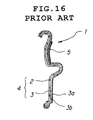
- Figure 16 shows the structure of a conventional automotive door trim 1, which comprises a door trim main body 4 including a resin core member 2 molded into a prescribed shape, and a surface skin member 3 attached to the surface of the resin core member 2 in an overlying relationship, and an ornamental sheet 5, such as a fabric sheet, having a superior appearance and a favorable touch, which is attached to a selected part of the surface of the surface skin member 3 to provide an ornamental effect to the door trim main body 4.
- an ornamental sheet 5 such as a fabric sheet, having a superior appearance and a favorable touch
- a wood fiber mat impregnated with thermo-setting resin serving as a binder is press molded into a prescribed shape by using a hot press molding die assembly provided with a cavity of a prescribed shape to produce a core member 2 having a desired shape. Because this core member 2 is porous, a bonding agent is applied to the surface of the core member 2, and after the bonding agent has dried, the surface skin member 3 is integrally attached to the core member 2 by using a vacuum molding die assembly to complete the step of molding the door trim main body 4.
- the surface skin member 3 consists of a laminated sheet including a top surface layer 3a, for instance, made of a PVC sheet and lined with a foam layer 3b, for instance, made of polyethylene foam.
- a bonding agent is applied to a designated area (corresponding to the ornamental sheet 5) of the surface of the door trim main body 4, and is dried.
- a bonding agent is applied to the reverse surface of the ornamental sheet 5, and is dried.
- the door trim main body 4 and the ornamental sheet 5 are then joined together by using a press die assembly, and the molding step for the door trim 1 is completed.
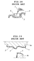
- Figure 18 shows the step of applying the bonding agent to the door trim main body 4 by using a spraying gun 7 while a mask 6 is placed over the surface area of the door trim main body 4 corresponding to the ornamental sheet 5.
- the door trim main body 4 and the ornamental sheet 5 are appropriately placed on the upper and lower dies 8a and 8b of the press die assembly, respectively, after the bonding agent is applied to each of them, and is dried, and the upper and lower dies 8a and 8b of the press die assembly are engaged with each other with the result that the ornamental sheet 5 is integrally attached to the door trim main body 4.
- the ornamental sheet 5 typically made of a fabric sheet is integrally joined to the door trim main body 4 by using a press die assembly 8a and 8b, the fibers of the fabric tends to be swept down, thereby creating the problem of adversely affecting the commercial acceptability thereof due to the loss of favorable appearance and touch.
- the ornamental sheet 5 is required to be properly positioned relative to the door trim main body 4, and even a small offset of the ornamental sheet 5 relative to the door trim main body 4 will soil the surface of the product, thereby lowering the commercial value of the product.
- a primary object of the present invention is to provide automotive upholstery components which have an improved external appearance and are easy to fabricate.
- a second object of the present invention is to provide automotive upholstery components which can be made without using any bonding agent, and is therefore free from the problem of soiling the surface of the finished product.
- a third object of the present invention is to provide automotive upholstery components which can be made without using any bonding agent, and can therefore maintain the working area in a favorable condition with a minimum cost.
- a fourth object of the present invention is to provide automotive upholstery components which can be fabricate without requiring any high precision.
- a fifth object of the present invention is to provide a method for making such automotive upholstery components.
- an automotive upholstery component comprising: a trim main body including a core member molded into a prescribed shape, and a surface skin member attached to a surface of the core member in an overlying relationship, the surface skin member including a top surface layer facing away from the core member and made of a low melting point resin sheet; and an ornamental sheet mounted on a selected area of a surface of the surface skin member, the ornamental sheet being attached to the surface skin member by passing high frequency electric current of a prescribed voltage between the trim main body and the ornamental sheet over an entire bonding surface thereof, and thereby softening the top surface layer of the surface skin member to serve the top surface layer as a bonding agent.
- the material of the core member and the molding process may be freely selected as long as the top surface layer of the surface skin member consists of a low melting point resin sheet.
- the selected area of a surface of the surface skin member may define a recessed surface.
- a peripheral part of the selected area of a surface of the trim main body may be provided with an engagement groove which receives a peripheral edge of the ornamental sheet.
- the core member and the surface skin member of the trim main body are integrally molded by a mold press die assembly or by a cold press die assembly, and the core member and the surface skin member are thereby joined with each other by thermal welding.
- a bonding agent can be entirely eliminated from the process of fabricating the upholstery component.
- the upholstery component of the present invention can be fabricated by a method comprising the steps of: molding the trim main body into a prescribed shape with the surface skin member attached to a surface of the core member; placing the ornamental sheet on a first die half provided with a first electrode half extending over a die surface area corresponding to the ornamental sheet; placing the trim main body on a second die half provided with a second electrode half associated with the first electrode half; and engaging the first and second die halves and supplying high frequency electric current of a prescribed voltage between the first and second electrodes; whereby the top surface layer of a part of the surface skin member corresponding to the ornamental sheet is softened, and the ornamental sheet is attached to the trim main body in an overlying relationship with the top surface layer serving as a bonding agent.
- the molding step for the trim main body may consist of a mold press molding process which essentially consists of placing the surface skin member in a molding die assembly, feeding material for the resin core member into the molding die assembly, and closing the molding die assembly to mold the resin core member into the prescribed shape, whereby the surface skin member is thermally welded onto the surface of the resin core member.
- the molding step for the trim main body may consist of a cold press molding process which essentially consists of placing a thermally softened resin core member and the surface skin member in a cold molding die assembly in an overlying relationship, and closing the cold molding die assembly to mold the resin core member into the prescribed shape, whereby the surface skin member is thermally welded onto the surface of the resin core member.
- the use of a bonding agent can be entirely eliminated from the process of fabricating the upholstery component.
- the peripheral part of the surface skin member can be favorably processed by softening a peripheral part of the reverse surface of the core member and/or a fringe part of the surface skin member by heating, and folding and wrapping the fringe part of the surface skin member around an edge of the core member toward the reverse surface thereof.
- a peripheral part of the surface skin member may be folded back along a periphery thereof around an edge of the core member and toward the reverse surface thereof, and is then ultrasonically welded to the core member.
- a vacuum molding process which essential consists of molding the core member made of porous material into the prescribed shape, applying a bonding agent to at least one of two opposing surfaces of the core member and the surface skin member, and attaching the surface skin member onto the core member by applying vacuum suction through the core member.
- the peripheral edge of the ornamental sheet can be conveniently and economically concealed by pushing it into an engagement groove provided in the trim main body. This can be efficiently achieved when the first die half is provided with a push bar for pushing a peripheral part of the ornamental sheet into the groove when the first and second die halves are engaged with each other.
- the first electrode half may be supported by a spring member on the first die half so as to be resiliently moveable in a direction of engaging the die halves while the push bar is fixedly secured to the first die half.
- the first electrode half along with the push bar may be supported by a spring member on the first die half so as to be resiliently moveable in a direction of engaging the die halves.
- the top surface layer of the surface skin member covering the trim main body consists of a low melting point thermoplastic resin sheet
- the top surface layer of the surface skin member covering the trim main body consists of a low melting point thermoplastic resin sheet
- the bonding agent conventionally used for attaching the ornamental sheet to the trim main body is not required any more so that the steps of applying and drying the bonding agent can be eliminated, and the work area needed for applying the bonding agent can be abolished.
- a cold press molding or a mold press molding for molding the trim main body the core member and the surface skin member can be integrally attached to each other by thermal welding, and the need for the bonding agent can be entirely eliminated for making the product.
- fabric such as cloth is used for the ornamental sheet, because the need for the conventional drying and pressing steps can be eliminated, the favorable quality of the cloth can be maintained.
- the automotive door trim 10 essentially consists of a door trim main body 20 molded into a desired curved shape, and an ornamental sheet 30 attached to a selected surface area of the door trim main body 20. More specifically, the door trim main body 20 consists of a core member 21 which is molded into a prescribed shape by hot press molding a wood fiber mat M impregnated with a binder consisting of thermo-setting resin such as phenol resin, and a surface skin member 22 which is integrally attached to the surface of the core member 21 by virtue of the porosity of the core member 21.
- the surface skin member 21 is provided with a laminated structure consisting of a top surface layer 23 consisting of a low melting point resin sheet such as a PVC sheet, and a foam lining layer 24 made of a material having a suitable cushioning property such as polypropylene foam and polyethylene foam.
- Low melting point as used herein is intended to mean the property of the material, typically a synthetic resin material, to soften or otherwise become adhesive to such an extent as to become capable of attaching to an adjoining member when pressed against it at a relatively low temperature.
- the ornamental sheet 30 comprises a fabric sheet, having suitable design characteristics such as velvet, jersey, tricot and moquette, which is lined with a padding layer 32 made of polyurethane foam or the like, and is intended to give an improved design effect to the product by virtue of the contrast in texture between the surface skin member 22 and the ornamental sheet 30.
- the present invention is characterized by the fact that the ornamental sheet is entirely attached to the door trim main body 20 by high frequency welding, and provides the following advantages.
- the work steps are reduced and simplified by eliminating the steps of applying a bonding agent and drying it.
- the working environment is improved by virtue of the elimination of the use of the bonding agent.
- the texture of the fabric sheet 31 is kept in a favorable condition by eliminating the need for heating and pressing the fabric sheet during the conventionally required step of drying the bonding agent.
- the fabrication cost can be substantially reduced owing to the substantial reduction in the fabrication steps.
- the appearance and design characteristics of the fabric sheet can be improved owing to the prevention of the flattening of the fabric sheet and the soiling of the fabrication sheet, and the working environment can be improved owing to the elimination of the use of the bonding agent.
- the entire surface of the ornamental sheet 30 can be attached to the door trim main body 20 in a substantially firmer fashion as compared to the conventional method of welding only the peripheral part of the ornamental sheet 30.
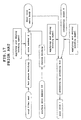
- the fabrication process of the automotive door trim 10 is briefly described in the following with reference to the flow chart of Figure 3.
- the core member 21 is molded into a prescribed shape by hot press molding a wood fiber mat M impregnated with a thermo-setting resin binder, and after a bonding agent is applied to the front surface of the core member 21, the surface skin member 22 is integrally attached to the surface of the core member 21 by vacuum molding, to thereby complete the step of molding the door trim main body 20.
- the door trim main body 20 and the ornamental sheet 30 are integrally joined together by high frequency welding, to thereby complete the step of molding the door trim main body 20.
- a wood fiber mat M impregnated with thermo-setting resin serving as the material for the resin core member 21, is placed between upper and lower mold dies 40 and 41 for hot press molding in an open state.
- the upper die 41 for hot press molding is lowered by a prescribed stroke as illustrated in Figure 5, and the mat M is molded into the resin core member 21 of the prescribed curved shape by the upper and lower dies 40 and 41 for hot press molding.
- the molding conditions for this hot molding process includes the die temperature of 220 °C, and the hot press molding time of 50 seconds.
- a bonding agent is applied to the surface of the core member 21, and is then dried so that it may be used for firmly attaching the core member 21 and the surface skin member 22 together.
- Figures 6 and 7 illustrate the step of attaching the surface skin member 22 by a vacuum bonding step, wherein the core member 21 molded in the preceding step is placed on the die surface of the die assembly 50 for vacuum molding as illustrated in Figure 6.
- the die assembly 50 for vacuum molding is provided with vacuum suction holes 51 arranged in the die surface thereof, and these holes 51 communicate with a vacuum pump 53 via a conduit 52.
- the peripheral part of the surface skin member 22 is retained by a clamping device 54 above the core member 21 which is in turn placed on the die assembly 50 for vacuum molding.
- the die assembly 50 for vacuum molding is lifted by a lifting mechanism not shown in the drawings, and the surface skin member 22 having its peripheral part retained by the clamping device 54 is overlaid over the core member 21 so that the surface skin member 22 may be closely and integrally attached to the surface of the core member 21 by evacuating the air gap between the core member 21 and the surface skin member 22 via the vacuum suction holes 51.
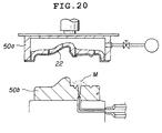
- composite polypropylene resin material having 90 weight parts of polypropylene resin and 10 weight parts of talc may be used as the material for the core member 21, and, as illustrated in Figure 20, while the die assembly for mold press molding is open, the surface skin member 22 consisting of a PVC resin sheet lined with polyethylene foam is placed in the upper die 50a of the die assembly for mold press molding. Then, the upper die 50a for mold press molding is lowered by a prescribed stroke, and when the upper and lower dies 50a and 50b are partly closed, leaving a prescribed clearance therebetween, the composite polypropylene resin material M in semi-molten state is fed to prescribed locations of the die surface of the lower die 50b for mold press molding.
- the upper die 50a is then lowered to its bottom center point, and the core material 21 is mold press molded into a prescribed shape while the surface skin member 22 is thermally and integrally welded to the surface of the core member 21. This completes the molding process for the door trim main body 20.
- the peripheral part of the reverse surface of the core member 21 and/or the folded fringe part of the surface skin member is softened by blowing hot air thereto, and the folded part of the surface skin member 22 is wrapped around the edge of the core member 21 toward the reverse surface thereof. Therefore, no bonding agent is required for attaching the core member and the surface skin member 22, and the processing of the peripheral part also does not require any bonding agent so that the need for a bonding agent is entirely eliminated from the molding step and the periphery processing step for the door trim main body 20.
- cold press molding process may also be employed as illustrated in Figure 21.
- composite polypropylene including polypropylene resin and a wood powder filter mixed at a suitable ratio may be employed as the material for the core member 21, and the surface skin member 22 may consist of a foamed PVC sheet which is lined with a fabric sheet. More specifically, the polypropylene resin mixed with wood powder is extruded into a sheet from a T die extruder, and this blank sheet is softened by heating it to a prescribed temperature before it is placed in the die assembly for cold press molding as the softened material for the core member 21.
- the surface skin member 22 having its peripheral part retained by a clamping device is placed on the surface of the material for the core member 21.
- the upper and lower dies for cold press molding are engaged with each other so that the core member 21 is molded into a prescribed shape while the surface skin member 22 is integrally attached to the surface of the core member 21 by thermal welding.
- the surface skin member 22 is cut out in a slightly oversized dimensions, and is folded back along the periphery thereof around the edge of the core member 21 and toward the reverse surface thereof.
- the folded back portion is then ultrasonically welded to the core member 21, thereby simplifying the edge process for the door trim main body, and eliminating the need for a bonding agent during the molding process for the door trim main body in a similar manner as the case of mold press molding.
- This edge process is equally applicable to the trim main body formed by mold press molding as described above.
- the edge process previously described in connection with the mold press molding can also be applied to the door trim main body formed by cold press molding.
- FIGS 8 and 9 illustrate essential points of the present invention, or the step of mounting the ornamental sheet 30 onto the door trim main body 20.
- a welder upper electrode 61 and a welder lower electrode 71 are disposed between upper and lower dies 60 and 70 for pressing so as to define parts of the dies surfaces of the upper and lower dies 60 and 70, respectively, and the two electrodes 61 and 71 are connected to a high frequency oscillator 80.
- the upper die 60 for pressing is lowered by a prescribed stroke by means of the actuation of a lifting cylinder 62 of the upper die 60 for pressing as illustrated in Figure 9 so that the door trim main body 20 and the ornamental sheet 30 are joined with each other by the upper and lower dies 60 and 70 for pressing.
- the upper and lower dies 60 and 70 for pressing are closed upon each other with the press time period of 7 seconds and the press pressure of 2,750 kgf while high frequency electric current of 1 to 2A and 8,800 to 12,000 volts is applied across the upper and lower electrodes 61 and 71.
- the top surface layer 23 of the surface skin member 22 of the door trim main body 20 is made of a low melting point resin sheet such as a PVC sheet, the top surface layer 23 melts over the entire surface of the ornamental sheet 30 with the result that the molten resin infiltrates into small gaps inside the padding layer 32 of the ornamental sheet 30, and the ornamental sheet 30 is thereby firmly anchored to the door trim main body 20.
- the two parts when mounting the ornamental sheet 30 on a prescribed part of the door trim main body 20, the two parts are secured to each other not by using a bonding agent but by high frequency welding over the entire contact area so that the elimination of the need for a bonding agent not only allows the steps of applying and drying the bonding agent to be eliminated, but also the working environment can be improved, and the appearance of the product can be improved by preventing the soiling of the surface of the product with the bonding agent.
- the molding process for the door trim main body 20 can be made without requiring any bonding agent, and the fabrication of the door trim 10 can be made entirely free from the use of a bonding agent.
- the cloth 31 of the fabric sheet 30 is not required to be pressed with any significant pressure, as conventionally practiced following the step of drying the bonding agent, the surface of the cloth 31 is not flattened, and the ornamental sheet 30 having superior appearance and touch can be firmly attached to a prescribed part of the surface of the door trim main body 20.
- Figure 10 shows a modified embodiment of the automotive door trim 10, which is not different from the first embodiment in that it consists of a door trim main body 20 and an ornamental sheet 30, but the door trim main body 20 is provided with an engagement groove 25 for engaging a peripheral edge 30a of the ornamental sheet 30 therein to enhance the appearance of the peripheral edge of the ornamental sheet 30 by concealing it in the engagement groove 25.
- the ornamental sheet 30 is mounted on the door trim main body 20 by using a push bar 72 which is provided around the outer periphery of the lower die 70 for pressing as illustrated in Figure 11, and the lower die 70 for pressing is disposed vertically moveable by way of spring members 73 consisting of oil springs or the like.
- the electric current supplied from the high frequency welder is applied to a shoulder of the engagement groove 25, and the peripheral edge 30a that is to be pushed into the engagement groove 25 is pushed into the engagement groove 25 by the push bar 72, and is welded to the door trim main body 20.
- the entire area of the ornamental sheet 30, with the exception of the peripheral edge 30a which is to be pushed into the engagement groove 25 of the door trim main body 20, is welded to the door trim main body 20.
- This embodiment provides the same advantage as the first embodiment, and additionally facilitates the work involved in attaching the ornamental sheet because of the increased tolerance in the positional accuracy of the ornamental sheet 30 that is placed on the lower die 70 for pressing. A slight offsetting of the ornamental sheet 30 is accommodated by the peripheral part of the ornamental sheet 30 that is pushed into the engagement groove 25, and would not adversely affect the external appearance of the product. This also contributes to the increase in the productivity.
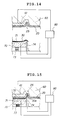
- the modified embodiment illustrated in Figures 12 and 13 involves the use of an integral electrode, and the die surface of the lower die 70 for pressing is itself provided with the push bar 72.
- the modified embodiment illustrated in Figures 14 and 15 involves the use of a separate electrode, and the electrode for the push bar 72 is provided on the outer periphery of the lower die 70 for pressing.
Applications Claiming Priority (2)
| Application Number | Priority Date | Filing Date | Title |
|---|---|---|---|
| JP06285585A JP3090245B2 (ja) | 1994-11-18 | 1994-11-18 | 自動車用内装部品及びその製造方法 |
| JP285585/94 | 1994-11-18 |
Publications (1)
| Publication Number | Publication Date |
|---|---|
| EP0712759A1 true EP0712759A1 (de) | 1996-05-22 |
Family
ID=17693464
Family Applications (1)
| Application Number | Title | Priority Date | Filing Date |
|---|---|---|---|
| EP95308111A Ceased EP0712759A1 (de) | 1994-11-18 | 1995-11-13 | Verkleidungselemente für Fahrzeuge und Verfahren zu deren Herstellung |
Country Status (4)
| Country | Link |
|---|---|
| US (1) | US5695865A (de) |
| EP (1) | EP0712759A1 (de) |
| JP (1) | JP3090245B2 (de) |
| KR (1) | KR0156068B1 (de) |
Cited By (3)
| Publication number | Priority date | Publication date | Assignee | Title |
|---|---|---|---|---|
| FR2907755A1 (fr) * | 2006-10-26 | 2008-05-02 | Faurecia Interieur Ind Snc | Procede de fabrication de plusieurs elements interieurs,et serie d'elements interieurs d'automobile |
| EP2179832A1 (de) * | 2008-10-23 | 2010-04-28 | Intier Automotive Eybl GmbH (Ebergassing) & Co. OHG | Verfahren zur Herstellung eines Innenverkleidungsteils |
| WO2014131918A1 (es) * | 2013-02-28 | 2014-09-04 | Grupo Antolín-Ingeniería, S. A. | Procedimiento para la fabricación de un guarnecido interior de puerta para vehículo, instalación para la fabricación de dicho guarnecido interior de puerta y producto obtenido |
Families Citing this family (35)
| Publication number | Priority date | Publication date | Assignee | Title |
|---|---|---|---|---|
| US5941590A (en) * | 1996-08-02 | 1999-08-24 | Chrysler Corporation | Trim panel with 180 degree periphery edge wrap |
| JPH1076884A (ja) * | 1996-09-06 | 1998-03-24 | Meiwa Ind Co Ltd | 内装化粧部材 |
| US6066217A (en) | 1998-10-22 | 2000-05-23 | Sonics & Materials, Inc. | Method for producing fabric covered panels |
| US6183038B1 (en) | 1999-03-11 | 2001-02-06 | Delphi Technologies, Inc. | Door trim assembly and method of making same |
| JP4102516B2 (ja) * | 1999-05-31 | 2008-06-18 | テイ・エス テック株式会社 | 車両用成形ライニング及びその製造方法 |
| US6171428B1 (en) * | 1999-09-03 | 2001-01-09 | Dongseo Kiyeon Co., Ltd. | Method for fabricating automotive door trims |
| US6422640B2 (en) | 1999-12-30 | 2002-07-23 | Delphi Technologies, Inc. | Door trim panel assembly and method of making |
| US6838027B2 (en) * | 1999-12-30 | 2005-01-04 | Delphi Technologies, Inc. | Method of making an interior trim panel |
| US20020018876A1 (en) * | 2000-03-29 | 2002-02-14 | Kiyoshi Matsuki | Composite molded article and producing method thereof as well as inner mold and metal mold being used for producing cellular molded article in mold pattern having surface skin |
| DE10044760A1 (de) * | 2000-09-09 | 2002-04-04 | Findlay Ind Deutschland Gmbh | Mehrschaliges Innenverkleidungsteil |
| US6723263B2 (en) | 2001-09-25 | 2004-04-20 | Delphi Technologies, Inc. | Apparatus and method of making interior trim panel |
| US6756003B2 (en) | 2002-03-04 | 2004-06-29 | Visteon Global Technologies, Inc. | Method of attaching thermoplastic attachments to a substrate |
| JP3875974B2 (ja) * | 2003-04-11 | 2007-01-31 | 西川ゴム工業株式会社 | 遮音性シート |
| CN101426597B (zh) * | 2003-10-15 | 2012-07-25 | 乔纳森·R·坎彼安 | 用于材料成型和接合的材料固持装置和方法 |
| US8359895B2 (en) * | 2003-10-15 | 2013-01-29 | Modern Body Engineering Corporation | Machine cell with vacuum nest for holding a metal panel during a forming operation |
| US6966594B2 (en) * | 2004-03-01 | 2005-11-22 | Lear Corporation | Vehicle trim panel and method of reducing BSR |
| US20050189775A1 (en) * | 2004-03-01 | 2005-09-01 | De Pue Todd L. | Vehicle trim panel with integrated seal |
| US7364218B2 (en) | 2004-08-25 | 2008-04-29 | International Automotive Components Group North America, Inc. | Automotive hardware carrier and method of making same |
| US20060061134A1 (en) * | 2004-09-21 | 2006-03-23 | Delong Aaron M | Connector having an integrated gasket and method of making the same |
| US7198315B2 (en) * | 2005-03-23 | 2007-04-03 | Lear Corporation | Connector for automotive interior trim |
| US7131685B2 (en) * | 2005-04-01 | 2006-11-07 | Lear Corporation | Automotive door trim panel having an integrated seal |
| JP4765599B2 (ja) * | 2005-12-12 | 2011-09-07 | トヨタ車体株式会社 | 真空成形方法及びその装置 |
| US7338103B2 (en) * | 2006-02-06 | 2008-03-04 | Toyota Motor Engineering & Manufacturing North America, Inc. | Collapsible cover for vehicle interior |
| US20080238063A1 (en) * | 2007-03-30 | 2008-10-02 | Vanderpool Vaughn D | Trim Panel and Method of Manufacturing the Same |
| US7597371B2 (en) * | 2007-05-01 | 2009-10-06 | Toyota Motor Engineering & Manufacturing North America, Inc. | Lead-in for trim assembly |
| US9410026B1 (en) | 2009-05-22 | 2016-08-09 | Columbia Insurance Company | Rebond polyurethane foam comprising reclaimed carpet material and methods for the manufacture of same |
| US9724852B1 (en) | 2009-05-22 | 2017-08-08 | Columbia Insurance Company | High density composites comprising reclaimed carpet material |
| JP5488883B2 (ja) * | 2009-10-16 | 2014-05-14 | トヨタ紡織株式会社 | 車両用内装材 |
| DE102011086450B4 (de) * | 2011-11-16 | 2019-04-04 | Lisa Dräxlmaier GmbH | Verfahren zur Herstellung eines Interieurbauteils für Fahrzeuginnenräume |
| DE102013203408B4 (de) * | 2013-02-28 | 2016-02-11 | Faurecia Innenraum Systeme Gmbh | Verfahren zum Kaschieren eines Bauteils durch ein Kaschierwerkzeug mit einem Kaschierelement |
| DE102013008433B4 (de) * | 2013-05-17 | 2020-12-03 | Lisa Dräxlmaier GmbH | Flächige Vorrichtung zur Beleuchtung der Innenausstattung eines Fahrzeugs |
| KR102115261B1 (ko) | 2019-07-24 | 2020-05-26 | 우정후 | 편직물 제조를 위한 원사 급사 방법 및 장치 |
| KR102328776B1 (ko) * | 2021-01-14 | 2021-11-23 | 주식회사 무등기업 | 도어 트림의 자동화 제조 설비 및 그 제조 방법 |
| KR102524300B1 (ko) * | 2021-01-14 | 2023-04-21 | 주식회사 무등기업 | 기계화된 도어 트림 엣지 랩핑 장치 및 그 제조 방법 |
| KR20240010277A (ko) | 2022-07-15 | 2024-01-23 | 서해원 | 자동차 부품 정밀 가공 시스템 |
Citations (10)
| Publication number | Priority date | Publication date | Assignee | Title |
|---|---|---|---|---|
| JPS55121020A (en) * | 1979-03-09 | 1980-09-17 | Kasai Kogyo Co Ltd | Method of adhering outer layer to polypropylene composite resin sheet |
| JPS61160227A (ja) * | 1985-01-10 | 1986-07-19 | Mikuni Seisakusho:Kk | 高周波ウエルダ−による接合方法及び高周波ウエルダ−電極装置 |
| JPS63199630A (ja) * | 1987-02-16 | 1988-08-18 | Toyota Kako Kk | 自動車用ドアトリムの製造方法 |
| JPH02143839A (ja) * | 1988-11-24 | 1990-06-01 | Takashimaya Nippatsu Kogyo Kk | 自動車内装品の製造法 |
| EP0446411A2 (de) * | 1990-03-14 | 1991-09-18 | Kasai Kogyo Co., Ltd. | Teile im Fahrzeuginnenraum und Verfahren zu ihrer Herstellung |
| EP0495292A1 (de) * | 1991-01-16 | 1992-07-22 | Kasai Kogyo Co., Ltd. | Kraftfahrzeug-Innenverkleidungsteile und Verfahren und Vorrichtung zu deren Herstellung |
| EP0514541A1 (de) * | 1990-12-06 | 1992-11-25 | Kasai Kogyo Co., Ltd. | Verfahren zur herstellung von motorfahrzeugtürinnenverkleidung |
| US5281383A (en) * | 1991-03-13 | 1994-01-25 | Kasai Kogyo Co., Ltd. | Method for molding a laminated molded article using a vented mold |
| EP0596597A1 (de) * | 1992-10-26 | 1994-05-11 | Kasai Kogyo Co., Ltd. | Vorrichtung und Verfahren zur Herstellung eines mehrschichtigen Formteils |
| EP0603498A1 (de) * | 1992-12-23 | 1994-06-29 | R + S STANZTECHNIK GmbH | Verfahren und Vorrichtung zum Umfalten von den Rändern einer laminierten Platte längs seiner Kontur zum Formen eines Bekleidungspanels |
Family Cites Families (3)
| Publication number | Priority date | Publication date | Assignee | Title |
|---|---|---|---|---|
| DE3501354A1 (de) * | 1985-01-17 | 1986-07-17 | Ford-Werke AG, 5000 Köln | Innenverkleidungsteil fuer kraftfahrzeuge und vorrichtungen zu seiner herstellu ng |
| US5242738A (en) * | 1988-01-20 | 1993-09-07 | Tamio Furuya | Surface layer of interior article |
| JP2513500B2 (ja) * | 1988-10-03 | 1996-07-03 | 株式会社ブリヂストン | 自動車用内装材 |
-
1994
- 1994-11-18 JP JP06285585A patent/JP3090245B2/ja not_active Expired - Fee Related
-
1995
- 1995-11-06 KR KR1019950039873A patent/KR0156068B1/ko not_active IP Right Cessation
- 1995-11-13 EP EP95308111A patent/EP0712759A1/de not_active Ceased
- 1995-11-14 US US08/557,908 patent/US5695865A/en not_active Expired - Fee Related
Patent Citations (10)
| Publication number | Priority date | Publication date | Assignee | Title |
|---|---|---|---|---|
| JPS55121020A (en) * | 1979-03-09 | 1980-09-17 | Kasai Kogyo Co Ltd | Method of adhering outer layer to polypropylene composite resin sheet |
| JPS61160227A (ja) * | 1985-01-10 | 1986-07-19 | Mikuni Seisakusho:Kk | 高周波ウエルダ−による接合方法及び高周波ウエルダ−電極装置 |
| JPS63199630A (ja) * | 1987-02-16 | 1988-08-18 | Toyota Kako Kk | 自動車用ドアトリムの製造方法 |
| JPH02143839A (ja) * | 1988-11-24 | 1990-06-01 | Takashimaya Nippatsu Kogyo Kk | 自動車内装品の製造法 |
| EP0446411A2 (de) * | 1990-03-14 | 1991-09-18 | Kasai Kogyo Co., Ltd. | Teile im Fahrzeuginnenraum und Verfahren zu ihrer Herstellung |
| EP0514541A1 (de) * | 1990-12-06 | 1992-11-25 | Kasai Kogyo Co., Ltd. | Verfahren zur herstellung von motorfahrzeugtürinnenverkleidung |
| EP0495292A1 (de) * | 1991-01-16 | 1992-07-22 | Kasai Kogyo Co., Ltd. | Kraftfahrzeug-Innenverkleidungsteile und Verfahren und Vorrichtung zu deren Herstellung |
| US5281383A (en) * | 1991-03-13 | 1994-01-25 | Kasai Kogyo Co., Ltd. | Method for molding a laminated molded article using a vented mold |
| EP0596597A1 (de) * | 1992-10-26 | 1994-05-11 | Kasai Kogyo Co., Ltd. | Vorrichtung und Verfahren zur Herstellung eines mehrschichtigen Formteils |
| EP0603498A1 (de) * | 1992-12-23 | 1994-06-29 | R + S STANZTECHNIK GmbH | Verfahren und Vorrichtung zum Umfalten von den Rändern einer laminierten Platte längs seiner Kontur zum Formen eines Bekleidungspanels |
Non-Patent Citations (4)
| Title |
|---|
| PATENT ABSTRACTS OF JAPAN vol. 004, no. 171 (M - 044) 26 November 1980 (1980-11-26) * |
| PATENT ABSTRACTS OF JAPAN vol. 010, no. 365 (M - 542) 6 December 1986 (1986-12-06) * |
| PATENT ABSTRACTS OF JAPAN vol. 012, no. 478 (M - 775) 14 December 1988 (1988-12-14) * |
| PATENT ABSTRACTS OF JAPAN vol. 014, no. 384 (M - 1013) 20 August 1990 (1990-08-20) * |
Cited By (4)
| Publication number | Priority date | Publication date | Assignee | Title |
|---|---|---|---|---|
| FR2907755A1 (fr) * | 2006-10-26 | 2008-05-02 | Faurecia Interieur Ind Snc | Procede de fabrication de plusieurs elements interieurs,et serie d'elements interieurs d'automobile |
| WO2008053094A1 (fr) * | 2006-10-26 | 2008-05-08 | Faurecia Interieur Industrie | Procede de fabrication de plusieurs elements interieurs et serie d'elements interieurs d'automobile |
| EP2179832A1 (de) * | 2008-10-23 | 2010-04-28 | Intier Automotive Eybl GmbH (Ebergassing) & Co. OHG | Verfahren zur Herstellung eines Innenverkleidungsteils |
| WO2014131918A1 (es) * | 2013-02-28 | 2014-09-04 | Grupo Antolín-Ingeniería, S. A. | Procedimiento para la fabricación de un guarnecido interior de puerta para vehículo, instalación para la fabricación de dicho guarnecido interior de puerta y producto obtenido |
Also Published As
| Publication number | Publication date |
|---|---|
| JP3090245B2 (ja) | 2000-09-18 |
| KR0156068B1 (ko) | 1998-10-15 |
| KR960017225A (ko) | 1996-06-17 |
| US5695865A (en) | 1997-12-09 |
| JPH08142770A (ja) | 1996-06-04 |
Similar Documents
| Publication | Publication Date | Title |
|---|---|---|
| US5695865A (en) | Automotive upholstery components and method for making the same | |
| US4323410A (en) | Method of manufacturing seat cushions | |
| US4403356A (en) | Seat cushions | |
| CN112203837B (zh) | 用于模制座椅应用所用的罩材料的工艺 | |
| JPH0976266A (ja) | 積層体の製造方法 | |
| JP2950936B2 (ja) | 成形半殻体接合型のサンバイザと、その製造法 | |
| US5902533A (en) | Method of compression - injection molding | |
| JP2000355254A (ja) | 装飾部材およびその製造方法、および装飾部材を利用した車両の内装トリムの部品片の製造方法 | |
| US6471908B1 (en) | Method for the fabrication of synthetic-material component assemblies | |
| JPH10507700A (ja) | 特に繊維材料からなる美的外観領域のライニングを有するパネルの製造方法 | |
| EP0576129B1 (de) | Verfahren zum positionieren eines Saums mit Vakuum | |
| JPS62211128A (ja) | 自動車用内装部品の製造方法 | |
| EP0300043B1 (de) | Sitzüberzug | |
| JPS5995134A (ja) | 立体的な装飾部を有する装飾積層材の製造方法 | |
| JPS5914348B2 (ja) | 自動車用内装部品の製造方法 | |
| JP2007503346A (ja) | 布地でカバーされたインストルメントパネル | |
| JP2564597B2 (ja) | 加飾用部品の取付け構造 | |
| JPS5921306B2 (ja) | 積層樹脂成形品の貼着加工方法 | |
| JPS629942A (ja) | 内装材の製造方法 | |
| JPH0497832A (ja) | 自動車用内装部品の製造方法 | |
| JPH10687A (ja) | 装飾シートの圧着方法 | |
| JP2693152B2 (ja) | 自動車用内装材 | |
| JPH0528983B2 (de) | ||
| JPS6120413B2 (de) | ||
| JPS6354231A (ja) | 自動車用内装部品の製造方法 |
Legal Events
| Date | Code | Title | Description |
|---|---|---|---|
| PUAI | Public reference made under article 153(3) epc to a published international application that has entered the european phase |
Free format text: ORIGINAL CODE: 0009012 |
|
| 17P | Request for examination filed |
Effective date: 19951122 |
|
| AK | Designated contracting states |
Kind code of ref document: A1 Designated state(s): DE ES FR GB SE |
|
| 17Q | First examination report despatched |
Effective date: 19970521 |
|
| GRAG | Despatch of communication of intention to grant |
Free format text: ORIGINAL CODE: EPIDOS AGRA |
|
| STAA | Information on the status of an ep patent application or granted ep patent |
Free format text: STATUS: THE APPLICATION HAS BEEN REFUSED |
|
| 18R | Application refused |
Effective date: 19980920 |