EP0710825B1 - A sensor circuit capable of preventing high frequency noise - Google Patents
A sensor circuit capable of preventing high frequency noise Download PDFInfo
- Publication number
- EP0710825B1 EP0710825B1 EP95117338A EP95117338A EP0710825B1 EP 0710825 B1 EP0710825 B1 EP 0710825B1 EP 95117338 A EP95117338 A EP 95117338A EP 95117338 A EP95117338 A EP 95117338A EP 0710825 B1 EP0710825 B1 EP 0710825B1
- Authority
- EP
- European Patent Office
- Prior art keywords
- power supply
- supply line
- resistor
- circuit
- filter circuit
- Prior art date
- Legal status (The legal status is an assumption and is not a legal conclusion. Google has not performed a legal analysis and makes no representation as to the accuracy of the status listed.)
- Expired - Lifetime
Links
- 239000003990 capacitor Substances 0.000 claims description 53
- 238000001514 detection method Methods 0.000 claims description 11
- 238000005259 measurement Methods 0.000 claims description 10
- 239000004065 semiconductor Substances 0.000 description 19
- 238000010586 diagram Methods 0.000 description 5
- 230000000694 effects Effects 0.000 description 4
- 230000036039 immunity Effects 0.000 description 4
- 230000006866 deterioration Effects 0.000 description 3
- 230000008030 elimination Effects 0.000 description 3
- 238000003379 elimination reaction Methods 0.000 description 3
- 230000002411 adverse Effects 0.000 description 2
- 238000006073 displacement reaction Methods 0.000 description 2
- 230000005684 electric field Effects 0.000 description 2
- 229910052710 silicon Inorganic materials 0.000 description 2
- 239000010703 silicon Substances 0.000 description 2
- RZVAJINKPMORJF-UHFFFAOYSA-N Acetaminophen Chemical compound CC(=O)NC1=CC=C(O)C=C1 RZVAJINKPMORJF-UHFFFAOYSA-N 0.000 description 1
- XUIMIQQOPSSXEZ-UHFFFAOYSA-N Silicon Chemical compound [Si] XUIMIQQOPSSXEZ-UHFFFAOYSA-N 0.000 description 1
- 230000001133 acceleration Effects 0.000 description 1
- 230000003247 decreasing effect Effects 0.000 description 1
- 238000009792 diffusion process Methods 0.000 description 1
- 239000011521 glass Substances 0.000 description 1
- 239000012535 impurity Substances 0.000 description 1
- 230000003287 optical effect Effects 0.000 description 1
- 239000005297 pyrex Substances 0.000 description 1
- 150000003376 silicon Chemical class 0.000 description 1
Images


Classifications
-
- G—PHYSICS
- G01—MEASURING; TESTING
- G01L—MEASURING FORCE, STRESS, TORQUE, WORK, MECHANICAL POWER, MECHANICAL EFFICIENCY, OR FLUID PRESSURE
- G01L19/00—Details of, or accessories for, apparatus for measuring steady or quasi-steady pressure of a fluent medium insofar as such details or accessories are not special to particular types of pressure gauges
- G01L19/0061—Electrical connection means
- G01L19/0084—Electrical connection means to the outside of the housing
-
- G—PHYSICS
- G01—MEASURING; TESTING
- G01D—MEASURING NOT SPECIALLY ADAPTED FOR A SPECIFIC VARIABLE; ARRANGEMENTS FOR MEASURING TWO OR MORE VARIABLES NOT COVERED IN A SINGLE OTHER SUBCLASS; TARIFF METERING APPARATUS; MEASURING OR TESTING NOT OTHERWISE PROVIDED FOR
- G01D3/00—Indicating or recording apparatus with provision for the special purposes referred to in the subgroups
- G01D3/028—Indicating or recording apparatus with provision for the special purposes referred to in the subgroups mitigating undesired influences, e.g. temperature, pressure
- G01D3/032—Indicating or recording apparatus with provision for the special purposes referred to in the subgroups mitigating undesired influences, e.g. temperature, pressure affecting incoming signal, e.g. by averaging; gating undesired signals
-
- G—PHYSICS
- G01—MEASURING; TESTING
- G01L—MEASURING FORCE, STRESS, TORQUE, WORK, MECHANICAL POWER, MECHANICAL EFFICIENCY, OR FLUID PRESSURE
- G01L1/00—Measuring force or stress, in general
- G01L1/20—Measuring force or stress, in general by measuring variations in ohmic resistance of solid materials or of electrically-conductive fluids; by making use of electrokinetic cells, i.e. liquid-containing cells wherein an electrical potential is produced or varied upon the application of stress
- G01L1/22—Measuring force or stress, in general by measuring variations in ohmic resistance of solid materials or of electrically-conductive fluids; by making use of electrokinetic cells, i.e. liquid-containing cells wherein an electrical potential is produced or varied upon the application of stress using resistance strain gauges
- G01L1/2268—Arrangements for correcting or for compensating unwanted effects
-
- G—PHYSICS
- G01—MEASURING; TESTING
- G01L—MEASURING FORCE, STRESS, TORQUE, WORK, MECHANICAL POWER, MECHANICAL EFFICIENCY, OR FLUID PRESSURE
- G01L19/00—Details of, or accessories for, apparatus for measuring steady or quasi-steady pressure of a fluent medium insofar as such details or accessories are not special to particular types of pressure gauges
- G01L19/14—Housings
- G01L19/148—Details about the circuit board integration, e.g. integrated with the diaphragm surface or encapsulation
-
- G—PHYSICS
- G01—MEASURING; TESTING
- G01L—MEASURING FORCE, STRESS, TORQUE, WORK, MECHANICAL POWER, MECHANICAL EFFICIENCY, OR FLUID PRESSURE
- G01L9/00—Measuring steady of quasi-steady pressure of fluid or fluent solid material by electric or magnetic pressure-sensitive elements; Transmitting or indicating the displacement of mechanical pressure-sensitive elements, used to measure the steady or quasi-steady pressure of a fluid or fluent solid material, by electric or magnetic means
- G01L9/02—Measuring steady of quasi-steady pressure of fluid or fluent solid material by electric or magnetic pressure-sensitive elements; Transmitting or indicating the displacement of mechanical pressure-sensitive elements, used to measure the steady or quasi-steady pressure of a fluid or fluent solid material, by electric or magnetic means by making use of variations in ohmic resistance, e.g. of potentiometers, electric circuits therefor, e.g. bridges, amplifiers or signal conditioning
- G01L9/06—Measuring steady of quasi-steady pressure of fluid or fluent solid material by electric or magnetic pressure-sensitive elements; Transmitting or indicating the displacement of mechanical pressure-sensitive elements, used to measure the steady or quasi-steady pressure of a fluid or fluent solid material, by electric or magnetic means by making use of variations in ohmic resistance, e.g. of potentiometers, electric circuits therefor, e.g. bridges, amplifiers or signal conditioning of piezo-resistive devices
Definitions
- the present invention relates to a sensor apparatus. More specifically, the present invention relates to a sensor apparatus capable of preventing high frequency noise.
- the bridge circuit is constituted by way of the strain gage with the diffusion resistors, the resistance values of which are varied in response to the pressure under measurement.
- the two output signals from this bridge circuit are differential-amplified by the differential amplifier.
- the pressure to be measured is conducted into the case via the pressure conducting pipe provided in the case, the diaphragm is displaced in response to the conducted pressure, and then the resistance value of the stain gage is varied in accordance with displacement of this diaphragm.
- the circuit unit (sensor circuit unit) containing this strain gage is provided within the case.
- the feed-through (lead-through) capacitor is provided in the case.
- the above-described power supply line, ground line, and output line are connected via this feed-through capacitor, so that the RF noise is bypassed from the feed-through capacitor to the case.
- the present invention has been made to solve the above-described problems, and therefore, has an object to provide a compact sensor apparatus capable of preventing RF noise without providing a feed-through capacitor in a case thereof.
- a power supply line V' for an operational amplifier's power source is provided in a sensor circuit in addition to a power supply line V.
- a first filter circuit is arranged from a branch point A between the power supplying line V and the power supply line V' to the power supply line V for the sensor circuit unit.
- a second filter circuit is arranged in the power supply line V'.
- a third filter circuit is arranged in an output line from the sensor circuit unit.
- a more compact sensor apparatus can be constructed.
- FIG. 2 shows an overall structure of the semiconductor pressure sensor.
- An upper case 1 is jointed with a lower case 2 to construct a case, and a pressure conducting pipe 3 for conducting pressure to be measured (for instance, air intake pressure of an automobile engine) is mounted on this case.
- the pressure conducted by using this pressure conducting pipe 3 is conducted via a seat 4 made of pyrex glass to an integrated sensor chip 5 in which the pressure is detected.
- this integrated sensor chip 5 is fabricated in such a manner that a diaphragm 5b is formed by a silicon chip 5a, and a pressure detecting circuit unit (sensor circuit unit) for detecting displacement of the diaphragm 5b is manufactured on this silicon chip 5a in an integrated form.
- a power supply line, a ground line, and an output line to this integrated sensor chip 5 are externally conducted via bonding wires 6 and 7, and output terminals 8 and 9, as illustrated in FIG. 2. It should be noted that although two sets of bonding wires 6, 7 and output terminals 8, 9 are employed in FIG. 2, three sets thereof are actually provided in correspondence with the relevant wiring circuits.
- This pressure detecting circuit unit is connected through a power supply line V, an output line O, and a ground line G to external circuits.
- strain gages 11 to 14 are fabricated by diffusing an impurity.
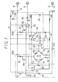
- a bridge circuit 100 (sensor means) is constructed, as indicated in FIG. 1. It is so designed that the resistance values of the strain gages located at one diagonal position of the strain gage bridge circuit are increased in response to a pressure increase, whereas the resistance values of the strain gages located at the other diagonal position thereof are decreased in response to a pressure increase.
- the bridge circuit may be constituted by employing two sets of strain gages in such a manner that these strain gages are provided at the respective bridge sides, and other bridge elements are fixed resistors, or one strain gage and a fixed resister. Variable resistors 15 and 16 are employed so as to correct an unbalance voltage of the bridge circuit 100.
- a constant current is supplied from a constant current circuit 200 constructed of resistors 17 to 20 and an operational amplifier 29 and so on to this bridge circuit 100.
- a constant current is furnished to the bridge circuit 100, which is produced by dividing a voltage difference between a power supply voltage and a reference voltage by a resistance value of a resistor 19.
- This reference voltage is derived by subdividing the power supply voltage by resistors 17 and 18.
- the bridge circuit 100 Upon receipt of this constant current, the bridge circuit 100 outputs voltages V1 and V2 in response to the pressure applied to the diaphragm 5b.
- This amplifier circuit 300 is constructed of operational amplifiers 30 to 32, transistors 33, 34, and resistors 21 and 25 etc.
- the voltage V1 from the bridge circuit 100 is applied to a non-invert input terminal of the operational amplifier 31, whereas the voltage V2 from the bridge circuit 100 is applied via the operational amplifier 30 and the resistor 21, which may function as a buffer, to an invert input terminal thereof.
- Both of these input voltages are differentially amplified by the operational amplifier 31, and then the transistors 33 and 34 are controlled based upon the output signal derived from this operational amplifier. With this operation, the output voltage (V1 - V2) of this bridge circuit 100 is converted into a current output.
- the current-converted current output is amplified by an amplifier circuit constructed of the operational amplifier 32 and the like, and a pressure detection signal is outputted to the output line O.
- resistors 26 to 28 are employed. It should be noted that the variable resistors 15 and 16 and so on are employed so as to obtain a desired output, and are adjusted when the semiconductor pressure sensor is manufactured.
- a different point of this sensor apparatus from the conventional sensor apparatus is as follows. That is, (1) capacitors 35, 46, 37 are employed with all resistors 17, 19, 22 directly connected to the power supply line V in the constant current circuit 200 and the amplifier circuit 300, and then the filter circuit is constituted together with the resistors 17, 19, 22. (2) The power supply voltage to the operational amplifiers 29 to 32 is applied from another power supply line V' different from the above-explained power supply line V, and such a filter circuit arranged by the resistor 40 and the capacitor 39 are provided in this power supply line V'. (3) A filter circuit arranged by the resistor 25 and the capacitor 38 is provided in the output line O from the operational amplifier 32.
- capacitors 35 to 39 are manufactured as, for instance, an MOS capacitor, or a junction capacitor, fabricated in the normal IC, in the integrated sensor chip 5 similar to other circuit elements.
- One of these capacitors, namely capacitor 35 is illustrated in FIG. 3.
- Such a filter circuit arranged by the resistor and the capacitor is employed and for the RF noise measure.
- various ideas have been proposed.
- the filter circuit is namely provided on the power supply line, as disclosed in Japanese Laid-open Patent Application No. 58-11242.
- the filter circuit is formed in the power supply line, the voltages supplied to the various circuits are lowered by the voltage drop caused by the resistor for constituting this filter circuit. Then, when the sensor apparatus of the present invention is employed, such a voltage drop gives unwanted effects to the sensor operations.
- the filter circuit is not merely formed in the power supply line V for driving the sensor apparatus and having the sensor characteristic, but the filter circuit is arranged in the pressure detecting circuit unit by utilizing the conventionally employed resistors 17, 19, 22. With employment such an arrangement, the RF (high frequency) noise measure can be achieved without giving adverse influences to the sensor characteristic.
- another power supply line V' separated from the above-descried power supply line V namely the power supply line for driving the operational amplifier irrelevant to the sensor characteristic is branched from the branching point A.
- the power is supplied via this power supply line V' to the operational amplifiers 29 to 32, and also the filter circuit arranged by the resistor 40 and the capacitor 39 is formed on this power supply line V' in order to achieve the RF noise measure, with respect to the power supplies to the operational amplifiers 29 to 32.
- the above-explained filter circuit corresponds to a low-pass filter for performing a noise elimination.
- a similar idea may also be applied to the resistors 19 and 22 other then the resistor 17, and thus the capacitors 36 and 37 are employed so as to obtain a desired filter characteristic.
- the resistor for constructing the filter circuit is directly connected to the power supply line V and is known which is required to carry out the pressure detecting operation in the pressure detecting circuit unit. That is, the resistor 17 corresponds to such a resistor used to produce the reference voltage for determining the value of the constant current in the constant current circuit 200, the resistor 19 corresponds to such a resistor for determining the value of this constant current in relation with the reference voltage and the power supply voltage, and the resistor 22 corresponds to a resistor used to define the operation point of the amplifier circuit 300.
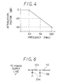
- the resistance value of the resistor 40 cannot be selected to be a large value due to a relationship between the consumed current and the allowable voltage drop. Considering these conditions, when the resistance value of the resistor 40 is selected to the 700 ⁇ , if the capacitance of the capacitor 39 is 40 pF, the cut-off frequency becomes approximately 5.7 MHz, which may provide a similar filter characteristic to that of FIG. 4.
- FIG. 5 graphically represents measurement results in electric field strengths E at which the erroneous operation is performed in the EMC level (high frequency: 1 MHz to 1,000 MHz) when the immunity test by the TEM cell (transverse electro-magnetic cell) apparatus.
- a waveform "a” indicated by a solid line shows measurement results obtained by the semiconductor pressure sensor according to this embodiment, shown in FIG. 1.
- Another waveform "b” indicated by a broken line shows measurement results by the semiconductor pressure sensor, as a comparison example, in the case that the capacitors 35, 36, 37, 38, 39 and the resistors 25, 40 of FIG. 1 are not connected.
- the RF noise withstanding amounts of both operational amplifiers 29 to 32 are essentially identical to each other.
- the Applicant has proposed the semiconductor apparatus with the anti-EMI measure (Japanese Laid-open Patent Application No. 5-327264).
- the capacitors are connected between the non-inventing terminals of the operational amplifiers 31, 30 and the ground, whereas the capacitors 38, 39 and the resistors 24, 25, 40 are not connected to the circuit arrangement of FIG. 1 in this embodiment.
- the Inventors could confirm by carrying out the immunity test by the same TEM cell apparatus as in FIG. 5 for the circuit arrangement disclosed in this prior application that the RF noise withstanding amount could not be expected as in the waveform "a" of this embodiment, but may be similar to the waveform "b".
- the circuit arrangement of which is constituted as follows: In the power supply line V defined from the branch point A between the power supply line V and the power supply line V' toward the sensor circuit units 100, 200 and 300, the filter circuit arranged by the resistor 17 and the capacitor 35, the filter circuit arranged by the resistor 19 and the capacitor 36, and the filter circuit arranged by the resistor 22 and the capacitor 37 are provided. Also, the filter circuit formed by the resistor 40 and the capacitor 39 is provided in the power supply line V', and the filter circuit formed by the resistor 25 and the capacitor 38 is provided in the output line O.
- the filter circuit constituted in the power supply line V among the respective filter circuits employed as the RF noise measure is realized by utilizing the resistors 17, 19, 22 directly connected to the power supply lie V and by providing the capacitors 35, 36, 37 in these resistors. This has been arranged by taking account of deterioration in the sensor characteristic caused by the voltage drops in the resistors for constituting the filter circuit and by lowering the supply voltages to the respective circuits.
- the present invention is not limited to this filter circuit arrangement.
- the filter circuit may be constituted by newly employing a resistor and a capacitor, which are connected to such a power supply line V defined from the branch point A between the power supply line V and the power supply line V' to the pressure detecting circuit unit.
- the circuit constant of the resistor in the filter circuit may be designed to be an optimum value in combination of the circuit constants of the resistors 17, 19, 22.
- the RF noise measure can be achieved without utilizing the resistors directly connected to the power supply line V.
- the filter circuit is constituted on the power supply terminal side from the branch point A between the power supply line V and the power supply line V', even if the sensor characteristic (circuit constant of resistor) is considered, the voltage drop is produced by the current of the operational amplifier power supply, which flows through the resistor of this filter circuit. Accordingly, the performance deterioration caused by the low sensor output could not be avoided. Therefore, it is not preferable to employ the filter circuit between the branch point A and the power supply terminal.
- the circuits required as the RF noise measure for the sensor apparatus may be achieved as follows:
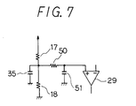
- another filter circuit constructed of a resistor 50 having a high resistance value and a capacitor 51 is additionally provided with the filter circuit constructed of the resistor 17 and the capacitor 35, so that a multi-staged filter circuit may be obtained.
- the resistance value of the resistor 50 is large, the capacitance value of the capacitor 51 may be small.
- the forming area thereof may be made small, resulting in an integrated form in the sensor chip.
- the present invention may be applied to such various sensor apparatus as an acceleration sensor, a magnetic sensor, and an optical sensor.
Landscapes
- Physics & Mathematics (AREA)
- General Physics & Mathematics (AREA)
- Measuring Fluid Pressure (AREA)
- Indication And Recording Devices For Special Purposes And Tariff Metering Devices (AREA)
Applications Claiming Priority (6)
| Application Number | Priority Date | Filing Date | Title |
|---|---|---|---|
| JP27083694 | 1994-11-04 | ||
| JP270836/94 | 1994-11-04 | ||
| JP27083694 | 1994-11-04 | ||
| JP265342/95 | 1995-10-13 | ||
| JP26534295A JP3427594B2 (ja) | 1994-11-04 | 1995-10-13 | センサ装置 |
| JP26534295 | 1995-10-13 |
Publications (3)
| Publication Number | Publication Date |
|---|---|
| EP0710825A2 EP0710825A2 (en) | 1996-05-08 |
| EP0710825A3 EP0710825A3 (enExample) | 1996-06-12 |
| EP0710825B1 true EP0710825B1 (en) | 2000-06-14 |
Family
ID=26546938
Family Applications (1)
| Application Number | Title | Priority Date | Filing Date |
|---|---|---|---|
| EP95117338A Expired - Lifetime EP0710825B1 (en) | 1994-11-04 | 1995-11-03 | A sensor circuit capable of preventing high frequency noise |
Country Status (4)
| Country | Link |
|---|---|
| US (1) | US5684428A (enExample) |
| EP (1) | EP0710825B1 (enExample) |
| JP (1) | JP3427594B2 (enExample) |
| DE (1) | DE69517488T2 (enExample) |
Families Citing this family (11)
| Publication number | Priority date | Publication date | Assignee | Title |
|---|---|---|---|---|
| JP3278363B2 (ja) * | 1996-11-18 | 2002-04-30 | 三菱電機株式会社 | 半導体加速度センサ |
| JPH10281897A (ja) * | 1997-04-08 | 1998-10-23 | Mitsubishi Electric Corp | 半導体圧力検出装置 |
| DE502006007335D1 (de) * | 2006-11-11 | 2010-08-12 | Mettler Toledo Ag | Verfahren zur Überwachung und/oder Bestimmung des Zustandes einer Kraftmessvorrichtung und Kraftmessvorrichtung |
| FR2910958B1 (fr) | 2006-12-28 | 2009-02-20 | Siemens Vdo Automotive Sas | Capteur integre a rejection de couplage capacitif a la masse mecanique |
| WO2011086617A1 (ja) * | 2010-01-13 | 2011-07-21 | パナソニック株式会社 | 高周波ノイズ除去機能付き増幅器、マイクロフォンモジュール及びセンサモジュール |
| US8878598B2 (en) * | 2010-12-28 | 2014-11-04 | British Virgin Islands Central Digital Inc. | Sensing module |
| JP5867688B2 (ja) * | 2011-09-22 | 2016-02-24 | 国立大学法人 東京大学 | 触覚センサ及び多軸触覚センサ |
| JP5935333B2 (ja) * | 2012-01-13 | 2016-06-15 | 株式会社デンソー | 半導体センサ |
| JP5923742B2 (ja) * | 2012-04-20 | 2016-05-25 | パナソニックIpマネジメント株式会社 | Ic周辺回路 |
| JP6365158B2 (ja) * | 2014-09-12 | 2018-08-01 | 株式会社デンソー | 筒内圧検出装置 |
| JP6500690B2 (ja) * | 2015-08-11 | 2019-04-17 | 富士電機株式会社 | 半導体物理量センサ装置 |
Family Cites Families (10)
| Publication number | Priority date | Publication date | Assignee | Title |
|---|---|---|---|---|
| JPS55155253A (en) | 1979-05-22 | 1980-12-03 | Nippon Denso Co Ltd | Output compensation circuit for bridge type measuring apparatus |
| JPS57169644A (en) | 1981-04-14 | 1982-10-19 | Nippon Denso Co Ltd | Semiconductor type pressure sensor |
| JPS6043507B2 (ja) | 1981-07-14 | 1985-09-28 | 大成建設株式会社 | 鋼構造筋違架構 |
| JPS58112424A (ja) * | 1981-12-25 | 1983-07-04 | 日本電気株式会社 | 電源雑音抑圧方式 |
| JPS6063685A (ja) * | 1983-09-16 | 1985-04-12 | Nec Corp | 座標入力装置用雑音除去回路 |
| JP2609137B2 (ja) * | 1988-09-02 | 1997-05-14 | 藤森工業株式会社 | 液晶表示パネル用電極基板製造用の反応性耐透気性ポリマーおよびそれを用いた液晶表示パネル用電極基板 |
| JP2730152B2 (ja) | 1989-03-15 | 1998-03-25 | 株式会社デンソー | 圧力・温度複合検出装置 |
| GB2257787B (en) * | 1991-07-03 | 1994-08-03 | Motorola Inc | Sensor signal conditioning circuit |
| JPH05153782A (ja) * | 1991-11-26 | 1993-06-18 | Fuji Electric Co Ltd | ノイズ防止装置 |
| JP3568546B2 (ja) | 1992-05-25 | 2004-09-22 | 株式会社デンソー | 半導体装置 |
-
1995
- 1995-10-13 JP JP26534295A patent/JP3427594B2/ja not_active Expired - Fee Related
- 1995-11-03 EP EP95117338A patent/EP0710825B1/en not_active Expired - Lifetime
- 1995-11-03 US US08/552,789 patent/US5684428A/en not_active Expired - Lifetime
- 1995-11-03 DE DE69517488T patent/DE69517488T2/de not_active Expired - Lifetime
Also Published As
| Publication number | Publication date |
|---|---|
| DE69517488D1 (de) | 2000-07-20 |
| JPH08184462A (ja) | 1996-07-16 |
| US5684428A (en) | 1997-11-04 |
| EP0710825A3 (enExample) | 1996-06-12 |
| DE69517488T2 (de) | 2001-02-08 |
| JP3427594B2 (ja) | 2003-07-22 |
| EP0710825A2 (en) | 1996-05-08 |
Similar Documents
| Publication | Publication Date | Title |
|---|---|---|
| EP0710825B1 (en) | A sensor circuit capable of preventing high frequency noise | |
| CA1258499A (en) | Intermediate frequency amplification circuit capable of detecting a field strength with low electric power | |
| US5107210A (en) | Displacement sensing circuit with coil and band pass filter for attenuating external interference | |
| US4403183A (en) | Active voltage probe | |
| EP1156583B1 (en) | Amplification circuit for electric charge type sensor | |
| US4484146A (en) | Differential amplifier containing a low-pass filter | |
| US4626678A (en) | Light detecting circuit | |
| US5625320A (en) | Differential preamplifier and pre-emphasis network | |
| US20100109647A1 (en) | Physical quantity sensing apparatus having an internal circuit, a filter circuit having resistors, power supply, grounding, and output pads, with the length and width of wiring between the output or power supply pad and the internal circuit set so that the resistance of resistors and the parasitic resistance component of the wiring satisfy a certain relational expression | |
| EP1424562A1 (en) | Sensor capacity sensing apparatus and sensor capacity sensing method | |
| US5789797A (en) | Semiconductor device that suppresses electromagnetic noise | |
| US5854421A (en) | Semiconductor sensors and method for adjusting the output | |
| US6718816B2 (en) | Monolithic I.C. implemented calibration circuit | |
| KR20010006034A (ko) | 임피던스-전압 변환기 및 변환방법 | |
| CN219456209U (zh) | 电容式mems加速度计 | |
| US7436052B2 (en) | Repatterned integrated circuit chip package | |
| JP2002090243A (ja) | 圧力センサ用電子回路 | |
| KR20040041159A (ko) | 전위 고정 장치 및 전위 고정 방법 | |
| JPH07286924A (ja) | センサ装置 | |
| US11333686B2 (en) | Non-directional in-line suspended PCB power sensing coupler | |
| JPS63193027A (ja) | 圧電型圧力検出装置 | |
| JPH02150732A (ja) | 圧力変換器の補償回路 | |
| US7005895B2 (en) | Driver circuit with frequency-dependent signal feedback | |
| Yu et al. | Eddy current microsensor for use in micromachine applications | |
| JPH0954112A (ja) | 加速度センサ装置 |
Legal Events
| Date | Code | Title | Description |
|---|---|---|---|
| PUAI | Public reference made under article 153(3) epc to a published international application that has entered the european phase |
Free format text: ORIGINAL CODE: 0009012 |
|
| PUAL | Search report despatched |
Free format text: ORIGINAL CODE: 0009013 |
|
| AK | Designated contracting states |
Kind code of ref document: A2 Designated state(s): DE FR GB IT |
|
| AK | Designated contracting states |
Kind code of ref document: A3 Designated state(s): DE FR GB IT |
|
| 17P | Request for examination filed |
Effective date: 19960605 |
|
| RAP1 | Party data changed (applicant data changed or rights of an application transferred) |
Owner name: DENSO CORPORATION |
|
| 17Q | First examination report despatched |
Effective date: 19981022 |
|
| GRAG | Despatch of communication of intention to grant |
Free format text: ORIGINAL CODE: EPIDOS AGRA |
|
| GRAG | Despatch of communication of intention to grant |
Free format text: ORIGINAL CODE: EPIDOS AGRA |
|
| GRAH | Despatch of communication of intention to grant a patent |
Free format text: ORIGINAL CODE: EPIDOS IGRA |
|
| GRAH | Despatch of communication of intention to grant a patent |
Free format text: ORIGINAL CODE: EPIDOS IGRA |
|
| GRAA | (expected) grant |
Free format text: ORIGINAL CODE: 0009210 |
|
| AK | Designated contracting states |
Kind code of ref document: B1 Designated state(s): DE FR GB IT |
|
| REF | Corresponds to: |
Ref document number: 69517488 Country of ref document: DE Date of ref document: 20000720 |
|
| ITF | It: translation for a ep patent filed | ||
| ET | Fr: translation filed | ||
| PLBE | No opposition filed within time limit |
Free format text: ORIGINAL CODE: 0009261 |
|
| STAA | Information on the status of an ep patent application or granted ep patent |
Free format text: STATUS: NO OPPOSITION FILED WITHIN TIME LIMIT |
|
| 26N | No opposition filed | ||
| REG | Reference to a national code |
Ref country code: GB Ref legal event code: IF02 |
|
| PGFP | Annual fee paid to national office [announced via postgrant information from national office to epo] |
Ref country code: GB Payment date: 20131120 Year of fee payment: 19 Ref country code: DE Payment date: 20131121 Year of fee payment: 19 Ref country code: FR Payment date: 20131120 Year of fee payment: 19 |
|
| PGFP | Annual fee paid to national office [announced via postgrant information from national office to epo] |
Ref country code: IT Payment date: 20131128 Year of fee payment: 19 |
|
| REG | Reference to a national code |
Ref country code: DE Ref legal event code: R119 Ref document number: 69517488 Country of ref document: DE |
|
| GBPC | Gb: european patent ceased through non-payment of renewal fee |
Effective date: 20141103 |
|
| REG | Reference to a national code |
Ref country code: FR Ref legal event code: ST Effective date: 20150731 |
|
| PG25 | Lapsed in a contracting state [announced via postgrant information from national office to epo] |
Ref country code: DE Free format text: LAPSE BECAUSE OF NON-PAYMENT OF DUE FEES Effective date: 20150602 Ref country code: GB Free format text: LAPSE BECAUSE OF NON-PAYMENT OF DUE FEES Effective date: 20141103 |
|
| PG25 | Lapsed in a contracting state [announced via postgrant information from national office to epo] |
Ref country code: FR Free format text: LAPSE BECAUSE OF NON-PAYMENT OF DUE FEES Effective date: 20141201 |
|
| PG25 | Lapsed in a contracting state [announced via postgrant information from national office to epo] |
Ref country code: IT Free format text: LAPSE BECAUSE OF NON-PAYMENT OF DUE FEES Effective date: 20141103 |