EP0709836A2 - Procédé pour accéder à un milieu d'enregistrement, appareil et procédé pour traiter l'information - Google Patents
Procédé pour accéder à un milieu d'enregistrement, appareil et procédé pour traiter l'information Download PDFInfo
- Publication number
- EP0709836A2 EP0709836A2 EP95203410A EP95203410A EP0709836A2 EP 0709836 A2 EP0709836 A2 EP 0709836A2 EP 95203410 A EP95203410 A EP 95203410A EP 95203410 A EP95203410 A EP 95203410A EP 0709836 A2 EP0709836 A2 EP 0709836A2
- Authority
- EP
- European Patent Office
- Prior art keywords
- recording medium
- recording
- probe electrode
- edge portion
- information
- Prior art date
- Legal status (The legal status is an assumption and is not a legal conclusion. Google has not performed a legal analysis and makes no representation as to the accuracy of the status listed.)
- Granted
Links
- 238000000034 method Methods 0.000 title claims abstract description 72
- 238000012545 processing Methods 0.000 title claims abstract description 14
- 239000000523 sample Substances 0.000 claims abstract description 119
- 230000010365 information processing Effects 0.000 claims description 9
- 239000000758 substrate Substances 0.000 description 27
- 239000010408 film Substances 0.000 description 13
- 239000000463 material Substances 0.000 description 13
- 230000015572 biosynthetic process Effects 0.000 description 10
- 239000004642 Polyimide Substances 0.000 description 7
- 238000004519 manufacturing process Methods 0.000 description 7
- 229920001721 polyimide Polymers 0.000 description 7
- 230000008569 process Effects 0.000 description 7
- 239000013078 crystal Substances 0.000 description 6
- 230000000694 effects Effects 0.000 description 6
- NLKNQRATVPKPDG-UHFFFAOYSA-M potassium iodide Chemical compound [K+].[I-] NLKNQRATVPKPDG-UHFFFAOYSA-M 0.000 description 6
- 238000005530 etching Methods 0.000 description 5
- 229910052737 gold Inorganic materials 0.000 description 5
- 239000010931 gold Substances 0.000 description 5
- 239000000243 solution Substances 0.000 description 5
- 238000000151 deposition Methods 0.000 description 4
- 230000008021 deposition Effects 0.000 description 4
- PCHJSUWPFVWCPO-UHFFFAOYSA-N gold Chemical compound [Au] PCHJSUWPFVWCPO-UHFFFAOYSA-N 0.000 description 4
- 239000010445 mica Substances 0.000 description 4
- 229910052618 mica group Inorganic materials 0.000 description 4
- 239000010409 thin film Substances 0.000 description 4
- 238000007740 vapor deposition Methods 0.000 description 4
- XLYOFNOQVPJJNP-UHFFFAOYSA-N water Substances O XLYOFNOQVPJJNP-UHFFFAOYSA-N 0.000 description 4
- 239000003638 chemical reducing agent Substances 0.000 description 3
- 238000001514 detection method Methods 0.000 description 3
- 238000003708 edge detection Methods 0.000 description 3
- 238000010894 electron beam technology Methods 0.000 description 3
- 238000010884 ion-beam technique Methods 0.000 description 3
- 150000002500 ions Chemical class 0.000 description 3
- 239000003550 marker Substances 0.000 description 3
- 229910052751 metal Inorganic materials 0.000 description 3
- 239000002184 metal Substances 0.000 description 3
- 238000000206 photolithography Methods 0.000 description 3
- 229920005575 poly(amic acid) Polymers 0.000 description 3
- REYJJPSVUYRZGE-UHFFFAOYSA-N Octadecylamine Chemical class CCCCCCCCCCCCCCCCCCN REYJJPSVUYRZGE-UHFFFAOYSA-N 0.000 description 2
- XUIMIQQOPSSXEZ-UHFFFAOYSA-N Silicon Chemical compound [Si] XUIMIQQOPSSXEZ-UHFFFAOYSA-N 0.000 description 2
- 230000008859 change Effects 0.000 description 2
- 238000003776 cleavage reaction Methods 0.000 description 2
- 150000001875 compounds Chemical class 0.000 description 2
- 238000002347 injection Methods 0.000 description 2
- 239000007924 injection Substances 0.000 description 2
- 230000007246 mechanism Effects 0.000 description 2
- 238000000386 microscopy Methods 0.000 description 2
- 150000002894 organic compounds Chemical class 0.000 description 2
- 238000002360 preparation method Methods 0.000 description 2
- 238000003672 processing method Methods 0.000 description 2
- 230000004044 response Effects 0.000 description 2
- 230000007017 scission Effects 0.000 description 2
- 239000004065 semiconductor Substances 0.000 description 2
- 229910052710 silicon Inorganic materials 0.000 description 2
- 239000010703 silicon Substances 0.000 description 2
- 239000002904 solvent Substances 0.000 description 2
- 239000000126 substance Substances 0.000 description 2
- 239000004925 Acrylic resin Substances 0.000 description 1
- 229920000178 Acrylic resin Polymers 0.000 description 1
- -1 HOPG Substances 0.000 description 1
- FXHOOIRPVKKKFG-UHFFFAOYSA-N N,N-Dimethylacetamide Chemical compound CN(C)C(C)=O FXHOOIRPVKKKFG-UHFFFAOYSA-N 0.000 description 1
- 239000004696 Poly ether ether ketone Substances 0.000 description 1
- 229910021417 amorphous silicon Inorganic materials 0.000 description 1
- 238000013459 approach Methods 0.000 description 1
- 239000008346 aqueous phase Substances 0.000 description 1
- 230000002238 attenuated effect Effects 0.000 description 1
- JUPQTSLXMOCDHR-UHFFFAOYSA-N benzene-1,4-diol;bis(4-fluorophenyl)methanone Chemical compound OC1=CC=C(O)C=C1.C1=CC(F)=CC=C1C(=O)C1=CC=C(F)C=C1 JUPQTSLXMOCDHR-UHFFFAOYSA-N 0.000 description 1
- QHIWVLPBUQWDMQ-UHFFFAOYSA-N butyl prop-2-enoate;methyl 2-methylprop-2-enoate;prop-2-enoic acid Chemical compound OC(=O)C=C.COC(=O)C(C)=C.CCCCOC(=O)C=C QHIWVLPBUQWDMQ-UHFFFAOYSA-N 0.000 description 1
- 239000004020 conductor Substances 0.000 description 1
- 229910052802 copper Inorganic materials 0.000 description 1
- 238000012937 correction Methods 0.000 description 1
- 230000006378 damage Effects 0.000 description 1
- 230000007423 decrease Effects 0.000 description 1
- 230000007547 defect Effects 0.000 description 1
- 238000013461 design Methods 0.000 description 1
- 238000011161 development Methods 0.000 description 1
- NAPSCFZYZVSQHF-UHFFFAOYSA-N dimantine Chemical compound CCCCCCCCCCCCCCCCCCN(C)C NAPSCFZYZVSQHF-UHFFFAOYSA-N 0.000 description 1
- 230000008020 evaporation Effects 0.000 description 1
- 238000001704 evaporation Methods 0.000 description 1
- 230000006870 function Effects 0.000 description 1
- 239000011521 glass Substances 0.000 description 1
- 239000010439 graphite Substances 0.000 description 1
- 229910002804 graphite Inorganic materials 0.000 description 1
- 238000010438 heat treatment Methods 0.000 description 1
- 150000003949 imides Chemical class 0.000 description 1
- 238000007654 immersion Methods 0.000 description 1
- 238000009434 installation Methods 0.000 description 1
- 238000005468 ion implantation Methods 0.000 description 1
- 230000001788 irregular Effects 0.000 description 1
- 238000005259 measurement Methods 0.000 description 1
- 239000002609 medium Substances 0.000 description 1
- 230000003446 memory effect Effects 0.000 description 1
- 150000002739 metals Chemical class 0.000 description 1
- 238000002156 mixing Methods 0.000 description 1
- 229910052750 molybdenum Inorganic materials 0.000 description 1
- 238000012544 monitoring process Methods 0.000 description 1
- 239000000178 monomer Substances 0.000 description 1
- 229920001778 nylon Polymers 0.000 description 1
- 230000003287 optical effect Effects 0.000 description 1
- 239000012860 organic pigment Substances 0.000 description 1
- 230000010355 oscillation Effects 0.000 description 1
- 239000002245 particle Substances 0.000 description 1
- 229910052697 platinum Inorganic materials 0.000 description 1
- 229920005668 polycarbonate resin Polymers 0.000 description 1
- 239000004431 polycarbonate resin Substances 0.000 description 1
- 229920002530 polyetherether ketone Polymers 0.000 description 1
- 229920000139 polyethylene terephthalate Polymers 0.000 description 1
- 239000005020 polyethylene terephthalate Substances 0.000 description 1
- 239000010453 quartz Substances 0.000 description 1
- 238000005070 sampling Methods 0.000 description 1
- 229910052594 sapphire Inorganic materials 0.000 description 1
- 239000010980 sapphire Substances 0.000 description 1
- 230000035945 sensitivity Effects 0.000 description 1
- VYPSYNLAJGMNEJ-UHFFFAOYSA-N silicon dioxide Inorganic materials O=[Si]=O VYPSYNLAJGMNEJ-UHFFFAOYSA-N 0.000 description 1
- 229910052709 silver Inorganic materials 0.000 description 1
- 239000007787 solid Substances 0.000 description 1
- 238000001771 vacuum deposition Methods 0.000 description 1
- 235000012431 wafers Nutrition 0.000 description 1
Images


Classifications
-
- G—PHYSICS
- G11—INFORMATION STORAGE
- G11B—INFORMATION STORAGE BASED ON RELATIVE MOVEMENT BETWEEN RECORD CARRIER AND TRANSDUCER
- G11B19/00—Driving, starting, stopping record carriers not specifically of filamentary or web form, or of supports therefor; Control thereof; Control of operating function ; Driving both disc and head
- G11B19/20—Driving; Starting; Stopping; Control thereof
-
- B—PERFORMING OPERATIONS; TRANSPORTING
- B82—NANOTECHNOLOGY
- B82Y—SPECIFIC USES OR APPLICATIONS OF NANOSTRUCTURES; MEASUREMENT OR ANALYSIS OF NANOSTRUCTURES; MANUFACTURE OR TREATMENT OF NANOSTRUCTURES
- B82Y10/00—Nanotechnology for information processing, storage or transmission, e.g. quantum computing or single electron logic
-
- G—PHYSICS
- G11—INFORMATION STORAGE
- G11B—INFORMATION STORAGE BASED ON RELATIVE MOVEMENT BETWEEN RECORD CARRIER AND TRANSDUCER
- G11B17/00—Guiding record carriers not specifically of filamentary or web form, or of supports therefor
- G11B17/34—Guiding record carriers during transducing operation, e.g. for track following
-
- G—PHYSICS
- G11—INFORMATION STORAGE
- G11B—INFORMATION STORAGE BASED ON RELATIVE MOVEMENT BETWEEN RECORD CARRIER AND TRANSDUCER
- G11B23/00—Record carriers not specific to the method of recording or reproducing; Accessories, e.g. containers, specially adapted for co-operation with the recording or reproducing apparatus ; Intermediate mediums; Apparatus or processes specially adapted for their manufacture
- G11B23/0014—Record carriers not specific to the method of recording or reproducing; Accessories, e.g. containers, specially adapted for co-operation with the recording or reproducing apparatus ; Intermediate mediums; Apparatus or processes specially adapted for their manufacture record carriers not specifically of filamentary or web form
-
- G—PHYSICS
- G11—INFORMATION STORAGE
- G11B—INFORMATION STORAGE BASED ON RELATIVE MOVEMENT BETWEEN RECORD CARRIER AND TRANSDUCER
- G11B9/00—Recording or reproducing using a method not covered by one of the main groups G11B3/00 - G11B7/00; Record carriers therefor
- G11B9/12—Recording or reproducing using a method not covered by one of the main groups G11B3/00 - G11B7/00; Record carriers therefor using near-field interactions; Record carriers therefor
- G11B9/14—Recording or reproducing using a method not covered by one of the main groups G11B3/00 - G11B7/00; Record carriers therefor using near-field interactions; Record carriers therefor using microscopic probe means, i.e. recording or reproducing by means directly associated with the tip of a microscopic electrical probe as used in Scanning Tunneling Microscopy [STM] or Atomic Force Microscopy [AFM] for inducing physical or electrical perturbations in a recording medium; Record carriers or media specially adapted for such transducing of information
- G11B9/1418—Disposition or mounting of heads or record carriers
- G11B9/1427—Disposition or mounting of heads or record carriers with provision for moving the heads or record carriers relatively to each other or for access to indexed parts without effectively imparting a relative movement
- G11B9/1436—Disposition or mounting of heads or record carriers with provision for moving the heads or record carriers relatively to each other or for access to indexed parts without effectively imparting a relative movement with provision for moving the heads or record carriers relatively to each other
- G11B9/1454—Positioning the head or record carrier into or out of operative position or across information tracks; Alignment of the head relative to the surface of the record carrier
-
- G—PHYSICS
- G11—INFORMATION STORAGE
- G11B—INFORMATION STORAGE BASED ON RELATIVE MOVEMENT BETWEEN RECORD CARRIER AND TRANSDUCER
- G11B9/00—Recording or reproducing using a method not covered by one of the main groups G11B3/00 - G11B7/00; Record carriers therefor
- G11B9/12—Recording or reproducing using a method not covered by one of the main groups G11B3/00 - G11B7/00; Record carriers therefor using near-field interactions; Record carriers therefor
- G11B9/14—Recording or reproducing using a method not covered by one of the main groups G11B3/00 - G11B7/00; Record carriers therefor using near-field interactions; Record carriers therefor using microscopic probe means, i.e. recording or reproducing by means directly associated with the tip of a microscopic electrical probe as used in Scanning Tunneling Microscopy [STM] or Atomic Force Microscopy [AFM] for inducing physical or electrical perturbations in a recording medium; Record carriers or media specially adapted for such transducing of information
- G11B9/1463—Record carriers for recording or reproduction involving the use of microscopic probe means
- G11B9/1472—Record carriers for recording or reproduction involving the use of microscopic probe means characterised by the form
- G11B9/1481—Auxiliary features, e.g. reference or indexing surfaces
-
- Y—GENERAL TAGGING OF NEW TECHNOLOGICAL DEVELOPMENTS; GENERAL TAGGING OF CROSS-SECTIONAL TECHNOLOGIES SPANNING OVER SEVERAL SECTIONS OF THE IPC; TECHNICAL SUBJECTS COVERED BY FORMER USPC CROSS-REFERENCE ART COLLECTIONS [XRACs] AND DIGESTS
- Y10—TECHNICAL SUBJECTS COVERED BY FORMER USPC
- Y10S—TECHNICAL SUBJECTS COVERED BY FORMER USPC CROSS-REFERENCE ART COLLECTIONS [XRACs] AND DIGESTS
- Y10S977/00—Nanotechnology
- Y10S977/84—Manufacture, treatment, or detection of nanostructure
- Y10S977/849—Manufacture, treatment, or detection of nanostructure with scanning probe
-
- Y—GENERAL TAGGING OF NEW TECHNOLOGICAL DEVELOPMENTS; GENERAL TAGGING OF CROSS-SECTIONAL TECHNOLOGIES SPANNING OVER SEVERAL SECTIONS OF THE IPC; TECHNICAL SUBJECTS COVERED BY FORMER USPC CROSS-REFERENCE ART COLLECTIONS [XRACs] AND DIGESTS
- Y10—TECHNICAL SUBJECTS COVERED BY FORMER USPC
- Y10S—TECHNICAL SUBJECTS COVERED BY FORMER USPC CROSS-REFERENCE ART COLLECTIONS [XRACs] AND DIGESTS
- Y10S977/00—Nanotechnology
- Y10S977/84—Manufacture, treatment, or detection of nanostructure
- Y10S977/88—Manufacture, treatment, or detection of nanostructure with arrangement, process, or apparatus for testing
- Y10S977/881—Microscopy or spectroscopy, e.g. sem, tem
-
- Y—GENERAL TAGGING OF NEW TECHNOLOGICAL DEVELOPMENTS; GENERAL TAGGING OF CROSS-SECTIONAL TECHNOLOGIES SPANNING OVER SEVERAL SECTIONS OF THE IPC; TECHNICAL SUBJECTS COVERED BY FORMER USPC CROSS-REFERENCE ART COLLECTIONS [XRACs] AND DIGESTS
- Y10—TECHNICAL SUBJECTS COVERED BY FORMER USPC
- Y10S—TECHNICAL SUBJECTS COVERED BY FORMER USPC CROSS-REFERENCE ART COLLECTIONS [XRACs] AND DIGESTS
- Y10S977/00—Nanotechnology
- Y10S977/902—Specified use of nanostructure
- Y10S977/932—Specified use of nanostructure for electronic or optoelectronic application
- Y10S977/943—Information storage or retrieval using nanostructure
- Y10S977/947—Information storage or retrieval using nanostructure with scanning probe instrument
-
- Y—GENERAL TAGGING OF NEW TECHNOLOGICAL DEVELOPMENTS; GENERAL TAGGING OF CROSS-SECTIONAL TECHNOLOGIES SPANNING OVER SEVERAL SECTIONS OF THE IPC; TECHNICAL SUBJECTS COVERED BY FORMER USPC CROSS-REFERENCE ART COLLECTIONS [XRACs] AND DIGESTS
- Y10—TECHNICAL SUBJECTS COVERED BY FORMER USPC
- Y10S—TECHNICAL SUBJECTS COVERED BY FORMER USPC CROSS-REFERENCE ART COLLECTIONS [XRACs] AND DIGESTS
- Y10S977/00—Nanotechnology
- Y10S977/902—Specified use of nanostructure
- Y10S977/932—Specified use of nanostructure for electronic or optoelectronic application
- Y10S977/949—Radiation emitter using nanostructure
- Y10S977/95—Electromagnetic energy
- Y10S977/951—Laser
Definitions
- the present invention relates to a high-density recording medium, and a method of access thereto. More particularly, the present invention relates to a method of access to a recording-reproducing region in recording and reproduction of data by employing scanning tunnel microscopy (STM) for access and tracking with a probe.
- STM scanning tunnel microscopy
- the present invention further relates to an information-processing apparatus and an information-processing method which enable high-density recording and high-speed reproduction.
- memory materials are utilized in a variety of application fields such as computers and related apparatuses, video discs, digital audio discs, and so forth, and are the key materials in electronics industries. Therefore, the development of the memory materials is actively being made. Generally, memory materials are required to have the performances below depending on the uses:
- magnetic memory devices and semiconductor memory devices which employ a magnetic body or a semiconductor as the base material have been principally used for the memory systems.
- inexpensive and high-density recording mediums have come to be used which utilizes optical memory employing an organic thin film of an organic pigment, a photopolymer, or the like.
- STM scanning tunnel microscopy
- the STM utilizes the tunnel current which flows through a metallic probe (or a probe electrode) when the metallic probe is brought close to an electroconductive substance at a distance of about 1 nm.
- This current is extremely sensitive to the change of the above distance, so that various information on the entire electron cloud in a real space can be read by scanning with a probe so as to maintain the tunnel current constant.
- the resolution in the plane direction is approximately 0.1 nm.
- EP A0174860 discloses a recording-reproducing apparatus which allows writing by eliminating atom particles adsorbed on a surface of a medium by employing an electron beam or the like and allows reproduction of the data by employing STM.
- USP 4,575,822 discloses a method of recording by injecting electric charges into a dielectric layer formed on the surface of the medium by employing tunnel current flowing between the surface of the recording medium and a probe electrode, and a method of recording by physical or magnetic destruction of the surface of the recording medium by employing a laser beam, electron beam, a corpuscular beam, or the like.
- EP A0272935 discloses a recording-reproducing method in which recording and reproducing of information is conducted by employing STM on a material giving memory effect in switching characteristics of voltage or electric current as the recording medium, for example, a thin film layer of a ⁇ -electron type organic compound or a chalcogenoid compound. This method enables a large capacity of recording and reproduction of as dense as 1012 bits/cm2.
- Tracking methods for high density memory include:
- the recording data can be recorded two-dimensionally or areally and the recording density is exceedingly high owing to the high resolution characteristics of STM.
- the whole surface of the recording medium have to be scanned two-dimensionally to detect the reference position marker, which takes considerable time before the marker is detected.
- the groove formed is required to be in the size of 30 nm to meet the recording pit size of around 10 nm.
- One way to realize it is working with an ion beam.
- a super-precise stage has to be employed which works with mechanical accuracy of 3 to 6 nm.
- Such an apparatus is of an exceedingly large size and requires restricted operating environment, being unsuitable for memory mediums which are to be mass-produced at low cost.
- the groove may be formed by working with an electron beam or by X-ray exposure, the width of the groove formed cannot be made smaller than approximately 0.3 ⁇ m, which makes impossible the high-density recording by utilizing the high resolution of STM.
- the high resolution of STM can be well utilized.
- a crystalline substrate cannot readily be obtained which has a complete lattice arrangement in stripe without disorder or defect throughout the required recording area of such as 1 cm2 corresponding to a recording density of 10 nm/bit and a recording capacity of 1012 bits. Therefore this method cannot satisfy the requirements of low cost and high productivity for the recording medium.
- the control mechanism may be simple for a recording-reproducing apparatus.
- the provision of such an electrode and a terminal for injecting tracking signals of two or three kinds in the medium results in extremely low recording density and makes the preparation process of recording mediums complicated, which lowers the productivity and the yield of the medium, preventing supply of the mediums at low cost.
- An object of the present invention is to provide a method of access for a recording medium, which is free from the above-mentioned disadvantages, realizes high-density of recording-reproducing by utilizing the characteristics of STM, and enables high-speed access to recorded position with a recording medium of low price and high productivity.
- Another object of the present invention is to provide an information-processing apparatus and an information-processing method which enable high-density recording and high-speed reproduction.
- a method of access of a probe electrode to a recording medium having on the surface thereof an edge portion having a level difference larger than a recording recess-projection or having an electron state different from a recording electron state comprising steps of detecting the edge portion; causing the probe electrode to scan at a certain angle to the edge portion; and moving the recording medium to a direction along the edge portion.
- a method of access of a probe electrode to a recording medium having on the surface thereof an edge portion having a level difference larger than a recording recess-projection or having an electron state different from a recording electron state comprising steps of detecting the edge portion; deciding an azimuth angle of a data line to the edge portion; and causing the probe electrode to scan starting from the edge portion to the azimuth of the data line.
- a method for processing information including recording, reproducing, and erasing of information by access of a probe electrode to a recording medium having on the surface thereof an edge portion having a level difference larger than a recording recess-projection or having an electron state different from a recording electron state: the method comprising steps of detecting the edge portion; causing the probe electrode to scan at a certain angle to the edge portion; and applying a pulse voltage for recording or erasing, or a bias voltage for reproducing information between the recording medium and the probe electrode.
- a method for processing information including recording, reproducing, and erasing of information by making access of a probe electrode to a recording medium having on the surface thereof an edge portion having a level difference larger than a recording recess-projection or having an electron state different from a recording electron state: the method comprising steps of detecting the edge portion; deciding an azimuth angle of a data line to the edge portion; causing the probe electrode to scan starting from the edge portion to the direction of the azimuth of the data line; and applying a pulse voltage for recording or erasing, or a bias voltage for reproducing information between the recording medium and the probe electrode.
- an information-processing apparatus comprising a recording medium having on the surface thereof an edge portion having a level difference larger than a recording recess-projection or having an electron state different from a recording electron state; a probe electrode capable of making access to the recording medium for processing operation including recording, reproduction, and erasing of information; a means for adjusting the gap between the recording medium and the probe electrode; a means for detecting the edge portion of the recording medium; a means for causing the probe electrode to scan at a certain angle relative to the recording medium starting from the edge portion; and a means for applying a pulse voltage for recording or erasing, or a bias voltage for reproducing between the recording medium and the probe electrode.
- an information-processing apparatus comprising a recording medium having on the surface thereof an edge portion having a level difference larger than a recording recess-projection or having an electron state different from a recording electron state; a probe electrode capable of making access to the recording medium for processing operation including recording, reproduction, and erasing of information; a means for adjusting the gap between the recording medium and the probe electrode; a means for detecting the edge portion of the recording medium; a means of deciding the azimuth angle of a data line for recording and reproducing relative to the edge portion; a means for causing the probe electrode to scan to the azimuth of the data line starting from the edge portion; and a means for applying a pulse voltage for recording or erasing, or a bias voltage for reproducing information between the recording medium and the probe electrode.
- Fig. 1 illustrates the recording medium and the constitution and the method of access of the present invention.
- Figs. 2A and 2B illustrates the operation of the present invention.
- Fig. 3 illustrates a first embodiment of the recording medium of the present invention.
- Fig. 4 illustrates a second embodiment of the recording medium of the present invention.
- Fig. 5A illustrates a third embodiment of the recording medium of the present invention.
- Fig. 5B is a cross-sectional view of the embodiment of Fig. 5A at the line A-A'.
- Figs. 6A, 6B, and 6C illustrate a method for producing the recording medium shown in Fig. 3.
- Figs. 7A, 7B, and 7C illustrate a method for producing the recording medium shown in Fig. 4.
- Figs. 8A, 8B, and 8C illustrate a method for producing the recording medium shown in Figs. 5A and 5B.
- Fig. 9 illustrates a constitution of a recording-reproducing apparatus for practicing the access method of the present invention.
- Figs. 10A and 10B illustrate loci of the tip of a probe electrode on a surface of a recording medium of the recording-reproducing apparatus of Fig. 9.
- Fig. 11 illustrates signal waves on reproducing information with the recording-reproducing apparatus of the Fig. 9.
- Fig. 12 illustrates signal waves at various portion on recording at the portions of the recording apparatus.
- the present invention enables high-density and high-speed access to information by providing a stepped portion having a level difference larger than a recording recess-projection or having an electron state different from a recording state (hereinafter referred to as an edge portion) and recording and reproducing information two-dimensionally.
- the width of the edge portion is not limited like in the groove formation, so that it can be formed by photolithography as employed in usual IC processes at a low cost by mass-production.
- the probe electrode detects the first edge portion, and then conduct scanning along the edge portion two-dimensionally to read data, enabling high speed access to a writing area.
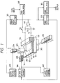
- Fig. 1 illustrates a main constitution of the recording medium and the access method of the present invention.
- the numeral 101 denotes a substrate of the recording medium; 102 a lower electrode; 103 a recording layer; 104 an electrode pattern of edge formation; 121 a recording-reproducing region; and 120 an edge portion.
- a stage 201 supporting a recording medium is driven in the Y-axis direction by a linear actuator 206.
- a recording-reproducing head 203 supports a probe electrode 202, and is controlled in position by actuators 205 and 204 driving respectively in X-direction and Z-direction.
- the distance between the surface of the recording medium and the probe electrode is controlled according to a tunnel current flowing between the surface of the recording medium and the probe electrode in such a manner that a tunnel current caused by the bias voltage V B is detected by a loading resistance R L , and is amplified by an amplifier 301, an appropriate probe height is decided by a probe-height-detecting circuit 302, and the probe height is adjusted by a Z-axis driving control circuit.
- a recording-reproducing region 121 is decided based on the edge 120.
- the X-axis driving control circuit 306 and the actuator 205 drive the probe electrode 202 to scan along X-axis direction.
- the tunnel current abruptly increases between the probe electrode and the edge portion. This abrupt increase of the tunnel current is detected by an edge-detecting circuit 303.
- the detection signal reverses the scanning direction of the probe. After lapse of a predetermined time, the probe electrode reverses the scanning direction to scan toward the edge portion. On this reversal, a drive signal is sent to the Y-axis driving control circuit to shift the stage by one step width.
- the probe electrode is allowed to scan the recording-reproducing region invariably along the edge portion at a certain angle to the edge portion.
- a writing voltage (a pulse voltage) is applied to the probe electrode from the data modulation circuit 308 through the switch SW by reference to the time of scanning reversal of the probe electrode to X-axis direction on detecting the edge portion 120.
- a series of data pulses are recorded during the time of scanning by the probe electrode in X-axis direction for a predetermined time until beginning of another scanning reversal toward the edge portion
- the probe electrode conducts scanning by reference to the edge portion in a similar manner as in the recording.
- the azimuth adjustment between the X-axis scanning direction of the probe electrode and the recorded data line may be conducted by a "wobbling method" as disclosed in Japanese Patent Publication No. 54-15727. Otherwise, correction may be made on demodulation of data by pattern-matching or the like technique after two-dimensional region-scanning.
- a bias voltage is applied between the probe electrode and the recording medium.
- Fig. 2A illustrates a state of data recording on a surface of a recording medium.
- the numeral 122 denotes a recording bit of data; 123 (solid arrow line) a locus of the tip of the probe electrode when the probe is made to scan in the direction away from the edge portion; 124 (broken arrow line) a locus of the tip of the probe moving toward the edge portion.
- Fig. 2B illustrates the case where the edge portion 120 is not in a completely straight line but is irregular. Even in such a case, the lined data is written in by following the edge portion without any inconvenience. Therefore, the allowance for accuracy of the shape of the finished edge portion is large, so that the edge may be in any shape such as a stripe, a spiral, and so forth.
- the probe electrode can be brought to any desired data-recording region.
- the probe electrode is not precisely placed at the position of the recording region of the recording medium owing to mechanical inaccuracy of installing. This positional inaccuracy is usually in the range of from 10 to 100 ⁇ m, which is much larger than the size of the recording region.
- scanning by edge detection may facilitate finding of the data region and the tracking.
- the recording layer employed for the recording medium of the present invention may be made of any material, insofar as the recording layer allows detection of the information written thereon by a tunnel current between the probe electrode and the recording layer.
- Examples of the material of the recording layer for recording by recess-projection formation on the surface include HOPG (Highly-Oriented-Pyrolithic-Graphite) cleavage substrates, Si wafers, metal thin films of Au, Ag, Pt, Mo, Cu, or the like formed by vacuum vapor deposition or epitaxial growth, and glassy metals like Rh25Zr75 and Co35Tb65.
- Examples of the material for recording by surface electronic state include thin film layers of amorphous Si, ⁇ -electron-conjugated organic compounds, and chalcogenoid compounds, and the like.
- the shape of the recording medium and the material of the substrate of the present invention is not limited at all.
- the examples of the shape of the substrates include card-shaped or tape-shaped substrates suitable for forming edge portion in stripe, and disk-shaped substrates suitable for forming edge portions in spiral.
- the examples of the material of the substrates include cleavage crystal substrates such as HOPG, and mica, surface-ground crystal substrates of Si, sapphire, MgO, etc., molten quartz, Corning glass #7059, and so forth.
- substrates for tape-shaped recording medium polycarbonate resins, acrylic resins, PEEK, PET, nylons, may be used.
- Fig. 3 illustrates a first embodiment of the recording medium of the present invention. The embodiment is described below by reference to the figure.
- the numeral 101 denotes a substrate; 102 a lower electrode; 103 a recording layer; and 104 electrodes which forms an edge.
- the probe electrode is introduced from the point "a”, and conduct scanning successively along the edge of the stripe-shaped electrode 104, and thereafter is brought out from the point "b".
- the edge portion formed by the electrode 104 expands in a funnel shape to compensate the setting deviation between the probe electrode and the recording medium. Therefore, the probe electrode is guided by the funnel-shaped edge into the recording region.
- a substrate 101 of mica having been cleaved in the air gold is made to grow epitaxially throughout the surface by vacuum deposition to form a lower electrode layer 102.
- the formation of the lower electrode layer was conducted at the conditions of a substrate temperature of 500°C, deposition rate of 10 ⁇ /sec, deposition pressure of 5 ⁇ 10 ⁇ 6 Torr, and film thickness of 5000 ⁇ .
- a two-layered monomolecular built-up film of polyimide in thickness of 8 ⁇ is formed as a recording layer 103 by a Langmuir-Blodgett method.
- the polyamic acid represented by the formula (3) below is dissolved in N,N-dimethylacetamide (at the concentration of 1 ⁇ 10 ⁇ 3M in terms of the monomer).
- 1 ⁇ 10-3M N,N-dimethyloctadecylamine solution in the same solvent is mixed at a mixing ratio of 1:2 (V/V) to prepare a solution of the octadecylamine salt of the polyamic acid represented by the formula (4)
- This solution is spread over the aqueous phase consisting of pure water at a temperature of 20°C to form a monomolecular film on the surface of water. After evaporation of the solvent, the surface pressure was raised up to 25 mN/m.
- the aforementioned substrate having the lower electrode was dipped slowly into the water in a direction crossing the water surface at a rate of 5 mm/min, and then pulled up at a rate of 5 mm/min to form a two-layered Y-type monomolecular built-up film. Thereafter, the substrate is subjected to heat treatment of 300°C for 10 minutes to convert the octadecylamine salt of the polyamic acid into an imide as shown in the formula (5), thereby forming a two-layered polyimide monomolecular built-up film. Subsequently, as illustrated in Fig.
- the recording medium of Example 1 of the present invention is advantageous as below:
- FIG. 4 A second second embodiment of the recording medium of the present invention is illustrated in Fig. 4.
- the numeral 101 denotes a substrate; 102 a lower electrode which forms the edge portion; and 103 a recording layer.
- a probe electrode 202 moves in a direction perpendicular to a stripe of the edge portion to make access to a desired track, namely a stripe in the edge portion. In each track, the probe electrode scans along the edge portion: in this example, the projecting side of the recording layer is the recording-reproducing region.
- a mica substrate 101 having been cleaved in the air to form an electrode layer 102.
- the formation of the electrode layer 102 is conducted under the conditions of the substrate temperature of 500°C, the deposition rate of 10 ⁇ /sec, the pressure of vapor deposition of 5 ⁇ 10 ⁇ 6 Torr, and the film thickness of 5000 ⁇ .
- the electrode layer 102 is etched as shown in Fig. 7B by immersion in an etching solution composed of aqueous potassium iodide according to usual photolithographic etching to form a groove of 1 ⁇ m in line width, 2 ⁇ m in pitch, and 200 ⁇ in depth, which becomes an electrode layer having a stepped portion 120 as the edge portion.
- an etching solution composed of aqueous potassium iodide according to usual photolithographic etching to form a groove of 1 ⁇ m in line width, 2 ⁇ m in pitch, and 200 ⁇ in depth, which becomes an electrode layer having a stepped portion 120 as the edge portion.
- two-layered built-up film of 8 ⁇ thick of a polyimide monomolecular built-up film is formed as a recording layer 103 according to an LB method.
- the polyimide monomolecular built-up film is formed in the same manner as in Recording medium example 1 above.
- the edge portion is formed by the lower electrode, so that the recording layer is not exposed to an etching solution in the photolithographic etching step for the edge formation.
- the recording layer is formed at the final step of production of the recording medium. Accordingly, in this example any kind of material may be employed for the recording layer.
- FIG. 5A is a plan view
- Fig. 5B is a cross-sectional view at the line A-A' in Fig. 5A.
- the numeral 101 denotes a substrate in a disk shape; 102 a lower electrode; 103 a recording medium; and 105 an edge portion formed by ion implantation.
- This edge portion is formed in a spiral shape on a disk-shaped substrate.
- the probe electrode is introduced to the medium while the substrate is rotating, and the probe electrode moves from the periphery to the center of the disk or from the center to the periphery, conducting recording or reproduction.
- Fig. 8A gold is made to grow epitaxially on the whole surface of a mica substrate 101 having been cleaved in the air to form an electrode layer 102.
- the formation of the electrode is conducted under the conditions of the substrate temperature of 500°C, the deposition rate of 10 ⁇ /sec, the pressure of vapor deposition of 5 ⁇ 10 ⁇ 6 Torr, and the film thickness of 5000 ⁇ .
- elemental silicon is injected into the electrode layer 102 in the direction denoted by the arrow marks by means of a focusing ion beam apparatus at an accelerating voltage of 80 kV and at a dose of 1015 ions/cm2 to form a modified portion 105 of 0.1 ⁇ m in width and 1.1 ⁇ m in pitch as the edge portion.
- a two-layered polyimide monomolecular built-up film of 8 ⁇ thick is formed as a recording layer 103 according to an LB method.
- the polyimide monomolecular built-up film is formed in the same manner as in Recording medium example 1 above.
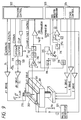
- Fig. 9 illustrates an example of a constitution of a recording-reproducing apparatus for practicing the access method of the present invention.
- Fig. 10A and Fig. 10B illustrate loci of the tip of a probe electrode on a surface of a recording medium.
- Fig. 11 and Fig. 12 show examples of the wave forms of signal lines made by the recording-reproducing apparatus of Fig. 9 at the time of reproduction and recording. The description is made below by reference to figures.
- the numeral 101 denotes a substrate of a recording medium.
- a stage 201 is movable in directions of X, Y, and Z within a range of 10 mm respectively to bring a probe electrode to any desired recording region on the recording medium.
- a cylindrical PZT actuator 210 is provided for scanning of a probe electrode 202 along a data line on the recording medium, and is movable in directions of X, Y, and Z within a range of 2 ⁇ m respectively.
- the probe electrode 202 is connected to a current amplifier 310.
- the output from the current amplifier is inputted to a sample-and-hold circuit 312 via a logarithmic reducer circuit 311.
- An output signal a from the sample-and-hold circuit is inputted to a comparator 313, a peak-hold circuit 314, and a high-pass filter 318, respectively.
- the output b from the peak-hold circuit 314 is connected to an error amplifier 315 and a low-pass filter 316.
- the output from the error amplifier is connected to a ⁇ Z-driving electrode of the cylindrical PZT.
- the output from the low-pass filter 316 is inputted to a comparator 317 via an attenuator VR3.
- the output d of the high-pass filter 318 is connected to another input of the comparator 317. Further, the output of the comparator 317 is inputted to a data modulator of a data modulation-demodulation section 323.
- a data modulation output from the data modulation-demodulation section is connected to a pulse generator 321, and further connected to an electrode of the recording medium in combination with a DC bias voltage V B1 .
- a tracking control section 322 drives the cylindrical PZT actuator 210 through an up/down counter 319 and a D/A converter 320.
- an OR gate for the output of the comparator 313 for edge detection and the up-control signal from the tracking control section 322 is connected.
- the down-input f to the up/down counter 319 the down-control signal of the tracking control section is connected.
- the count output from the up/down counter is converted to analogue voltage by the D/A converter 320, and drives the cylindrical PZT by a distance of ⁇ X.
- the output from the D/A converter 320 after combined with a wobbling signal k through a variable resistance R2 controlled by scanning azimuth control signal l ⁇ and a resistance R1, drives the cylindrical PZT by a distance of ⁇ Y.
- the locus of the probe electrode 202 on the recording medium is as shown of data in Fig. 10A.
- the cylindrical PZT 210 starts scanning from the initial set position 140 of the probe on the stage 201, and scans data along the locus shown by the numeral 141. On detecting the edge 120, the probe reverses the scanning direction and follows the locus 142. After scanning a predetermined distance, it again reverses the scanning direction toward the edge 120.
- the probe electrode When the probe electrode detects the data bit line 122 after the repetition of the above operation, it continues scanning sequentially by adjusting the scanning azimuth to follow the data line.
- the scanning azimuth of the probe electrode is controlled by changing the variable resistance R2 by the scanning azimuth control signal l ⁇ to change the drive ratio of ⁇ X/ ⁇ Y of the cylindrical PZT actuator 210.
- the suitable scanning azimuth is decided, as shown in Fig. 9, by monitoring an envelope signal c holding the tunnel voltage peak resulting from ⁇ Y drive by the wobbling voltage k.
- Fig. 10B shows the state of scanning of the probe electrode over a data line on the recoring medium as a cross-sectional view.
- the distance between the probe electrode and the surface of the recording medium is controlled by comparing a peak-hold value of the logarithmically reduced tunnel current with the reference voltage V B3 , and driving the cylindrical PZT by a distance of ⁇ Z.
- the probe electrode scans so as to envelop the projecting portions or the portions of the highest electron state of the data line.
- the tunnel current detected by the probe electrode is amplified by the current amplifier 310 in Fig. 9, logarithmically reduced by the logarithmic reducer, and then inputted to the sample-and-hold circuit 312.
- This sample-and-hold circuit comes to be in a through state at the time of reproduction to pass directly the output from the logarithmic reducer.
- the access of the probe electrode to the edge is detected by comparing the sample-and-hold output a and the threshold voltage V B2 by an edge-detecting comparator.
- the V B2 is set larger than the output voltage of the data line.
- the signal of edge detection changes the up/down counter forcibly to up-count operation. After a certain number of counts, the counter is changed again to down-count operation.
- the control signals of up and down in the up/down counter is shown by g and f in Fig. 11.
- the output for ⁇ X drive is shown by h in Fig. 11.
- writing operation is started by setting V B3 at a predetermined level.
- the sample-and-hold control signal i is set to the hold state by synchronizing with a data-writing-clock, and the pulse i is generated by the pulse generator 321.
- the writing of the data pulse is continued until the direction of scanning of the probe electrode is reversed.
- the operation is changed to a readout state, and the the data-writing operation is kept standing-by until the next detection of the edge.
- the timing for the recorded data bit is precisely estimated in scanning of a data bit line with a probe electrode for readout. Accordingly the method of the present invention has advantages below.
- the present invention which provides an edge portion on a recording medium and conducting recording data lines two-dimensionally by reference to this edge, gives the advantages below.
- the effects of the present invention satisfies the requirements on the functions of memory of (1) high density and large volume of recording, (2) high response speed in recording-reproducing, and (3) high productivity and low cost.
Applications Claiming Priority (4)
| Application Number | Priority Date | Filing Date | Title |
|---|---|---|---|
| JP10405790 | 1990-04-18 | ||
| JP2104057A JP2783646B2 (ja) | 1990-04-18 | 1990-04-18 | 情報記録再生装置 |
| JP104057/90 | 1990-04-18 | ||
| EP91303423A EP0453263B1 (fr) | 1990-04-18 | 1991-04-17 | Appareil et procédé pour traiter l'information |
Related Parent Applications (2)
| Application Number | Title | Priority Date | Filing Date |
|---|---|---|---|
| EP91303423A Division EP0453263B1 (fr) | 1990-04-18 | 1991-04-17 | Appareil et procédé pour traiter l'information |
| EP91303423.7 Division | 1991-04-17 |
Publications (3)
| Publication Number | Publication Date |
|---|---|
| EP0709836A2 true EP0709836A2 (fr) | 1996-05-01 |
| EP0709836A3 EP0709836A3 (fr) | 1996-05-15 |
| EP0709836B1 EP0709836B1 (fr) | 2000-10-25 |
Family
ID=14370563
Family Applications (2)
| Application Number | Title | Priority Date | Filing Date |
|---|---|---|---|
| EP91303423A Expired - Lifetime EP0453263B1 (fr) | 1990-04-18 | 1991-04-17 | Appareil et procédé pour traiter l'information |
| EP95203410A Expired - Lifetime EP0709836B1 (fr) | 1990-04-18 | 1991-04-17 | Procédé pour accéder à un milieu d'enregistrement, appareil et procédé pour traiter l'information |
Family Applications Before (1)
| Application Number | Title | Priority Date | Filing Date |
|---|---|---|---|
| EP91303423A Expired - Lifetime EP0453263B1 (fr) | 1990-04-18 | 1991-04-17 | Appareil et procédé pour traiter l'information |
Country Status (5)
| Country | Link |
|---|---|
| US (1) | US5199021A (fr) |
| EP (2) | EP0453263B1 (fr) |
| JP (1) | JP2783646B2 (fr) |
| CA (1) | CA2040703C (fr) |
| DE (2) | DE69128257T2 (fr) |
Families Citing this family (11)
| Publication number | Priority date | Publication date | Assignee | Title |
|---|---|---|---|---|
| JPH041948A (ja) * | 1990-04-18 | 1992-01-07 | Canon Inc | 情報記録装置及び情報再生装置及び情報記録再生装置 |
| JP2930447B2 (ja) * | 1991-05-15 | 1999-08-03 | キヤノン株式会社 | 情報処理装置 |
| JP3029143B2 (ja) * | 1991-06-11 | 2000-04-04 | キヤノン株式会社 | 情報再生方法 |
| CA2080251C (fr) * | 1991-10-15 | 1997-12-02 | Shunichi Shido | Appareil de traitement d'informations a mecanisme de centrage |
| JPH06187675A (ja) * | 1992-09-25 | 1994-07-08 | Canon Inc | 情報処理装置、及びそれを用いる情報処理方法 |
| EP0648049A1 (fr) * | 1993-10-08 | 1995-04-12 | Hitachi, Ltd. | Procédé et appareil d'enregistrement et reproduction d'information |
| JPH10188375A (ja) * | 1996-12-17 | 1998-07-21 | Canon Inc | 記録媒体 |
| US6396783B1 (en) * | 1999-09-23 | 2002-05-28 | Terastor Corporation | Mechanism for controlling spacing between optical head and storage medium in optical storage systems |
| US7811499B2 (en) * | 2006-06-26 | 2010-10-12 | International Business Machines Corporation | Method for high density data storage and read-back |
| KR100761059B1 (ko) * | 2006-09-29 | 2007-09-21 | 파크시스템스 주식회사 | 오버행 샘플 측정이 가능한 주사 탐침 현미경 |
| JP6774240B2 (ja) * | 2016-07-14 | 2020-10-21 | 株式会社ミツトヨ | 形状測定装置の制御方法 |
Citations (3)
| Publication number | Priority date | Publication date | Assignee | Title |
|---|---|---|---|---|
| EP0272935A2 (fr) * | 1986-12-24 | 1988-06-29 | Canon Kabushiki Kaisha | Appareil d'enregistrement et appareil de reproduction |
| EP0309236A2 (fr) * | 1987-09-24 | 1989-03-29 | Canon Kabushiki Kaisha | Microsonde, sa préparation et appareil électronique utilisant cette microsonde |
| EP0360337A2 (fr) * | 1988-09-21 | 1990-03-28 | Koninklijke Philips Electronics N.V. | Procédé et dispositif pour l'usinage à l'échelle des submicrons d'une surface de matériau |
Family Cites Families (12)
| Publication number | Priority date | Publication date | Assignee | Title |
|---|---|---|---|---|
| US4575822A (en) * | 1983-02-15 | 1986-03-11 | The Board Of Trustees Of The Leland Stanford Junior University | Method and means for data storage using tunnel current data readout |
| US4829507A (en) * | 1984-09-14 | 1989-05-09 | Xerox Corporation | Method of and system for atomic scale readout of recorded information |
| US4878213A (en) * | 1984-09-14 | 1989-10-31 | Xerox Corporation | System for recording and readout of information at atomic scale densities and method therefor |
| JPS6180536A (ja) * | 1984-09-14 | 1986-04-24 | ゼロツクス コーポレーシヨン | 原子規模密度情報記緑および読出し装置並びに方法 |
| GB8526866D0 (en) * | 1985-10-31 | 1985-12-04 | Emi Plc Thorn | Information recovery system |
| JPS63261554A (ja) * | 1987-04-20 | 1988-10-28 | Hitachi Ltd | 情報記憶装置 |
| JP2703765B2 (ja) * | 1987-08-25 | 1998-01-26 | 三菱電機株式会社 | 書替可能光磁気デイスク |
| JP2603270B2 (ja) * | 1987-08-25 | 1997-04-23 | キヤノン株式会社 | 記録装置および再生装置 |
| JPH01107341A (ja) * | 1987-10-21 | 1989-04-25 | Hitachi Ltd | 電子線記録再生装置 |
| JP2523144B2 (ja) * | 1987-11-18 | 1996-08-07 | 株式会社日立製作所 | 情報記録再生装置および情報記録媒体 |
| JPH01151035A (ja) * | 1987-12-09 | 1989-06-13 | Hitachi Ltd | 高密度再生装置および記録再生装置 |
| JPH01154332A (ja) * | 1987-12-11 | 1989-06-16 | Nippon Telegr & Teleph Corp <Ntt> | 記憶媒体およびトラッキング方法 |
-
1990
- 1990-04-18 JP JP2104057A patent/JP2783646B2/ja not_active Expired - Fee Related
-
1991
- 1991-04-16 US US07/685,643 patent/US5199021A/en not_active Expired - Lifetime
- 1991-04-17 CA CA002040703A patent/CA2040703C/fr not_active Expired - Fee Related
- 1991-04-17 EP EP91303423A patent/EP0453263B1/fr not_active Expired - Lifetime
- 1991-04-17 DE DE69128257T patent/DE69128257T2/de not_active Expired - Fee Related
- 1991-04-17 DE DE69132456T patent/DE69132456T2/de not_active Expired - Fee Related
- 1991-04-17 EP EP95203410A patent/EP0709836B1/fr not_active Expired - Lifetime
Patent Citations (3)
| Publication number | Priority date | Publication date | Assignee | Title |
|---|---|---|---|---|
| EP0272935A2 (fr) * | 1986-12-24 | 1988-06-29 | Canon Kabushiki Kaisha | Appareil d'enregistrement et appareil de reproduction |
| EP0309236A2 (fr) * | 1987-09-24 | 1989-03-29 | Canon Kabushiki Kaisha | Microsonde, sa préparation et appareil électronique utilisant cette microsonde |
| EP0360337A2 (fr) * | 1988-09-21 | 1990-03-28 | Koninklijke Philips Electronics N.V. | Procédé et dispositif pour l'usinage à l'échelle des submicrons d'une surface de matériau |
Also Published As
| Publication number | Publication date |
|---|---|
| CA2040703A1 (fr) | 1991-10-19 |
| EP0453263B1 (fr) | 1997-11-26 |
| DE69132456D1 (de) | 2000-11-30 |
| EP0453263A1 (fr) | 1991-10-23 |
| DE69132456T2 (de) | 2001-05-03 |
| EP0709836B1 (fr) | 2000-10-25 |
| JP2783646B2 (ja) | 1998-08-06 |
| DE69128257T2 (de) | 1998-04-09 |
| CA2040703C (fr) | 1997-06-03 |
| JPH041947A (ja) | 1992-01-07 |
| EP0709836A3 (fr) | 1996-05-15 |
| DE69128257D1 (de) | 1998-01-08 |
| US5199021A (en) | 1993-03-30 |
Similar Documents
| Publication | Publication Date | Title |
|---|---|---|
| CA2068587C (fr) | Enregistrement et lecture d'informations au moyen d'un microscope a effet tunnel | |
| EP0416920B1 (fr) | Procédé et dispositif de traitement d'information | |
| EP0474433B1 (fr) | Procédé et appareil pour traiter des informations | |
| EP0519745A2 (fr) | Milieu d'enregistrement, appareil de traitement d'information l'utilisant et méthode d'effacement d'information | |
| JP2981804B2 (ja) | 情報処理装置、それに用いる電極基板、及び情報記録媒体 | |
| JPH03156749A (ja) | 記録媒体用基板及びその製造方法、記録媒体、記録方法、記録再生方法、記録装置、記録再生装置 | |
| US5199021A (en) | Method of access to recording medium, and apparatus and method for processing information | |
| JP2744359B2 (ja) | 情報再生及び/又は情報記録装置 | |
| EP0438256B1 (fr) | Appareil de traitement d'information et méthode de traitement d'information. | |
| US5255259A (en) | Method of access to recording medium, and apparatus and method for processing information | |
| EP0518240B1 (fr) | Méthode de reproduction d'information et appareil qui utilise la méthode | |
| US5757760A (en) | Information recording and/or reproducing apparatus and method for performing recording and/or reproduction of information by using probe | |
| EP0449409A2 (fr) | Sonde, appareil de traitement d'information utilisant la sonde, et méthodes d'utilisation et fabrication | |
| JP2872659B2 (ja) | 情報記録再生装置 | |
| JP2961451B2 (ja) | 平滑電極基板及びその製造方法、記録媒体及びその製造方法、及び情報処理装置 | |
| JP3005077B2 (ja) | 記録及び/又は再生方法及び装置 | |
| JPH06333276A (ja) | 記録媒体及びその製造方法、及び該記録媒体を用いた情報処理装置 | |
| JP3004823B2 (ja) | 情報処理装置 | |
| JP3044417B2 (ja) | 情報処理装置 | |
| CA2024725C (fr) | Methode et dispositif de traitement de donnees | |
| JP3000496B2 (ja) | 情報記録方法 | |
| JPH02292752A (ja) | 記録再生装置 | |
| JPH076416A (ja) | 情報処理装置 |
Legal Events
| Date | Code | Title | Description |
|---|---|---|---|
| PUAI | Public reference made under article 153(3) epc to a published international application that has entered the european phase |
Free format text: ORIGINAL CODE: 0009012 |
|
| PUAL | Search report despatched |
Free format text: ORIGINAL CODE: 0009013 |
|
| AC | Divisional application: reference to earlier application |
Ref document number: 453263 Country of ref document: EP |
|
| AK | Designated contracting states |
Kind code of ref document: A2 Designated state(s): BE CH DE ES FR GB IT LI NL SE |
|
| AK | Designated contracting states |
Kind code of ref document: A3 Designated state(s): BE CH DE ES FR GB IT LI NL SE |
|
| 17P | Request for examination filed |
Effective date: 19960925 |
|
| 17Q | First examination report despatched |
Effective date: 19981015 |
|
| GRAG | Despatch of communication of intention to grant |
Free format text: ORIGINAL CODE: EPIDOS AGRA |
|
| GRAG | Despatch of communication of intention to grant |
Free format text: ORIGINAL CODE: EPIDOS AGRA |
|
| GRAG | Despatch of communication of intention to grant |
Free format text: ORIGINAL CODE: EPIDOS AGRA |
|
| GRAH | Despatch of communication of intention to grant a patent |
Free format text: ORIGINAL CODE: EPIDOS IGRA |
|
| GRAH | Despatch of communication of intention to grant a patent |
Free format text: ORIGINAL CODE: EPIDOS IGRA |
|
| GRAA | (expected) grant |
Free format text: ORIGINAL CODE: 0009210 |
|
| AC | Divisional application: reference to earlier application |
Ref document number: 453263 Country of ref document: EP |
|
| AK | Designated contracting states |
Kind code of ref document: B1 Designated state(s): BE CH DE ES FR GB IT LI NL SE |
|
| PG25 | Lapsed in a contracting state [announced via postgrant information from national office to epo] |
Ref country code: NL Free format text: LAPSE BECAUSE OF FAILURE TO SUBMIT A TRANSLATION OF THE DESCRIPTION OR TO PAY THE FEE WITHIN THE PRESCRIBED TIME-LIMIT Effective date: 20001025 Ref country code: LI Free format text: LAPSE BECAUSE OF FAILURE TO SUBMIT A TRANSLATION OF THE DESCRIPTION OR TO PAY THE FEE WITHIN THE PRESCRIBED TIME-LIMIT Effective date: 20001025 Ref country code: ES Free format text: THE PATENT HAS BEEN ANNULLED BY A DECISION OF A NATIONAL AUTHORITY Effective date: 20001025 Ref country code: CH Free format text: LAPSE BECAUSE OF FAILURE TO SUBMIT A TRANSLATION OF THE DESCRIPTION OR TO PAY THE FEE WITHIN THE PRESCRIBED TIME-LIMIT Effective date: 20001025 Ref country code: BE Free format text: LAPSE BECAUSE OF FAILURE TO SUBMIT A TRANSLATION OF THE DESCRIPTION OR TO PAY THE FEE WITHIN THE PRESCRIBED TIME-LIMIT Effective date: 20001025 |
|
| REG | Reference to a national code |
Ref country code: CH Ref legal event code: EP |
|
| REF | Corresponds to: |
Ref document number: 69132456 Country of ref document: DE Date of ref document: 20001130 |
|
| ET | Fr: translation filed | ||
| ITF | It: translation for a ep patent filed |
Owner name: SOCIETA' ITALIANA BREVETTI S.P.A. |
|
| PG25 | Lapsed in a contracting state [announced via postgrant information from national office to epo] |
Ref country code: SE Free format text: LAPSE BECAUSE OF FAILURE TO SUBMIT A TRANSLATION OF THE DESCRIPTION OR TO PAY THE FEE WITHIN THE PRESCRIBED TIME-LIMIT Effective date: 20010125 |
|
| NLV1 | Nl: lapsed or annulled due to failure to fulfill the requirements of art. 29p and 29m of the patents act | ||
| REG | Reference to a national code |
Ref country code: CH Ref legal event code: PL |
|
| PLBE | No opposition filed within time limit |
Free format text: ORIGINAL CODE: 0009261 |
|
| STAA | Information on the status of an ep patent application or granted ep patent |
Free format text: STATUS: NO OPPOSITION FILED WITHIN TIME LIMIT |
|
| 26N | No opposition filed | ||
| REG | Reference to a national code |
Ref country code: GB Ref legal event code: IF02 |
|
| PGFP | Annual fee paid to national office [announced via postgrant information from national office to epo] |
Ref country code: GB Payment date: 20040405 Year of fee payment: 14 |
|
| PGFP | Annual fee paid to national office [announced via postgrant information from national office to epo] |
Ref country code: FR Payment date: 20040421 Year of fee payment: 14 Ref country code: DE Payment date: 20040421 Year of fee payment: 14 |
|
| PG25 | Lapsed in a contracting state [announced via postgrant information from national office to epo] |
Ref country code: IT Free format text: LAPSE BECAUSE OF NON-PAYMENT OF DUE FEES;WARNING: LAPSES OF ITALIAN PATENTS WITH EFFECTIVE DATE BEFORE 2007 MAY HAVE OCCURRED AT ANY TIME BEFORE 2007. THE CORRECT EFFECTIVE DATE MAY BE DIFFERENT FROM THE ONE RECORDED. Effective date: 20050417 Ref country code: GB Free format text: LAPSE BECAUSE OF NON-PAYMENT OF DUE FEES Effective date: 20050417 |
|
| PG25 | Lapsed in a contracting state [announced via postgrant information from national office to epo] |
Ref country code: DE Free format text: LAPSE BECAUSE OF NON-PAYMENT OF DUE FEES Effective date: 20051101 |
|
| GBPC | Gb: european patent ceased through non-payment of renewal fee |
Effective date: 20050417 |
|
| PG25 | Lapsed in a contracting state [announced via postgrant information from national office to epo] |
Ref country code: FR Free format text: LAPSE BECAUSE OF NON-PAYMENT OF DUE FEES Effective date: 20051230 |
|
| REG | Reference to a national code |
Ref country code: FR Ref legal event code: ST Effective date: 20051230 |