EP0709748B1 - Entwicklungsanordnung - Google Patents
Entwicklungsanordnung Download PDFInfo
- Publication number
- EP0709748B1 EP0709748B1 EP95115366A EP95115366A EP0709748B1 EP 0709748 B1 EP0709748 B1 EP 0709748B1 EP 95115366 A EP95115366 A EP 95115366A EP 95115366 A EP95115366 A EP 95115366A EP 0709748 B1 EP0709748 B1 EP 0709748B1
- Authority
- EP
- European Patent Office
- Prior art keywords
- toner
- carrying roller
- developing device
- toner carrying
- roller
- Prior art date
- Legal status (The legal status is an assumption and is not a legal conclusion. Google has not performed a legal analysis and makes no representation as to the accuracy of the status listed.)
- Expired - Lifetime
Links
Images


Classifications
-
- G—PHYSICS
- G03—PHOTOGRAPHY; CINEMATOGRAPHY; ANALOGOUS TECHNIQUES USING WAVES OTHER THAN OPTICAL WAVES; ELECTROGRAPHY; HOLOGRAPHY
- G03G—ELECTROGRAPHY; ELECTROPHOTOGRAPHY; MAGNETOGRAPHY
- G03G15/00—Apparatus for electrographic processes using a charge pattern
- G03G15/06—Apparatus for electrographic processes using a charge pattern for developing
- G03G15/08—Apparatus for electrographic processes using a charge pattern for developing using a solid developer, e.g. powder developer
- G03G15/0805—Apparatus for electrographic processes using a charge pattern for developing using a solid developer, e.g. powder developer on a brush
-
- G—PHYSICS
- G03—PHOTOGRAPHY; CINEMATOGRAPHY; ANALOGOUS TECHNIQUES USING WAVES OTHER THAN OPTICAL WAVES; ELECTROGRAPHY; HOLOGRAPHY
- G03G—ELECTROGRAPHY; ELECTROPHOTOGRAPHY; MAGNETOGRAPHY
- G03G15/00—Apparatus for electrographic processes using a charge pattern
- G03G15/06—Apparatus for electrographic processes using a charge pattern for developing
- G03G15/08—Apparatus for electrographic processes using a charge pattern for developing using a solid developer, e.g. powder developer
- G03G15/0822—Arrangements for preparing, mixing, supplying or dispensing developer
-
- G—PHYSICS
- G03—PHOTOGRAPHY; CINEMATOGRAPHY; ANALOGOUS TECHNIQUES USING WAVES OTHER THAN OPTICAL WAVES; ELECTROGRAPHY; HOLOGRAPHY
- G03G—ELECTROGRAPHY; ELECTROPHOTOGRAPHY; MAGNETOGRAPHY
- G03G15/00—Apparatus for electrographic processes using a charge pattern
- G03G15/22—Apparatus for electrographic processes using a charge pattern involving the combination of more than one step according to groups G03G13/02 - G03G13/20
- G03G15/34—Apparatus for electrographic processes using a charge pattern involving the combination of more than one step according to groups G03G13/02 - G03G13/20 in which the powder image is formed directly on the recording material, e.g. by using a liquid toner
- G03G15/344—Apparatus for electrographic processes using a charge pattern involving the combination of more than one step according to groups G03G13/02 - G03G13/20 in which the powder image is formed directly on the recording material, e.g. by using a liquid toner by selectively transferring the powder to the recording medium, e.g. by using a LED array
- G03G15/346—Apparatus for electrographic processes using a charge pattern involving the combination of more than one step according to groups G03G13/02 - G03G13/20 in which the powder image is formed directly on the recording material, e.g. by using a liquid toner by selectively transferring the powder to the recording medium, e.g. by using a LED array by modulating the powder through holes or a slit
Definitions
- the present invention relates to a developing device for use in an image forming apparatus for printing image data (for example, characters and drawings) output by a computer, word processor, facsimile machine, etc., on a recording medium such as a sheet, according to the preamble of claim 1.
- image data for example, characters and drawings
- a computer word processor, facsimile machine, etc.
- Such a developing device is known from US-PS-5,233,392.
- An electrophotographic method is widely used as a method for forming image data as a visible image on a recording medium such as a sheet.
- a photoconducting surface of a photoreceptor is uniformly charged.
- the image data of a document is converted into image information carrying light by a semiconductor laser device, an LED head and so on.
- the light is applied to the photoreceptor which has been uniformly charged.
- the charge on the photoreceptor surface is attenuated according to the intensity of the applied light, and an electrostatic latent image is formed.
- the electrostatic latent image is visualized by bringing charged toner into contact with the electrostatic latent image or causing the toner to fly to the electrostatic latent image, thereby forming a toner image.
- the toner image is electrostatically transferred to a sheet, and fixed on the sheet using heat and pressure so as to complete an imaging process on the sheet.
- Japanese Publication for PCT Application No. 503221/1989 proposes a method in which matrix electrodes capable of selectively applying a voltage to a development section are disposed and a toner image is directly formed on a sheet by causing toner to fly according to image data with an electric field which is generated by an application of a voltage corresponding to the image data to the matrix electrodes.
- a control grid is disposed in the developing section.
- the toner is carried on the surface of a toner carrying roller, and supplied to the development section with a rotation of the toner carrying roller.
- Various publications disclose methods for supplying toner to the developing device.
- Japanese Publication for Unexamined Patent Application No. 44457/1983 discloses a method in which an alternating electric field is applied to a section between the toner carrying roller and the control grid, and toner is transported in a cloud state.
- Japanese Publication for Unexamined Patent Application No. 114974/1983 discloses a method for transporting toner with the flow of air.
- Japanese Publication for Unexamined Patent Application No. 168767/1991 proposes a technique for dropping toner onto a sheet passing through a back electrode by giving mechanical vibrations to the toner with an application of a variable voltage to a control grid at the time imaging is not performed, and a technique for bringing the toner back to the toner carrying roller by applying to the control grid a voltage of the same polarity as that of the charging potential of the toner and generating an electric field whose direction is opposite to that generated during imaging in a section between the control grid and the toner carrying roller.
- a developing device of the present invention includes:
- Imaging using the developing device of the above-mentioned structure is performed as follows. First, the toner is charged to a predetermined potential by friction using the toner supply roller. The charged toner flies from the toner carrying roller toward the back electrode due to an electric field formed by the back electrode. At this time, a varying voltage according to the image data to be formed is applied to the grid electrode disposed between the toner carrying roller and the back electrode under control by the controlling means. This influences the flying of toner, and thus the amount of the flying toner varies depending on the image data at each gate of the grid electrode. Namely, the controlling means controls the amount of toner passing through each gate to vary according to the image data to be formed. Consequently, by transporting a recording medium to a section between the grid electrode and the back electrode, the flying toner adheres to the recording medium and a toner image is formed on the recording medium.
- the toner carrying roller has a brush-like shape and since the surface carrying the toner has an increased area, it is possible to carry an increased amount of toner on the roller surface.
- the toner supply roller is disposed to come into contact with the toner carrying roller, it is possible to sufficiently charge the toner by friction with a rubbing action between the toner carrying roller and the toner supply roller. As a result, a sufficient amount of toner can be always supplied to the toner carrying roller.
- the sufficiently charged toner produces repulsion against the toner supply roller and moves in a direction escaping from the toner supply roller. Namely, in an area of the surface of the toner carrying roller which is being separated from the toner supply roller by its own rotation, since the toner is pressed against the surface of the toner carrying roller, it is possible to carry a sufficient amount of toner on the surface of the toner carrying roller.
- the toner carrying roller into a brush-like shape, disposing the toner supply roller to come into contact with the toner carrying roller and applying the voltage having the same polarity of the charging polarity of the toner to the toner supply roller, it is possible to carry a sufficient amount of toner on the surface of the toner carrying roller. As a result, the sufficient amount of toner can continue to be transported to the recording medium and a toner image is stably formed without variations in the image density. In addition, since this structure prevents the toner from flying disorderly, it is possible to form quality toner images. Moreover, even if the force for flying the toner from the toner carrying roller toward the back electrode is small, it is possible to cause a sufficient among of toner to fly.
- This arrangement since the applied voltage to the back electrode can be set low, a high-voltage source is not required, thereby achieving an inexpensive small-size structure.
- This arrangement also prevents variations in the density of the toner image, particularly, a lowering of the density in the latter half of the toner image when forming a high-density toner image, thereby forming a quality toner image.
- a part of the surface of the toner carrying roller comes closer to the toner supply roller with a rotation of the toner carrying roller after causing the toner to fly in a pattern corresponding to the image data in the development section.
- the residual toner is removed from the surface of the toner carrying roller by repulsion against the toner supply roller because the voltage having the same polarity as the charging polarity of the toner is applied to the toner supply roller.
- the above-mentioned part of the surface of the toner carrying roller is separated from the toner supply roller and faces the development section. Since the residual toner (image memory) of the previous toner image is removed after development, a quality toner image can be formed.
- the toner carrying roller is rotated in a forward direction with respect to the transport direction of the recording medium.
- the rotation speed of the toner carrying roller is preferably set so that the moving speed of the surface of the toner carrying roller is higher than the moving speed of the recording medium.
- non-magnetic toner is preferably used.
- the non-magnetic toner since magnetic powder can never adhere to a sheet during imaging, it is possible to form a quality image with clear color.
- this structure further includes moving means for moving the toner carrying roller to a position where the toner carrying roller comes into contact with the grid electrode and that the grid electrode is cleaned with the rotating toner carrying roller.
- the toner carrying roller is moved to come into contact with the grid electrode by the moving means, and rotated.
- the brush section of the toner carrying roller rubs on the surface of the grid electrode, the toner adhering to the surface of the grid electrode is cleaned. It is therefore not necessary to additionally provide a member for cleaning the grid electrode. Consequently, the number of parts is reduced, and an inexpensive small-size structure is achieved. Furthermore, since the toner adhering to the grid electrode can be cleaned, it is possible to prevent an image from having a blank portion due to the adhering toner, thereby forming a quality toner image.
- Fig. 1 is a view schematically showing the structure of an image forming apparatus including a developing device of the present invention.
- Fig. 2 is a cross section showing the structure of a developing device according to one embodiment of the present invention.
- Fig. 3 is a perspective view showing the vicinity of a development section of the developing device.
- Fig. 4 is a plan view showing the structure of a grid electrode.
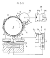
- Fig. 5 is an explanatory view showing an operation for forming an image using the developing device.
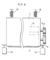
- Fig. 6 is an explanatory view showing essential sections of a moving mechanism of the developing device.
- FIG. 1 schematically shows the structure of an image forming apparatus including a developing device of the present invention.
- the image forming apparatus of this embodiment is connected to external devices such as a computer, word processor and facsimile machine, not shown, and receives image data and an imaging start signal from these external devices.
- a paper cassette 2 for storing a plurality of sheets P as recording media of images.
- a feed roller 3 is mounted above an end section of the paper cassette 2, and feeds the sheets P in the paper cassette 2 piece by piece from the topmost sheet.
- the sheet P fed by the feed roller 3 is transported on a transport guide plate 6 by transport rollers 4.
- a back electrode 5 is mounted on a central section of the top surface of the transport guide plate 6.
- a developing device 7 is disposed above the back electrode 5 to face the back electrode 5, and forms a toner image on the sheet P passing through a section between the developing device 7 and the back electrode 5.
- Fig. 2 illustrates one example of the structure of the developing device 7.
- Fig. 3 is a perspective view showing the vicinity of a development section of the developing device 7.
- the developing device 7 includes a toner room 73 for storing toner 76, and a development room 74 facing the back electrode 5.
- a toner supply opening 75 is formed between the toner room 73 and the development room 74.
- Disposed at the opening 75 is a toner supply roller 72 for supplying the toner 76 to a toner carrying roller 71 in the development room 74.
- An opening section is formed on a side of the development room 74 which faces the back electrode 5, and the toner carrying roller 71 is positioned so that a part of its surface is located in the opening section.
- the toner carrying roller 71 has a toner carrying section (brush section) which surrounds a roller-shaped core member made of conducting metal.
- the toner carrying section is formed by a conducting brush-like member.
- the toner carrying section is formed by implanting conducting fibers into a conducting sheet-type material, a cloth having fuzzy conducting fibers on a surface of a conducting sheet-type material, or a conducting resin.
- the toner carrying roller 71 is constructed by attaching the sheet material or the cloth on the metal core.
- the toner carrying roller 71 is constructed by coating the surface of the metal core with an uneven film of the resin.
- the conducting resin is formed by mixing a conducting substance into a synthetic resin so that it is thoroughly dispersed.
- the conducting fibers are fibers made of the conducting resin.
- the synthetic resin examples include polyolefine resins such as polyethylene, polypropylene and polymethyl pentene, fluoroplastics such as polychlorotrifluoroethylene, polyester resins such as polyethylene terephthalate and polybutylene terephthalate, and cellulose resins such as rayon.
- the conducting material which imparts electrical conductivity to the synthetic resin it is possible to use carbon black such as acetylene black, and fine particles of, for example, stannic oxide (IV), indium oxide and potassium titanate.
- conducting rayon fibers with an resistivity of 10 8 ⁇ cm and a thickness of 20 ⁇ m formed by, for example, mixing carbon black into the rayon fibers are used.
- the toner carrying roller 71 is constructed by implanting 6000 conducting rayon fibers per cm 2 of the sheet material and arranging the length of the brush to be substantially 0.5 mm.
- the amount of toner which adheres to the surface of the toner carrying roller 71 and is transported to the development section needs to be sufficient for forming an image.
- the toner carrying roller 71 since the toner carrying roller 71 has a brush-like shape, it is possible to cause a large amount of toner 76 to adhere to the brush section. Namely, since the toner carrying roller 71 three-dimensionally carries the toner 76 on the surface section (toner carrying section) in the shape of a brush, the surface to which the toner 76 adheres becomes larger in a direction orthogonal to the roller axis. Therefore, even when the density of the toner 76 adhering to the surface of the toner carrying roller 71 is low, it is possible to carry a sufficient amount of the toner 76 for imaging.
- the adhesive force of the toner 76 to the surface of the toner carrying roller 71 is represented by the sum of the toner image force and the adhesive force between toner particles. Even when the toner density on the surface of the toner carrying roller 71 is sparse, if the sufficient amount of toner 76 is carried, an adhesive force between toner particles among the adhesive forces of the toner 76 to the toner carrying roller 71 is reduced, and substantially only the toner image force is present, thereby decreasing the adhesive forces of the toner 76 to the toner carrying roller 71. As a result, the toner 76 tends to fly from the surface of the toner carrying roller 71, the force for causing the toner 76 to fly toward the back electrode 5 becomes smaller.
- the toner carrying roller 71 is supported so that it is freely rotatable in the forward direction in the transport direction of the sheets P.
- the peripheral velocity of the toner carrying roller 71 is set slightly higher than the transport speed of the sheets P.
- the metal core of the toner carrying roller 71 is grounded or connected to a power source having a potential similar to the charging potential of the toner 76.
- the toner supply roller 72 is a conducting resilient roller including a core member made of a conducting metal roller and a conducting resilient member surrounding the core member.
- an urethane resin foam covered with a conducting urethane rubber is preferable as the resilient member.
- the resistivity of the toner supply roller 72 is set lower than the resistivity of the toner carrying roller 71. For example, it is set around 10 3 ⁇ cm.
- the rotation direction of the toner supply roller 72 is equal to the rotation direction of the toner carrying roller 71 as shown in Fig. 2.
- the peripheral velocity of the toner supply roller 72 is set slightly higher than that of the toner carrying roller 71.
- the toner supply roller 72 is connected to the power source section 77.
- the power source section 77 includes a switching circuit (polarization switching means) 77a and a voltage generating section (voltage applying means) 77b, and selectively applies a voltage with positive polarity or negative polarity to the toner supply roller 72.
- the toner 76 has a negative charge, and a negative voltage (the same polarity as the charging voltage of the toner 76) is applied to the toner supply roller 72 during development, while a positive voltage (the opposite polarity to the charging voltage of the toner 76) is applied to the toner supply roller 72 in cleaning the grid electrode 8.
- the toner 76 stored in the toner room 73 is a one-component toner of a non-magnetic type, and formed with a diameter of 5 to 20 ⁇ m by dispersing pigment such as carbon and a polar control agent such as metal containing azo dye into a thermoplastic resin such as a polystyrene resin and acrylic resin and by grinding and classifying the resulting material.
- the toner 76 is charged by friction in an agitating action performed by the rotation of the toner supply roller 72 and the toner carrying roller 71.
- the charging polarity of the toner 76 may be changed to positive by selecting different materials.
- the magnetic powder can never adhere to the sheet P during imaging, thereby preventing the resulting image from having blank and turbid portions.
- Magnetic toner contains magnetic powder for carrying toner particles. Consequently, when magnetic toner is used, the magnetic powder is mixed into the image. This causes turbid colors and an extremely ugly image especially when forming a color image.
- the toner 76 containing no magnetic powder since the toner 76 containing no magnetic powder is used, the above-mentioned problem can never occur, and therefore the resulting image has satisfactory quality. Namely, a clear color image without turbid colors is obtained.
- an additive such as a charge control agent.
- the grid electrode 8 is disposed between the developing device 7 and the transport guide plate 6.
- the grid electrode 8 includes a control substrate 8a having a control circuit, and a plurality of control electrodes 8b and gates 8c on the control substrate 8a.
- Fig. 4 is a plan view showing the structure of the grid electrode 8.
- the control substrate 8a includes a plurality of gates 8c-1, 8c-2, .... 8c-2560 in the shape of circular holes.
- the grid electrode 8 includes 2560 gates 8c in the shape of circular holes.
- the number of gates 8c is suitably arranged according to the size (imaging width) of the image forming apparatus and the resolution of an image to be formed.
- the gates 8c are disposed so that each group of the gates 8c is aligned diagonally with respect to the axis direction of the toner carrying roller 71. As a result, adjacent gates 8c (for example, 8c-1 and 8c-2) can never overlap each other. As illustrated in Fig.
- the control electrode 8b is disposed in the periphery of each of the gates 8c-1, 8c-2, ⁇ .
- the control electrodes 8b are connected to a driver IC 8d for applying a voltage to the control electrodes 8b.
- the control electrodes 8b and the driver IC 8d form controlling means.
- the driver IC 8d includes a serial-to-parallel converter for converting an image data signal input as a serial signal into a predetermined number of parallel signals, and a voltage converter for converting the voltage of the parallel signals into a predetermined voltage.
- the driver IC 8d applies the voltage to the corresponding control electrodes 8b.
- different voltages are applied to the gates 8c-1, 8c-2, ...., respectively, and the amount of toner 76 passing each gate 8c is individually controlled.
- the control electrodes 8b of the grid electrode 8 are connected to a power source section 9 through the driver IC 8d.
- the power source section 9 includes a switching circuit 9a and a power source switching section 9b, and selectively connects the control electrodes 8b to a negative potential (the same polarity as the charging voltage of the toner 76) or an earth potential through the driver IC 8d. More specifically, the control electrodes 8b are connected to a negative power source 91 during a normal imaging process.
- the negative power source 91 has a voltage conversion capability, and switches the voltage value according to the image data to be formed.
- the control electrodes 8b are connected to the earth potential when forming a dot.
- the control electrodes 8b are connected to a negative potential (the same polarity as the charging voltage of the toner 76) during cleaning.
- the back electrode 5 is disposed in the transport guide plate 6 along the axis direction of the toner carrying roller 71.
- the back electrode 5 is connected to a positive power source 51 (the opposite polarity to the charging voltage of the toner 76), and the toner 76 on the toner carrying roller 71 is attracted by the back electrode 5 and flies.
- the sheet P fed from the paper cassette 2 is transported in the direction of an arrow shown in Fig. 2, and passes through a section between the grid electrode 8 and the back electrode 5.
- an amount of the toner 76 adheres to the sheet P in a shape corresponding to the image data, thereby forming a toner image on the sheet P.
- the entire body of the developing device 7 is movable in upward and downward directions.
- a solenoid 78 is mounted on both sides of the developing device 7 facing the toner carrying roller 71, and extension springs 79 for pulling up the developing device 7 is mounted on the upper section thereof.
- the solenoids 78 and the extension springs 79 form moving means.
- the solenoids 78 are turned off, the developing device 7 is pulled up by the tensile forces of the springs 79 to the position shown in Fig. 2, i.e., the imaging position.
- the developing device 7 is pulled down against the tensile forces of the springs 79, and moved to a position where the toner carrying roller 71 in the developing device 7 comes into contact with the grid electrode 8.
- the entire body of the developing device 7 is movable.
- an output tray 11 for the discharge of a sheet having an image formed thereon is installed on the left side of the main body 1 of the image forming apparatus, and a fixing device 10 is disposed between the output tray 11 and the transport guide plate 6.
- the fixing device 10 is formed by a heating roller 10a and a pressure roller 10b.
- a heating source including a halogen lamp heats the surface of the heating roller 10a to a toner fixing temperature (around 180 °C).
- the pressure roller 10b is pressed against the heating roller 10a.
- An image formed by the toner on the sheet P is fused by the heating roller 10a and the pressure roller 10b.
- a motor 12 for supplying a rotative force to a rotating system including the feed roller 3 and the transport rollers 4, and a control unit 13 incorporating a control circuit which controls the main body 1.
- the control unit 13 includes an interface section, an engine control section, and an image signal processing section.
- External devices such as a computer, word processor and facsimile machine (not shown) output signals including image data and an imaging start signal when forming an image.
- the interface section installed in the control unit 13 in the main body 1 receives the signals.
- the interface section detects the imaging start signal among the signals, and sends the signal to the engine control section.
- the operational procedure in the image forming apparatus was programmed in advance in the engine control section, and imaging operations are sequentially carried out according to the program. Referring now to Fig. 5, the following description discusses the imaging operations.
- a motor (not shown) in the developing device 7 is rotated to rotate the toner carrying roller 71 and the toner supply roller 72 so as to charge the toner 76 to a predetermined polarity.
- the toner 76 is agitated with the rotations of the rollers 71 and 72, and charged to a predetermined polarity by friction against the rollers 71 and 72.
- the sufficiently charged toner 76 is supplied to the toner carrying roller 71 by the toner supply roller 72.
- the toner supply roller 72 is connected to a power source (negative power source) having the same polarity as the charging polarity of the toner 76.
- the toner 76 moves to the toner carrying roller 71 by repulsion between the frictionally charged toner 76 and the toner supply roller 72. With the movement of the toner 76, large amounts of the toner 76 adheres to a portion of the toner carrying roller 71, which is being separated from the toner supply roller 72. As a result, the toner carrying roller 71 faces the development section (the facing sections of the grid electrode 8 and the back electrode 5) while carrying a sufficient amount of the toner 76.
- the rotation direction of the toner supply roller 72 is equal to the rotation direction of the toner carrying roller 71.
- the peripheral velocity of the toner supply roller 72 is set slightly higher than that of the toner carrying roller 71.
- the feed roller 3 and the transport rollers 4 are rotated with a rotation of the motor 12 in the main body 1 of the image forming apparatus, and the sheet P in the paper cassette 2 is fed and transported to the development section.
- the sheet P passes through the section between the grid electrode 8 and the back electrode 5.
- an image is formed by the toner 76 flown from the toner carrying roller 71.
- the back electrode 5 is connected to the positive power source 51. Therefore, the toner 76 on the toner carrying roller 71 is attracted to the back electrode 5 and flies from the surface of the toner carrying roller 71.
- the peripheral velocity of the toner carrying roller 71 is set higher than the transport speed of the sheet P, even if the applied voltage to the back electrode 5 is relatively low, a sufficient amount of the toner 76 flies toward the back electrode 5.
- the adhesive force of the toner 76 to the toner carrying roller 71 is relatively strong, it is possible to cause a sufficient amount of the toner 76 to fly. Consequently, even when forming a high-density image, it is possible to form an image with a sufficient density by preventing a lowering of the density in the latter half of the image.
- the control electrodes 8b of the grid electrode 8 are connected to the negative power source 91 through the driver IC 8d.
- the control electrode 8b is provided for each of the gates 8c-1, 8c-2 ...., and a negative voltage whose value varies according to the image data is applied to the respective control electrodes 8b.
- a negative voltage whose value varies according to the image data is applied to the respective control electrodes 8b.
- the amount of flying toner 76 differs in each control electrode 8b, i.e., in each gate 8c.
- the flying toner 76 adheres to the transported sheet P, and thus the image is formed on the sheet P.
- the sheet P is further transported to the fixing device 10 where the toner 76 is fixed, and discharged from the main body 1 of the image forming apparatus.
- the toner carrying roller 71 passes through the development section, the toner 76 on the surface thereof adheres to the sheet P in a pattern corresponding to the image data. Therefore, residual toner (image memory) remains in the pattern corresponding to the image on the surface of the toner carrying roller 71 after passing through the development section. After the toner carrying roller 71 on which the image memory remains passes through the development section, it again faces the toner supply roller 72.
- the toner supply roller 72 is connected to the power source having the same polarity as the toner 76.
- the toner carrying roller 71 comes closer to the toner supply roller 72, the toner 76 on the surface of the toner carrying roller 71 receives repulsion from the toner supply roller 72.
- an amount of the toner 76 corresponding to the image memory is removed from the surface of the toner carrying roller 71.
- the toner carrying roller 71 faces the toner supply roller 72, and receives a sufficient amount of the toner 76 when it is separated from the toner supply roller 72.
- the amount of the toner 76 on the surface of the toner carrying roller 71 becomes sufficient at the position where the toner carrying roller 71 is separated from the toner supply roller 72.
- the toner carrying roller 71 faces the development section and development is carried out, it holds residual toner (image memory). Then, when the toner carrying roller 71 comes closer to the toner supply roller 72, an amount of the toner 76 corresponding to the image memory is removed. Thereafter, the amount of the toner 76 becomes sufficient again at the position where the toner carrying roller 71 is separated from the toner supply roller 72.
- the toner carrying roller 71 has a supply of a sufficient amount of the toner 76 and a removal of an amount of the toner 76 corresponding to the image memory in one rotation by the function of the toner supply roller 72. Therefore, in the next rotation, development can be carried out without being influenced by the image memory of the previous rotation while carrying a sufficient amount of the toner 76. It is thus possible to always form a quality image with stability.
- the cleaning of the grid electrode 8 is periodically carried out, for example, during a warm-up period immediately after turning on the main body 1, or every time a predetermined time has elapsed or imaging has performed on a predetermined number of sheets when the power source of the main body 1 is in the ON state.
- cleaning can never be carried out at the time which may influence the imaging process even if a predetermined time has elapsed or imaging has been performed on a predetermined number of sheets. Therefore, for example, when a sequence of imaging processes are in progress, cleaning is carried out at the time the sequence of the processes are completed, the image data sent from a computer is bit-mapped, or at an interval between feeding sheets.
- the grid electrode 8 is always kept clean, thereby forming a quality image with stability.
- the cleaning process is carried out every time a predetermined time has passed or imaging has been performed on a predetermined number of sheets, i.e., if the frequency of cleaning is increased, it is possible to maintain the quality of image at a high level.
- the cleaning of the grid electrode 8 is carried out at a time interval which does not influence the imaging process, for example, during a warm-up period, after completion of a sequence of imaging processes, during bit-mapping of image data, or at an interval between feeding sheets, the operator does not face problems such as a delay of processing.
- the cleaning operation will be explained below.
- the voltage to be applied to the toner supply roller 72 is switched to positive (the polarity opposite to the toner 76), and the toner supply roller 72 and the toner carrying roller 71 are rotated in this state.
- the toner 76 on the surface of the toner carrying roller 71 is attracted and moved by a positive electric potential of the toner supply roller 72.
- the solenoids 78 are turned on to lower the developing device 7 toward the grid electrode 8 so that the brush section of the toner carrying roller 71 comes into contact with the grid electrode 8.
- the toner carrying roller 71 is rotated by coupling with the free joint on the main body 1, and rubs on the grid electrode 8.
- the switching circuit 9a of the power source section 9 is switched so as to apply a negative voltage (the same polarity as the toner 76) to the control electrode 8b of the grid electrode 8.
- a negative voltage the same polarity as the toner 76
- the toner 76 on the grid electrode 8 moves to the toner carrying roller 71 due to repulsion against the grid electrode 8, thereby cleaning the grid electrode 8.
- the toner 76 is removed from the surface of the toner carrying roller 71. Thereafter, cleaning is performed by bringing the toner carrying roller 71 into contact with the grid electrode 8. With this arrangement, it is possible to perform cleaning while preventing the toner 76 on the toner carrying roller 71 from adhering to the grid electrode 8.
- the voltage having the same polarity as the toner 76 to the control electrode 8b of the grid electrode 8 it is possible to efficiently cause the toner 76 adhering to the grid electrode 8 to move to the toner carrying roller 71, thereby improving the cleaning efficiency. In this case, since the toner 76 removed from the grid electrode 8 is held by the brush-like toner carrying roller 71, it is possible to prevent the toner 76 from flying in the main body 1 of the image forming apparatus.
- a toner carrier provided with a raising member is separably attached to an opening section of a control electrode, and cleaning is performed by bringing the toner carrier into contact with the opening section of the control electrode.
- the raising member only scrapes off the toner adhering to the control electrode.
- the brush-like conducting toner carrying roller 71 is used.
- the toner carrying roller 71 is connected to the earth potential, and a negative voltage (the same polarity as that of the toner 76) is applied to the control electrodes 8b of the grid electrode 8. Therefore, the toner 76 adhering to the grid electrode 8 is not only mechanically scrapped off by the toner carrying roller 71, but also separated from the grid electrode 8 by Coulomb repulsion against the control electrodes 8b and moves to the surface of the toner carrying roller 71 which is in contact with the grid electrode 8. It is thus possible to clean the toner 76 adhering to the grid electrode 8 more efficiently than with the conventional structure.
- the toner carrying roller 71 is connected to the earth potential, even if the surface of the grid electrode 8 is charged by the adhering toner 76, it is possible to remove charges on an insulating surface coating the grid electrode 8.
- This structure eliminates conventional problems that sharpness of the image deteriorates due to scattering and variations in the shape of dots to be formed because an electric field forming the image is distorted by charges on the surface of the grid electrode 8.
- the developing device of the present invention aims for continuous transport of a sufficient amount of toner when non-magnetic toner is used, and aims for the formation of quality images in a stable manner with an inexpensive small-size structure.
- the structure of the present invention can be achieved using non-magnetic toner.
- the peripheral velocity of the toner carrying roller 71 is set higher than the sheet transport speed, it is possible to cause a sufficient amount of the toner 76 to fly.
- the amount of flying toner 76 is proportional to the peripheral velocity of the toner carrying roller 71, it is possible to increase the amount of the flying toner 76 with an increase in the peripheral velocity of the toner carrying roller 71. Since a decrease of the flying force is thus compensated, even if the non-magnetic toner is used, it is possible to cause a sufficient amount of the toner 76 to fly and form an image of a satisfactory density without increasing the applied voltage to the back electrode 5.
Claims (22)
- Entwicklungsanordnung, die dafür sorgt, dass Toner fliegt und an einem Aufzeichnungsträger (P) anhaftet, um ein Bild zu erzeugen, mit:gekennzeichnet durcheiner bürstenähnlichen Toner tragenden Walze (71) zum Transportieren geladenen Toners (76), die ein elektrisches Potential entsprechend dem Ladepotential des Toners aufweist, oder die mit Massepotential verbunden ist;einer Tonerzuführwalze (72), die in Kontakt mit der Toner tragenden Walze angeordnet ist, um den Toner durch Reibung zu laden;einer Rückelektrode (5), die so angeordnet ist, dass sie der Toner tragenden Walze zugewandt ist, um dafür zu sorgen, dass der auf der Toner tragenden Walze (71) transportierte Toner durch Erzeugung eines elektrischen Felds fliegt;einer Gitterelektrode (8), die zwischen der Toner tragenden Walze (71) und der Rückelektrode (5) angeordnet ist und mehrere Durchlässe (8c) aufweist, die ein Hindurchtreten des fliegenden Toners ermöglichen; undeiner Steuerungseinrichtung (8b, 8d) zum Steuern der Menge des durch die Durchlässe laufenden Toners durch Anlegen einer variablen Spannung an die Durchlässe entsprechend Daten eines zu erzeugenden Bilds;eine Spannungsanlegeeinrichtung (77) zum Anlegen einer Spannung mit derselben Polarität wie der Ladepolarität des Toners an die Tonerzuführwalze (72).
- Entwicklungsanordnung nach Anspruch 1, bei der die Toner tragende Walze (71) in Vorwärtsrichtung bezüglich der Transportrichtung des Aufzeichnungsträgers (P) gedreht wird.
- Entwicklungsanordnung nach Anspruch 1, bei der die Drehzahl der Toner tragenden Walze (71) so eingestellt ist, dass die Laufgeschwindigkeit einer Oberfläche der Toner tragenden Walze (71) höher als die Laufgeschwindigkeit des Aufzeichnungsträgers (P) ist.
- Entwicklungsanordnung nach Anspruch 1, ferner mit einer Verstelleinrichtung (78, 79) zum Verstellen der Toner tragenden Walze (71) auf eine Position, in der sie in Kontakt mit der Gitterelektrode (8) tritt, wodurch die Gitterelektrode (8) durch Drehen der Toner tragenden Walze (71) gereinigt wird.
- Entwicklungsanordnung nach Anspruch 1, bei der die Drehrichtung der Tonerzuführwalze (72) der Drehrichtung der Toner tragenden Walze (71) entspricht.
- Entwicklungsanordnung nach Anspruch 5, bei der die Umfangsgeschwindigkeit der Tonerzuführwalze (72) höher als die Umfangsgeschwindigkeit der Toner tragenden Walze (71) eingestellt ist.
- Entwicklungsanordnung nach Anspruch 1, bei der der spezifische Widerstand der Tonerzuführwalze (72) niedriger als der spezifische Widerstand der Toner tragenden Walze (71) eingestellt ist.
- Entwicklungsanordnung nach Anspruch 1, bei der die Tonerzuführwalze (72) eine leitende, nachgiebige Walze mit einem Kernelement aus einer leitenden Metallwalze und einem dieses Kernelement umgebenden leitenden, nachgiebigen Element ist.
- Entwicklungsanordnung nach Anspruch 8, bei der das elastische Element dadurch hergestellt wurde, dass die Oberfläche eines Urethanharzschaums mit leitendem Urethankautschuk beschichtet wurde.
- Entwicklungsanordnung nach Anspruch 1, bei der die Toner tragende Walze (71) Leitungseigenschaften aufweist.
- Entwicklungsanordnung nach Anspruch 10, bei der die Toner tragende Walze (71) ein leitendes Kernelement und einen leitenden Bürstenabschnitt aufweist.
- Entwicklungsanordnung nach Anspruch 11, bei der der Bürstenabschnitt eine leitende Material lage und in diese eingesetzte leitende Fasern aufweist.
- Entwicklungsanordnung nach Anspruch 12, bei der die leitenden Fasern durch Einmischen von Ruß in Rayonfasern hergestellt wurden.
- Entwicklungsanordnung nach Anspruch 11, bei der der Bürstenabschnitt eine leitende Materiallage und ein krauses Tuch mit leitenden Fasern aufweist.
- Entwicklungsanordnung nach Anspruch 11, bei der der Bürstenabschnitt einen auf dem Kernelement ausgebildeten leitenden Harzfilm mit ungleichmäßiger Oberfläche aufweist.
- Entwicklungsanordnung nach Anspruch 4, bei der die Verstelleinrichtung (78, 79) die Toner tragende Walze (71) in einer Aufwärmperiode unmittelbar nach dem Einschalten einer Spannungsquelle des Bilderzeugungsgeräts in eine Position verstellt, in der sie in Kontakt mit der Gitterelektrode (8) tritt.
- Entwicklungsanordnung nach Anspruch 4, bei der die Verstelleinrichtung (78, 79) die Toner tragende Walze (71) mit vorbestimmten Zeitintervallen während der Bilderzeugung in eine Position verstellt, in der sie in Kontakt mit der Gitterelektrode (8) tritt.
- Entwicklungsanordnung nach Anspruch 4, bei der die Verstelleinrichtung (78, 79) die Toner tragende Walze (71) jedesmal dann, wenn die Bilderzeugung für eine vorbestimmte Anzahl von Blättern des Aufzeichnungsträgers (P) ausgeführt wurde, in eine Position verstellt, in der sie in Kontakt mit der Gitterelektrode (8) tritt.
- Entwicklungsanordnung nach Anspruch 4, bei der die Verstelleinrichtung (78, 79) die Toner tragende Walze (71) während der Erzeugung einer Bitkarte der Bilddaten in eine Position verstellt, in der sie in Kontakt mit der Gitterelektrode (8) tritt.
- Entwicklungsanordnung nach Anspruch 4, bei der die Verstelleinrichtung (78, 79) die Toner tragende Walze (71) in einem Intervall zwischen dem Zuführen des Aufzeichnungsträgers (P) in eine Position verstellt, in der sie in Kontakt mit der Gitterelektrode (8) tritt.
- Entwicklungsanordnung nach Anspruch 1, ferner mit einer Polarisations-Umschalteinrichtung (9a) zum Umschalten der durch die Spannungsanlegeeinrichtung (77) erzeugten Spannung während des Reinigungsvorgangs auf eine Polarität, die entgegengesetzt zur Ladepolarität des Toners ist.
- Entwicklungsanordnung nach Anspruch 1, bei der die Gitterelektrode (8) während des Reinigungsvorgangs mit einem elektrischen Potential verbunden wird, das dieselbe Polarität wie die Ladepolarität des Toners aufweist.
Applications Claiming Priority (2)
| Application Number | Priority Date | Filing Date | Title |
|---|---|---|---|
| JP267263/94 | 1994-10-31 | ||
| JP6267263A JP3053340B2 (ja) | 1994-10-31 | 1994-10-31 | 現像装置 |
Publications (3)
| Publication Number | Publication Date |
|---|---|
| EP0709748A2 EP0709748A2 (de) | 1996-05-01 |
| EP0709748A3 EP0709748A3 (de) | 1997-05-14 |
| EP0709748B1 true EP0709748B1 (de) | 1999-04-14 |
Family
ID=17442421
Family Applications (1)
| Application Number | Title | Priority Date | Filing Date |
|---|---|---|---|
| EP95115366A Expired - Lifetime EP0709748B1 (de) | 1994-10-31 | 1995-09-28 | Entwicklungsanordnung |
Country Status (4)
| Country | Link |
|---|---|
| US (1) | US5726695A (de) |
| EP (1) | EP0709748B1 (de) |
| JP (1) | JP3053340B2 (de) |
| DE (1) | DE69509037T2 (de) |
Families Citing this family (5)
| Publication number | Priority date | Publication date | Assignee | Title |
|---|---|---|---|---|
| JPH09314889A (ja) * | 1996-05-28 | 1997-12-09 | Sharp Corp | 画像形成装置 |
| JPH1076698A (ja) * | 1996-09-03 | 1998-03-24 | Sharp Corp | 画像形成装置 |
| KR100238688B1 (ko) * | 1997-04-07 | 2000-01-15 | 윤종용 | 전자사진형성장치의 현상제 회수/공급장치 |
| US6144394A (en) * | 1998-04-13 | 2000-11-07 | Matsushita Electric Industrial Co., Ltd. | Image forming method and device |
| EP0978769A1 (de) * | 1998-08-03 | 2000-02-09 | Agfa-Gevaert N.V. | Druckverfahren für eine Vorrichtung zum direkten elektrostatichen Drucken mit Tonerzufuhrmitteln enthaltend eine geladener-Tonertransportrolle, eine magnetische Bürste und eine Reinigungseinheit |
Family Cites Families (16)
| Publication number | Priority date | Publication date | Assignee | Title |
|---|---|---|---|---|
| US4218691A (en) * | 1977-08-30 | 1980-08-19 | Ricoh Company, Ltd. | Recording apparatus with improved counter electrode |
| GB2070981B (en) * | 1980-01-18 | 1984-02-29 | Tokyo Shibaura Electric Co | Developing apparatus |
| JPS57108871A (en) * | 1980-12-25 | 1982-07-07 | Canon Inc | Developing device |
| JPS57142673A (en) * | 1981-02-27 | 1982-09-03 | Sharp Corp | Cleaning method |
| JPS5844457A (ja) * | 1981-09-11 | 1983-03-15 | Canon Inc | 画像記録装置 |
| JPS58114974A (ja) * | 1981-12-28 | 1983-07-08 | Fujitsu Ltd | 粉体オンデマンド記録法 |
| US4948692A (en) * | 1986-03-31 | 1990-08-14 | Seiko Epson Corporation | Combination toner and printer utilizing same |
| SE459724B (sv) * | 1987-12-08 | 1989-07-31 | Larson Prod Ab Ove | Saett och anordning foer att framstaella ett latent elektriskt laddningsmoenster |
| JPH03168767A (ja) * | 1989-11-29 | 1991-07-22 | Kyocera Corp | 画像形成方法 |
| JP2841610B2 (ja) * | 1990-01-12 | 1998-12-24 | ブラザー工業株式会社 | 画像記録装置 |
| JPH04239661A (ja) * | 1991-01-24 | 1992-08-27 | Brother Ind Ltd | 画像形成装置 |
| JPH0542713A (ja) * | 1991-08-19 | 1993-02-23 | Brother Ind Ltd | 記録装置 |
| US5359361A (en) * | 1991-12-24 | 1994-10-25 | Brother Kogyo Kabushiki Kaisha | Image forming apparatus for forming toner images |
| US5606402A (en) * | 1993-12-27 | 1997-02-25 | Sharp Kabushiki Kaisha | Electrostatic image former with improved toner control grid |
| JP3014576B2 (ja) * | 1994-02-04 | 2000-02-28 | シャープ株式会社 | 記録媒体認識装置 |
| JPH0836306A (ja) * | 1994-07-21 | 1996-02-06 | Toshiba Corp | 現像装置 |
-
1994
- 1994-10-31 JP JP6267263A patent/JP3053340B2/ja not_active Expired - Fee Related
-
1995
- 1995-09-27 US US08/534,280 patent/US5726695A/en not_active Expired - Lifetime
- 1995-09-28 EP EP95115366A patent/EP0709748B1/de not_active Expired - Lifetime
- 1995-09-28 DE DE69509037T patent/DE69509037T2/de not_active Expired - Lifetime
Also Published As
| Publication number | Publication date |
|---|---|
| DE69509037T2 (de) | 1999-10-28 |
| EP0709748A2 (de) | 1996-05-01 |
| US5726695A (en) | 1998-03-10 |
| DE69509037D1 (de) | 1999-05-20 |
| JPH08129300A (ja) | 1996-05-21 |
| JP3053340B2 (ja) | 2000-06-19 |
| EP0709748A3 (de) | 1997-05-14 |
Similar Documents
| Publication | Publication Date | Title |
|---|---|---|
| EP0522813B1 (de) | Elektrophotographisches Aufzeichnungsgerät | |
| WO2005094470A2 (en) | Electrophotographic toner regulating member with polymer coating having surface roughness modified by fine particles | |
| US5371578A (en) | Image forming apparatus including means for removing counter charged toner from the charging means | |
| EP0106322B1 (de) | Entwicklungsgerät | |
| EP0709748B1 (de) | Entwicklungsanordnung | |
| JPH11133747A (ja) | 現像装置 | |
| US5512990A (en) | Resonating assembly having a plurality of discrete resonator elements | |
| JPH10119339A (ja) | 直接静電印刷装置及びトナー送出システム | |
| JP2000206770A (ja) | 画像形成装置 | |
| JP3177644B2 (ja) | 画像形成用感光体の帯電方法および画像形成方法 | |
| JP4090894B2 (ja) | 現像装置およびこれを備える画像形成装置 | |
| JP2727850B2 (ja) | 現像装置 | |
| JP3057142B2 (ja) | 現像装置 | |
| JP2000351231A (ja) | 現像装置 | |
| JPH041560Y2 (de) | ||
| JPH0473789B2 (de) | ||
| JP2003094710A (ja) | 画像形成装置 | |
| JP2000305351A (ja) | 一成分トナーの現像装置 | |
| JPH0516419A (ja) | 静電記録装置 | |
| JPH04301668A (ja) | 画像形成装置 | |
| JPH0934260A (ja) | 画像形成装置 | |
| JP2001083811A (ja) | 画像形成装置 | |
| JPH11263035A (ja) | 画像形成方法および画像形成装置 | |
| JPH06167847A (ja) | 画像形成方法 | |
| JPH06118782A (ja) | 画像形成装置 |
Legal Events
| Date | Code | Title | Description |
|---|---|---|---|
| PUAI | Public reference made under article 153(3) epc to a published international application that has entered the european phase |
Free format text: ORIGINAL CODE: 0009012 |
|
| AK | Designated contracting states |
Kind code of ref document: A2 Designated state(s): DE FR GB |
|
| PUAL | Search report despatched |
Free format text: ORIGINAL CODE: 0009013 |
|
| AK | Designated contracting states |
Kind code of ref document: A3 Designated state(s): DE FR GB |
|
| 17P | Request for examination filed |
Effective date: 19970617 |
|
| 17Q | First examination report despatched |
Effective date: 19971118 |
|
| GRAG | Despatch of communication of intention to grant |
Free format text: ORIGINAL CODE: EPIDOS AGRA |
|
| GRAG | Despatch of communication of intention to grant |
Free format text: ORIGINAL CODE: EPIDOS AGRA |
|
| GRAH | Despatch of communication of intention to grant a patent |
Free format text: ORIGINAL CODE: EPIDOS IGRA |
|
| GRAH | Despatch of communication of intention to grant a patent |
Free format text: ORIGINAL CODE: EPIDOS IGRA |
|
| GRAA | (expected) grant |
Free format text: ORIGINAL CODE: 0009210 |
|
| AK | Designated contracting states |
Kind code of ref document: B1 Designated state(s): DE FR GB |
|
| REF | Corresponds to: |
Ref document number: 69509037 Country of ref document: DE Date of ref document: 19990520 |
|
| ET | Fr: translation filed | ||
| PLBE | No opposition filed within time limit |
Free format text: ORIGINAL CODE: 0009261 |
|
| STAA | Information on the status of an ep patent application or granted ep patent |
Free format text: STATUS: NO OPPOSITION FILED WITHIN TIME LIMIT |
|
| 26N | No opposition filed | ||
| REG | Reference to a national code |
Ref country code: GB Ref legal event code: IF02 |
|
| PGFP | Annual fee paid to national office [announced via postgrant information from national office to epo] |
Ref country code: GB Payment date: 20090923 Year of fee payment: 15 |
|
| PGFP | Annual fee paid to national office [announced via postgrant information from national office to epo] |
Ref country code: DE Payment date: 20090923 Year of fee payment: 15 |
|
| PGFP | Annual fee paid to national office [announced via postgrant information from national office to epo] |
Ref country code: FR Payment date: 20091012 Year of fee payment: 15 |
|
| GBPC | Gb: european patent ceased through non-payment of renewal fee |
Effective date: 20100928 |
|
| REG | Reference to a national code |
Ref country code: FR Ref legal event code: ST Effective date: 20110531 |
|
| REG | Reference to a national code |
Ref country code: DE Ref legal event code: R119 Ref document number: 69509037 Country of ref document: DE Effective date: 20110401 |
|
| PG25 | Lapsed in a contracting state [announced via postgrant information from national office to epo] |
Ref country code: FR Free format text: LAPSE BECAUSE OF NON-PAYMENT OF DUE FEES Effective date: 20100930 Ref country code: DE Free format text: LAPSE BECAUSE OF NON-PAYMENT OF DUE FEES Effective date: 20110401 |
|
| PG25 | Lapsed in a contracting state [announced via postgrant information from national office to epo] |
Ref country code: GB Free format text: LAPSE BECAUSE OF NON-PAYMENT OF DUE FEES Effective date: 20100928 |