EP0709254B1 - Elektronisches Informationsübertragungssystem auf stromführenden Leitungen, insbesonders für ein Kraftfahrzeug - Google Patents
Elektronisches Informationsübertragungssystem auf stromführenden Leitungen, insbesonders für ein Kraftfahrzeug Download PDFInfo
- Publication number
- EP0709254B1 EP0709254B1 EP95402332A EP95402332A EP0709254B1 EP 0709254 B1 EP0709254 B1 EP 0709254B1 EP 95402332 A EP95402332 A EP 95402332A EP 95402332 A EP95402332 A EP 95402332A EP 0709254 B1 EP0709254 B1 EP 0709254B1
- Authority
- EP
- European Patent Office
- Prior art keywords
- supply
- communication
- predetermined
- network
- communication system
- Prior art date
- Legal status (The legal status is an assumption and is not a legal conclusion. Google has not performed a legal analysis and makes no representation as to the accuracy of the status listed.)
- Expired - Lifetime
Links
- 238000004891 communication Methods 0.000 title claims description 88
- 239000004020 conductor Substances 0.000 claims description 26
- 238000010200 validation analysis Methods 0.000 claims description 25
- 238000012360 testing method Methods 0.000 claims description 16
- 230000000694 effects Effects 0.000 claims description 7
- 210000000056 organ Anatomy 0.000 description 35
- 238000001514 detection method Methods 0.000 description 14
- 230000005540 biological transmission Effects 0.000 description 13
- 238000010586 diagram Methods 0.000 description 5
- 238000012545 processing Methods 0.000 description 4
- 239000000969 carrier Substances 0.000 description 3
- 230000015654 memory Effects 0.000 description 3
- 238000000034 method Methods 0.000 description 3
- 238000004458 analytical method Methods 0.000 description 2
- 239000000470 constituent Substances 0.000 description 2
- 235000021183 entrée Nutrition 0.000 description 2
- 230000006870 function Effects 0.000 description 2
- 230000007274 generation of a signal involved in cell-cell signaling Effects 0.000 description 2
- 230000004044 response Effects 0.000 description 2
- 230000011664 signaling Effects 0.000 description 2
- 238000006243 chemical reaction Methods 0.000 description 1
- 238000010276 construction Methods 0.000 description 1
- 230000003247 decreasing effect Effects 0.000 description 1
- 238000013461 design Methods 0.000 description 1
- 239000000835 fiber Substances 0.000 description 1
- 239000002184 metal Substances 0.000 description 1
- 230000017105 transposition Effects 0.000 description 1
- 230000002618 waking effect Effects 0.000 description 1
Images


Classifications
-
- B—PERFORMING OPERATIONS; TRANSPORTING
- B60—VEHICLES IN GENERAL
- B60R—VEHICLES, VEHICLE FITTINGS, OR VEHICLE PARTS, NOT OTHERWISE PROVIDED FOR
- B60R16/00—Electric or fluid circuits specially adapted for vehicles and not otherwise provided for; Arrangement of elements of electric or fluid circuits specially adapted for vehicles and not otherwise provided for
- B60R16/02—Electric or fluid circuits specially adapted for vehicles and not otherwise provided for; Arrangement of elements of electric or fluid circuits specially adapted for vehicles and not otherwise provided for electric constitutive elements
- B60R16/03—Electric or fluid circuits specially adapted for vehicles and not otherwise provided for; Arrangement of elements of electric or fluid circuits specially adapted for vehicles and not otherwise provided for electric constitutive elements for supply of electrical power to vehicle subsystems or for
- B60R16/0315—Electric or fluid circuits specially adapted for vehicles and not otherwise provided for; Arrangement of elements of electric or fluid circuits specially adapted for vehicles and not otherwise provided for electric constitutive elements for supply of electrical power to vehicle subsystems or for using multiplexing techniques
- B60R2016/0322—Temporary code for documents to be reclassified to G08C, H04L or H04Q
-
- Y—GENERAL TAGGING OF NEW TECHNOLOGICAL DEVELOPMENTS; GENERAL TAGGING OF CROSS-SECTIONAL TECHNOLOGIES SPANNING OVER SEVERAL SECTIONS OF THE IPC; TECHNICAL SUBJECTS COVERED BY FORMER USPC CROSS-REFERENCE ART COLLECTIONS [XRACs] AND DIGESTS
- Y02—TECHNOLOGIES OR APPLICATIONS FOR MITIGATION OR ADAPTATION AGAINST CLIMATE CHANGE
- Y02T—CLIMATE CHANGE MITIGATION TECHNOLOGIES RELATED TO TRANSPORTATION
- Y02T10/00—Road transport of goods or passengers
- Y02T10/80—Technologies aiming to reduce greenhouse gasses emissions common to all road transportation technologies
- Y02T10/92—Energy efficient charging or discharging systems for batteries, ultracapacitors, supercapacitors or double-layer capacitors specially adapted for vehicles
Definitions
- the present invention relates to a system for ommunication of information, by carrier currents, in particular for a motor vehicle, as known from EP-A-0 454 534.
- the invention relates more particularly to a information communication system carriers of the type comprising a power supply electrical energy, to which conductors are connected supply forming an information communication network and to which functional organs are connected of the vehicle, at least some of which are suitable for communicate between them.
- these functional organs may be engine control devices, sensors, signaling and lighting devices, anti-theft systems or reproduction systems sound.
- communication system when stopping vehicle, engine off, remains in operation in order to manage certain specific functions, such as sentencing vehicle openings and alarm management locks, which remain useful even in this particular mode the vehicle.
- the object of the invention is therefore to resolve this problem and in particular to propose a system of communication of information using the carrier currents which generates low consumption of electrical energy.
- the invention relates to a system communication of information by carrier currents, in particular for a motor vehicle, of the type comprising a source of electrical energy to which are connected supply conductors forming a information communication network and to which are connected to the vehicle's functional components including less certain are adapted to communicate with each other, characterized in that at least some of the functional organs have a communication interface and a associated application equipment communicating with others functional organs through its interface of communication, the communication interface comprising means for testing the validation of at least one criterion predetermined and means for controlling means of application equipment supply management associated to order according to the validation of said predetermined criterion the feeding or not since the application equipment supply conductors associated.
- a system of communication of information comprises a communication network 1 formed of supply conductors 2.3 connected to a power source electric 4 formed for example by a battery of a motor vehicle.
- one of the conductors 2 is connected to the positive terminal of the battery 4 while the other conductor 3 is connected to the negative terminal.
- the latter is also linked to the metal structure of the vehicle shown in 5.
- Functional bodies each designated by the general reference 6 are connected to the conductors 2.3 in order to be supplied with electrical energy from battery 4, and other share, for those who are adapted to communicate, to issue information on the network 1 formed by the conductors 2,3, or to receive it.
- Information circulating on the network are multiplexed.
- These functional organs 6 can be by example of control or piloting devices engine, sensors, signaling devices and lighting, anti-theft systems, reproduction systems sound system, or a central management unit network, shown diagrammatically at 7 in FIG. 1.
- some of the functional organs 6 connected to the network have a communication 10 associated with application equipment 12.
- the functional organ shown in Figure 2 includes a communication interface 10 and equipment application 12.
- Information inputs 14.16 of the communication interface 10 are connected to the conductors supply 2, 3 in order to transmit information on the network or receive it.
- power inputs 18.20 of the communication interface 10 are connected to the conductors 2.3.
- the application equipment 12 is connected to the conductors 2,3 via of power inputs 22.24.
- the application equipment 12 is connected to the interface 10 by a first communication line data line 26.
- This communication line of data can take the form of any communication medium known from the state of the art, for example a pair of twisted wires, coaxial cable, fiber optics or tracks of a printed circuit.
- the application equipment 12 and the interface of communication 10 are further connected by a second communication line 28 called command line.
- FIG. 3 a second mode is represented. of a functional organ of a system of communication according to the invention.
- the application equipment 30 does not has no power input similar to the input of power 22 directly connected to a supply conductor, and the command line 28 is deleted.
- a power line 36 connects a power input 38 of the application equipment 32 to a power output 40 of the communication interface 30.
- Each of the communication interfaces includes, linked to its information inputs 14 and 16, a protocol management unit 42 delimited by a rectangle in dotted lines and adapted to receive and send information on network 1 according to rules governing the protocol of this network, and adapted also to receive and transmit data on the data communication line 26 to the equipment associated application according to the rules governing the protocol of communication specific to this application equipment.
- Such a protocol management unit 42 known in the state of the art comprises for example of conventionally a receiving unit 44 and a unit 46 transmitted in parallel to the information inputs 14 and 16. These receiving and transmitting units 44 46 are connected to the inputs and outputs respectively a data processing unit 48, adapted for perform protocol conversions, and possibly special processing of data received. This processing unit 48 is further connected to a processing unit communication 50 to which the line of communication 26. This communication unit 50 is suitable for transmitting and receiving equipment data application according to the protocol specific to the latter.
- the communication interface 10, shown on Figure 4 further comprises control means 52 conventionally supplied from the inputs of power 18 and 20.
- the information inputs of these means of command 52 are connected to communication inputs 14 and 16 from the communication interface.
- control means 52 include means test validation of one or more criteria predetermined.
- these means of testing the validation of predetermined criteria include information detection means validation of validation of predetermined criteria emitted on power conductors by at least one other functional organ connected to the network 1.
- This predetermined validation information predetermined criteria can for example be at at least one modulated carrier frequency or at least one frequency unmodulated carrier.
- This predetermined validation information predetermined criteria can also be at least a data frame.
- the means for testing criteria validation predetermined control means 52 include means of analyzing the activity rate of the communication network, that is to say that they are suitable for example for determine the time elapsed since the last communication of information carried out on the network.
- the means 52 are suitable for ordering by a line control 53 of the control means 54 arranged on a power line 56 of the protocol management unit 42 connected to the power input 18.
- These means of control 54 are suitable for supplying or not feeding under the control of the control means 52 the management unit of protocol 42 and are for example formed by a switch ordered known from the state of the art.
- the control means 52 also include means for generating and transmitting to the equipment application 12, via command line 28, sleep or wake-up command, depending on the validation of predetermined criteria.
- the application equipment 12 shown in the Figure 2 includes control means 58 adapted to whether or not to supply output from the power input 22, connected to the supply conductor 2, the constituents application equipment, depending on the nature of the standby or wake-up signal received at input of command line 28, from the control means 52.
- the control means 58 can be formed by a controlled switch, the control signals of sleep or wake-up then taking the form of a single switch state pulse transmitted on the command line 28.
- the communication interface 30, comprises in addition to the protocol management unit 42, control means 70 supplied from the inputs of power 18 and 20 comprising, as the means of command 52, means for testing the validation of predetermined criteria, by examining network 1 from information inputs 14 and 16.
- control means 70 are designed to control adapted control means 54 for based on the order information received in input from control means 70, supply or not at the output, the protocol management unit 42.
- the control means 70 are also, from similarly designed to control means of control of the supply 72 adapted to supply or not at the output, the power output 40 at which is connected the power line 36 supplying the equipment application 32 by its power input 38.
- These power supply control means 72 are arranged on a supply line 74 between the power input 18 of the communication interface 30 and the power outlet 40 and are formed by example by a controlled switch.
- This transmitting member 100 comprises two generators carrier frequencies 102,104. These two generators of different carrier frequencies 102,104 can be formed by two oscillators or by an oscillator unique associated with a frequency divider.
- Frequency generator outputs carriers 102,104 are connected through connection means 106, 108 controllable at the inputs of a transmission delay device 110, known from the state of the art.
- the output of the transmission delay device 110 is connected to a transmitting unit 112 known in the state of the art, the outputs of which are linked to supply conductors 2,3 of the network 1.
- the controllable connection means 106 and 108 are controlled by detection means 114, 116 respectively for controlling the supply control certain application equipment.
- pilot control detection means 114 and 116 are adapted to receive information from putting certain equipment on standby or waking up network applications from control devices adapted not shown.
- An example of such a device suitable control can be a key presence sensor contact on the vehicle.
- control detection means of control 114 and 116 are connected to the inputs of a device consistency check 118 known in the state of the technical, and whose output is connected to the transmission delay 110.
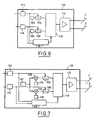
- a member is shown functional transmission 130 of a carrier frequency modulated according to two different predetermined modulations.
- This transmitting member 130 has numerous elements in common with the emission device represented on Figure 6. These common elements arranged so analog, are designated by the same reference numbers.
- This functional transmitting member 130 comprises a carrier frequency generator 132 as well as two different modulation signal generation devices 134.136.
- This carrier frequency generator 132 and these modulation signal generation devices 134, 136 are respectively connected to the inputs of means of modulation of the carrier frequency by the signals of modulation carrying respectively the references 138, 140, and whose respective outputs are connected to the inputs controllable connection means 106 and 108.
- a member is shown functional transmission of data frame 150 under the as a modulated signal.
- the elements common to the organs 100 and 130 described above, are designated by the same references.
- two memories of frames 152, 154 are connected to the inputs of the means of controllable connection 106, 108.
- the outputs of the means of controllable connection are connected to the inputs of a frame generation device 156 which is also connected the output of the device 118 for controlling consistency.
- the output of the frame generation device 156 is connected to the input of a modulator 158, one of which other input is connected to a frequency generator 160 carrier.
- modulator 158 The output of modulator 158 is connected to the input an emission unit 162 whose outputs are connected to supply conductors 2 and 3 of network 1.
- a receiving unit 164 whose inputs are connected to the supply conductors 2,3 of the network 1 a its output connected to the input of a demodulator 166 including one other input is connected to the carrier frequency generator 160, and the output of which is connected to the frame generation 156.
- the arrangement made by the receiving unit and the receiver is adapted to check the conformity of the transmission made by the transmitting unit 162 to network 1 and possibly pilot the generation of frame 156 so that it generates a new modulated frame transmission over the network.
- the communication system limits the consumption of electrical energy by disconnecting some of the devices from the functional organs correspondents.
- the means of testing the control means 52.70 include means of analyzing the activity rate of communication network 1.
- control means 52.70 control the control means 58.72 of the supply of the associated application equipment, to cut it so that consumption in electrical energy of the latter is decreased.
- control means 52 via control means 54 open the circuit powering the protocol management unit 42, and generate a sleep command signal that they transmit via command line 28 to the equipment application 12.
- Protocol management unit 42 and equipment application 12 being disconnected from the source electric power supply 4, consumption overall communication system is reduced.
- control means 52 control, in transmitting a wake-up command signal, the means of control 54 and 58 to restore power to the unit 42 protocol management and application equipment 12.
- the functional organ can again be used, and receive or transmit data via the network 1.
- control means 70 control the control means 54 and 72 in order to cause the opening of the power supply circuit of the management unit protocol 42 and the corresponding applicative member 32.
- control means 72 of the supply of the application equipment 32 are arranged on the supply line 74 supplying the output power supply 40 to which the equipment is connected application 32 via power line 36.
- the means test means 52 and 70 include means for detecting predetermined information of validation of predetermined criteria issued on supply conductors by at least one functional member, such as those shown diagrammatically in FIGS. 6 to 8.
- a device for controlling control of the supply (not shown) of certain application equipment when the vehicle is in a phase of operation allowing the disconnection of certain application equipment, a device for controlling control of the supply (not shown) of certain application equipment generates and transmits to control command detection means 114, a signal of standby leading to generation on the network, predetermined information that the means of validation test of predetermined criteria are adapted to evaluate.
- this control device control of the supply of certain application equipment can be an ignition key detector or a human presence detector in the vehicle interior.
- this information can take the form of an unmodulated carrier frequency (Figure 6), a modulated carrier frequency ( Figure 7) or a frame data in the form of a modulated signal (Figure 8).
- control means 52 and 70 depending on recognition of predetermined information on the network by test means, order as has been explained above, the means for controlling the power supply application equipment and associated protocol management.
- the detection means of piloting command 114 control the connection means 106 so that the carrier frequency generated by the carrier frequency generator 102 is routed to the transmission delay device 110.
- the consistency check device 118 does not does not detect any inconsistency between the signals received by the control command detection means 114 and 116, this controls the transmission timing device 110 to allow through the unit 112, transmission over the network for one carrier frequency predetermined time period f1.
- the body functional 100 transmits a second frequency over the network carrier f2 different from the first, generated by the carrier frequency generator 104.
- This second carrier frequency f2 is adapted to allow the restoration of the feeding of application equipment by their respective means of supply control.
- control device consistency 118 would detect an inconsistency between commands received by the command detection means 114, 116, it could be brought to prohibit any transmission by the timer 110 or, on the contrary, allow the emission of the carrier frequency f2 corresponding to the restoration application equipment power.
- the functional emission member 130 represented in Figure 7 is suitable for generating so selective in response to a specific control command detected by the control detection means control 114 or 116, a modulated carrier frequency, of which the specific modulation is defined by the generator modulation signal 134 or 136.
- receiving a command to control on one or other of the detection means control command 114, 116 causes the connection of a frame memories 152 or 154 with the frame generation 156.
- the device of frame generation 156 Insofar as the control device consistency 118 does not detect any inconsistency, the device of frame generation 156 generates a frame of data whose data field is stored in the memory of frame with which it is connected. This frame of data is routed to modulator 158 which, thanks to the carrier frequency generated by the frequency generator carrier 160 generates towards the entrance of the unit 162, a modulated carrier frequency whose modulation is representative of the information contained in the data field of the frame generated by the frame generation device 156.
- the transmitting unit 162 conventionally transmits on network 1 the modulated carrier frequency.
- Frame generator 156 monitors compliance of the transmission made by the transmitting unit 162 by checking the data received from the demodulator 166, which receives a modulated signal from the receiving unit 164 scanning the network.
Landscapes
- Engineering & Computer Science (AREA)
- Mechanical Engineering (AREA)
- Small-Scale Networks (AREA)
- Cable Transmission Systems, Equalization Of Radio And Reduction Of Echo (AREA)
Claims (10)
- System zur Datenübertragung mittels Trägerströmen, insbesondere für ein Automobil, mit einer elektrischen Energieversorgungsquelle, an der Versorgungsleitungen (2, 3) angeschlossen sind, welche ein Datenübertragungsnetzwerk (1) bilden und mit Funktionsorganen (6) des Fahrzeugs verbunden sind, von denen wenigstens einige zu einer gegenseitigen Datenübertragung ausgebildet sind, dadurch gekennzeichnet, daß wenigstens einige der Funktionsorgane (6) jeweils eine Datenübertragungsschnittstelle (10; 30) und ein zugeordnetes Anwendungsgerät (12, 32) aufweisen, das über seine Datenübertragungsschnittstelle (10; 30) mit anderen Funktionsorganen (6) Daten austauschen kann, wobei die Datenübertragungsschnittstelle (10; 30) eine Einrichtung zum Prüfen der Erfüllung wenigstens eines vorgegebenen Kriteriums und eine Steuereinrichtung (52; 70) für ein Stellglied (58; 72) der Stromversorgung des zugeordneten Anwendungsgeräts (12; 32) aufweist, um in Abhängigkeit von der Erfüllung des vorgegebenen Kriteriums zu veranlassen, daß das zugeordnete Anwendungsgerät (12; 32) aus den Versorgungsleitungen (2, 3) versorgt wird oder nicht.
- Datenübertragungssystem nach Anspruch 1, dadurch gekennzeichnet, daß das Stellglied (58) für die Stromversorgung des Anwendungsgeräts (12) im Anwendungsgerät (12) eingebaut ist und als Eingangssignal Steuerdaten aus der in der Datenübertragungsschnittstelle (10) angeordneten Steuereinrichtung (52) über eine Steuerleitung (28) empfängt, um das zugeordnete Anwendungsgerät (12) aus den Versorgungsleitungen (2, 3) über den Stellgliedausgang zu versorgen oder nicht.
- Datenübertragungssystem nach Anspruch 1, dadurch gekennzeichnet, daß das Stellglied (72) für die Stromversorgung des Anwendungsgeräts (32) in der Datenübertragungsschnittstelle (30) eingebaut ist und als Eingangssignal Steuerdaten aus der Steuereinrichtung (70) empfängt, um das zugeordnete Anwendungsgerät (12) aus den Versorgungsleitungen (2, 3) über den Stellgliedausgang und eine Gerätestromleitung (36) zu versorgen oder nicht.
- Datenübertragungssystem nach einem der vorangehenden Ansprüche, dadurch gekennzeichnet, daß die Datenübertragungsschnittstelle (10; 30) eine Protokollsteuerungseinrichtung (42) und ein Stellglied (54) für die Versorgung der Protokollsteuerungseinrichtung (42) aufweist, das durch die Steuereinrichtung (52; 70) in Abhängigkeit von der Erfüllung des vorgegebenen Kriteriums gesteuert wird, um die Protokollsteuerungseinrichtung (42) zu versorgen oder nicht.
- Datenübertragungssystem nach einem der vorangehenden Ansprüche, dadurch gekennzeichnet, daß die Einrichtung zum Prüfen der Erfüllung des vorgegebenen Kriteriums ferner ausgebildet ist, vorgegebene Daten der Erfüllung des Kriteriums zu erfassen, die von wenigstens einem Funktionsorgan (100; 130; 150) in das Netzwerk gesendet werden.
- Datenübertragungssystem nach Anspruch 5, dadurch gekennzeichnet, daß die vorgegebenen Daten durch wenigstens ein Signal vorgegebener Trägerfrequenz gebildet sind.
- Datenübertragungssystem nach Anspruch 6, dadurch gekennzeichnet, daß einige Funktionsorgane (100; 130) eingerichtet sind, wenigstens ein Signal vorgegebener Trägerfrequenz in das Netzwerk (1) zu senden.
- Datenübertragungssystem nach Anspruch 5, dadurch gekennzeichnet, daß die vorgegebenen Daten durch wenigstens eine Folge vorgegebener Daten gebildet sind.
- Datenübertragungssystem nach Anspruch 8, dadurch gekennzeichnet, daß einige Funktionsorgane (150) eingerichtet sind, wenigstens eine Folge vorgegebener Daten in das Netzwerk (1) zu senden.
- Datenübertragungssystem nach einem der Ansprüche 1 bis 4, dadurch gekennzeichnet, daß die Einrichtung zum Prüfen der Erfüllung des vorgegebenen Kriteriums ferner ausgebildet ist, den Aktivitätsgrad des Datenübertragungsnetzwerks (1) zu analysieren.
Applications Claiming Priority (2)
| Application Number | Priority Date | Filing Date | Title |
|---|---|---|---|
| FR9412831 | 1994-10-26 | ||
| FR9412831A FR2726411B1 (fr) | 1994-10-26 | 1994-10-26 | Systeme de communication d'informations par courants porteurs, notamment pour un vehicule automobile |
Publications (2)
| Publication Number | Publication Date |
|---|---|
| EP0709254A1 EP0709254A1 (de) | 1996-05-01 |
| EP0709254B1 true EP0709254B1 (de) | 1998-01-14 |
Family
ID=9468249
Family Applications (1)
| Application Number | Title | Priority Date | Filing Date |
|---|---|---|---|
| EP95402332A Expired - Lifetime EP0709254B1 (de) | 1994-10-26 | 1995-10-19 | Elektronisches Informationsübertragungssystem auf stromführenden Leitungen, insbesonders für ein Kraftfahrzeug |
Country Status (5)
| Country | Link |
|---|---|
| US (1) | US5745027A (de) |
| EP (1) | EP0709254B1 (de) |
| JP (1) | JPH08213941A (de) |
| DE (1) | DE69501453T2 (de) |
| FR (1) | FR2726411B1 (de) |
Cited By (1)
| Publication number | Priority date | Publication date | Assignee | Title |
|---|---|---|---|---|
| TWI549842B (zh) * | 2010-04-30 | 2016-09-21 | 能量匯流排協會 | 模組化車輛系統、電動車、模組及安全連接模組與電動車之方法 |
Families Citing this family (74)
| Publication number | Priority date | Publication date | Assignee | Title |
|---|---|---|---|---|
| US6733036B2 (en) | 1995-06-07 | 2004-05-11 | Automotive Technologies International, Inc. | Automotive electronic safety network |
| US6533316B2 (en) | 1995-06-07 | 2003-03-18 | Automotive Technologies International, Inc. | Automotive electronic safety network |
| US6326704B1 (en) * | 1995-06-07 | 2001-12-04 | Automotive Technologies International Inc. | Vehicle electrical system |
| US6648367B2 (en) | 1995-06-07 | 2003-11-18 | Automotive Technologies International Inc. | Integrated occupant protection system |
| US8036788B2 (en) * | 1995-06-07 | 2011-10-11 | Automotive Technologies International, Inc. | Vehicle diagnostic or prognostic message transmission systems and methods |
| US9443358B2 (en) | 1995-06-07 | 2016-09-13 | Automotive Vehicular Sciences LLC | Vehicle software upgrade techniques |
| US7580782B2 (en) * | 1995-10-30 | 2009-08-25 | Automotive Technologies International, Inc. | Vehicular electronic system with crash sensors and occupant protection systems |
| US7744122B2 (en) | 1995-12-12 | 2010-06-29 | Automotive Technologies International, Inc. | Driver side aspirated airbags |
| DE19622529A1 (de) * | 1996-06-05 | 1997-12-11 | Mannesmann Vdo Ag | Ansteuereinrichtung |
| JP3351264B2 (ja) * | 1996-10-16 | 2002-11-25 | 株式会社豊田自動織機 | 移動体の給電線重畳通信システム |
| DE19733866C2 (de) | 1997-08-05 | 2002-09-12 | Siemens Ag | System zur Übertragung von Daten in einem Kraftfahrzeug |
| US6069581A (en) | 1998-02-20 | 2000-05-30 | Amerigon | High performance vehicle radar system |
| WO1999042856A2 (en) * | 1998-02-19 | 1999-08-26 | Amerigon Inc. | High performance vehicle radar system |
| US6380883B1 (en) | 1998-02-23 | 2002-04-30 | Amerigon | High performance vehicle radar system |
| US6400308B1 (en) | 1998-02-20 | 2002-06-04 | Amerigon Inc. | High performance vehicle radar system |
| DE19813943A1 (de) * | 1998-03-28 | 1999-09-30 | Telefunken Microelectron | Vorrichtung zur Ansteuerung von Rückhalteeinrichtungen in einem Fahrzeug |
| FR2784635B1 (fr) * | 1998-10-15 | 2000-12-29 | Framatome Connectors Int | Dispositif de cablage pour vehicules a moteur ou similaires |
| US10240935B2 (en) | 1998-10-22 | 2019-03-26 | American Vehicular Sciences Llc | Vehicle software upgrade techniques |
| DE19935893B4 (de) * | 1999-07-30 | 2004-01-29 | Robert Bosch Gmbh | Fahrzeugelektronik |
| US6842459B1 (en) | 2000-04-19 | 2005-01-11 | Serconet Ltd. | Network combining wired and non-wired segments |
| US6765495B1 (en) | 2000-06-07 | 2004-07-20 | Hrl Laboratories, Llc | Inter vehicle communication system |
| US6800957B2 (en) * | 2001-02-06 | 2004-10-05 | General Electric Company | Electronic distribution system for 36V automobiles |
| US20030018840A1 (en) * | 2001-07-18 | 2003-01-23 | Chandler Billy J. | Power bus information transmission system and method of data transmission |
| JP2003046453A (ja) * | 2001-07-31 | 2003-02-14 | Denso Corp | 電源ic |
| DE10142409A1 (de) * | 2001-08-31 | 2003-04-17 | Bosch Gmbh Robert | Versorgungsleitungsstruktur zur Übertragung von Informationen zwischen Kraftfahrzeugkomponenten |
| TW530798U (en) * | 2001-11-14 | 2003-05-01 | Wintecronics Ltd | Anti-theft system for vehicle |
| DE10248821A1 (de) * | 2002-10-19 | 2004-04-29 | Robert Bosch Gmbh | Versorgungsleitungsstruktur |
| JP3889717B2 (ja) * | 2003-02-28 | 2007-03-07 | 矢崎総業株式会社 | 光通信システムの信号中継装置 |
| FR2853171A1 (fr) * | 2003-03-24 | 2004-10-01 | Peugeot Citroen Automobiles Sa | Routage des liaisons electriques entre appareils electriques equipant un vehicule de transport. |
| US6906618B2 (en) * | 2003-06-26 | 2005-06-14 | Abet Technologies, Llc | Method and system for bidirectional data and power transmission |
| FR2861930B1 (fr) * | 2003-11-05 | 2006-02-03 | Dassault Aviat | Dispositif d'echange d'informations |
| DE102004026468A1 (de) * | 2004-05-29 | 2005-12-22 | Daimlerchrysler Ag | Datenübertragung auf Stromversorgungsleitungen |
| FR2871967B1 (fr) * | 2004-06-18 | 2006-09-22 | Valeo Electronique Sys Liaison | Module d'echange d'informations par courants porteurs et procede de gestion du fonctionnement de ce module |
| WO2006028923A2 (en) * | 2004-09-01 | 2006-03-16 | Abet Technologies, Llc | Method and system for bidirectional communications and power transmission |
| US7859397B2 (en) * | 2004-09-17 | 2010-12-28 | Keith Lamon | Systems and methods for direct current system digital carried message conveyance |
| US8638216B2 (en) | 2004-09-17 | 2014-01-28 | Keith Lamon | Systems and methods for direct current system digital carried message conveyance |
| US7307520B2 (en) * | 2004-09-17 | 2007-12-11 | Keith Lamon | Systems and methods for direct current system digital carried message conveyance |
| US7405652B2 (en) * | 2004-09-21 | 2008-07-29 | Abet Technologies, Llc | Communication and AC power system |
| US8089345B2 (en) * | 2004-11-10 | 2012-01-03 | Caterpillar Inc. | System and method for power and data delivery on a machine |
| US20060097852A1 (en) * | 2004-11-10 | 2006-05-11 | Lammers Bryan G | System and method for power and data delivery on a machine |
| US20100207744A1 (en) * | 2004-11-10 | 2010-08-19 | Caterpillar Inc. | System And Method For Power And Data Delivery On A Machine |
| US8405500B2 (en) * | 2004-11-10 | 2013-03-26 | Caterpillar Inc. | System and method for power and data delivery on a machine |
| MX2007009154A (es) * | 2005-01-31 | 2007-10-08 | Abet Technologies Llc | Sistema de computo seguro. |
| US7352281B2 (en) * | 2005-02-22 | 2008-04-01 | Instrument Systems Inc. | Automotive gauge system using a power line carrier |
| CN101171153B (zh) * | 2005-05-11 | 2010-05-12 | 株式会社日立制作所 | 汽车及汽车内的通信与控制装置 |
| US7307519B2 (en) * | 2005-07-12 | 2007-12-11 | Yazaki Corporation | Communication system and PLC network |
| US7352282B2 (en) * | 2005-07-12 | 2008-04-01 | Yazaki Corporation | Communication system |
| JP4717569B2 (ja) * | 2005-09-15 | 2011-07-06 | 川崎重工業株式会社 | 自動二輪車 |
| US20080143492A1 (en) * | 2006-12-15 | 2008-06-19 | Ford Global Technologies, Llc | Power line communication (plc) system |
| US8303337B2 (en) | 2007-06-06 | 2012-11-06 | Veedims, Llc | Hybrid cable for conveying data and power |
| US7940673B2 (en) | 2007-06-06 | 2011-05-10 | Veedims, Llc | System for integrating a plurality of modules using a power/data backbone network |
| US7740501B2 (en) * | 2007-06-06 | 2010-06-22 | Claudio R. Ballard | Hybrid cable for conveying data and power |
| US20090136293A1 (en) * | 2007-11-28 | 2009-05-28 | Caterpillar S.A.R.L. | Two wire signal over power work tool coupling and identification |
| US20090223318A1 (en) * | 2008-03-06 | 2009-09-10 | Ballard Claudio R | Gear shift assembly |
| US20090223437A1 (en) * | 2008-03-07 | 2009-09-10 | Ballard Claudio R | Gauge having synthetic sapphire lens |
| US8111145B2 (en) * | 2008-03-07 | 2012-02-07 | Veedims, Llc | Starter control and indicator system |
| US7856158B2 (en) | 2008-03-07 | 2010-12-21 | Ballard Claudio R | Virtual electronic switch system |
| USD638033S1 (en) | 2008-03-07 | 2011-05-17 | Ballard Claudio R | Air intake assembly |
| EP2300255A2 (de) * | 2008-05-12 | 2011-03-30 | Veedims, LLC | Elektrisch angetriebenes fahrzeug mit elektrischem geräuscherzeugenden gebläse/kühler |
| EP2344360A1 (de) * | 2008-09-30 | 2011-07-20 | Veedims, LLC | System und verfahren zur handhabung einer verteilten autoaufladung |
| USD662869S1 (en) | 2010-06-01 | 2012-07-03 | Ballard Claudio R | Automotive wheel center nut |
| US10445962B2 (en) | 2011-02-07 | 2019-10-15 | Energybus E.V. | Modular vehicle system, electric vehicle, and module for connection to an electric vehicle |
| US8793096B2 (en) * | 2011-06-24 | 2014-07-29 | Caterpillar Inc. | System and method for power and data delivery on a machine |
| US8976541B2 (en) | 2011-08-31 | 2015-03-10 | Potens Ip Holdings Llc | Electrical power and data distribution apparatus |
| DE102014206514A1 (de) * | 2014-04-04 | 2015-10-08 | Comworks Gmbh | Reisemobil mit Datenbus |
| US10348418B1 (en) | 2014-07-22 | 2019-07-09 | Esker Technologies, LLC | Transient and spurious signal filter |
| US10417143B2 (en) | 2015-10-08 | 2019-09-17 | Esker Technologies, LLC | Apparatus and method for sending power over synchronous serial communication wiring |
| DE102015221201A1 (de) * | 2015-10-29 | 2017-05-04 | Bayerische Motoren Werke Aktiengesellschaft | Vorrichtung und System für ein Fahrzeugbordnetz mit einer ersten Versorgungsspannung und einer zweiten Versorgungsspannung |
| US10128906B2 (en) | 2016-07-11 | 2018-11-13 | Esker Technologies, LLC | Power line signal coupler |
| US10560154B2 (en) | 2016-07-11 | 2020-02-11 | Esker Technologies, LLC | Power line signal coupler |
| JP6593550B2 (ja) * | 2016-11-10 | 2019-10-23 | 株式会社オートネットワーク技術研究所 | 車載通信システム |
| CN111065549A (zh) * | 2017-04-27 | 2020-04-24 | 国际智能技术公司 | 车辆线束 |
| BE1026229B1 (nl) * | 2018-03-05 | 2019-11-26 | Jan Callewaert | Netwerk voor elektrische energie- en computerdatatransport |
| CN110562159B (zh) * | 2018-06-05 | 2021-11-19 | 郑州宇通客车股份有限公司 | 一种车载通信系统及新能源车辆 |
Family Cites Families (6)
| Publication number | Priority date | Publication date | Assignee | Title |
|---|---|---|---|---|
| DE2936929A1 (de) * | 1979-09-12 | 1981-04-02 | Sachs Systemtechnik Gmbh, 8720 Schweinfurt | Energieversorgungsanlage fuer kraftfahrzeuge |
| US4463341A (en) * | 1981-06-01 | 1984-07-31 | Aisin Seiki Kabushiki Kaisha | Single conductor multi-frequency electric wiring system for vehicles |
| US4907222A (en) * | 1988-08-17 | 1990-03-06 | Nuvatec, Inc. | Vehicle multiplex system |
| DE3912439A1 (de) * | 1989-04-15 | 1990-10-18 | Vdo Schindling | Signaluebertragungssystem |
| FR2661572B1 (fr) * | 1990-04-27 | 1992-07-03 | Renault | Dispositif de detection d'impulsions de courant. |
| JP2857501B2 (ja) * | 1991-02-18 | 1999-02-17 | マツダ株式会社 | 多重伝送装置 |
-
1994
- 1994-10-26 FR FR9412831A patent/FR2726411B1/fr not_active Expired - Fee Related
-
1995
- 1995-10-19 EP EP95402332A patent/EP0709254B1/de not_active Expired - Lifetime
- 1995-10-19 DE DE69501453T patent/DE69501453T2/de not_active Expired - Fee Related
- 1995-10-23 US US08/546,714 patent/US5745027A/en not_active Expired - Lifetime
- 1995-10-26 JP JP7278850A patent/JPH08213941A/ja not_active Withdrawn
Cited By (1)
| Publication number | Priority date | Publication date | Assignee | Title |
|---|---|---|---|---|
| TWI549842B (zh) * | 2010-04-30 | 2016-09-21 | 能量匯流排協會 | 模組化車輛系統、電動車、模組及安全連接模組與電動車之方法 |
Also Published As
| Publication number | Publication date |
|---|---|
| US5745027A (en) | 1998-04-28 |
| JPH08213941A (ja) | 1996-08-20 |
| DE69501453D1 (de) | 1998-02-19 |
| FR2726411B1 (fr) | 1997-01-17 |
| FR2726411A1 (fr) | 1996-05-03 |
| DE69501453T2 (de) | 1998-06-18 |
| EP0709254A1 (de) | 1996-05-01 |
Similar Documents
| Publication | Publication Date | Title |
|---|---|---|
| EP0709254B1 (de) | Elektronisches Informationsübertragungssystem auf stromführenden Leitungen, insbesonders für ein Kraftfahrzeug | |
| FR2512298A1 (fr) | Systeme et methode de modulation de frequence optique | |
| EP0034957A1 (de) | Vorrichtung zur automatischen Regulierung der Ausgangsleistung eines Sendermoduls für ein Übertragungssystem mit optischen Fasern | |
| FR2740264A1 (fr) | Dispositif de gestion de batteries electriques | |
| EP0034082B1 (de) | Vorrichtung zur Alarmauslösung im Falle eines ungenügenden Übertragungspegels für den Empfängermodul eines Übertragungssystems mit optischen Fasern | |
| FR2750276A1 (fr) | Procede de commande de transfert d'informations entre les composants ainsi que composants pour la mise en oeuvre du procede | |
| EP0566464B1 (de) | Quelle für optische Pulse und optisches Solitonübertragungssystem mit dieser Quelle | |
| EP3248305B1 (de) | Ethernet-switch für faseroptisches netzwerk | |
| EP0027413A1 (de) | Übertragungssystem mit gleichzeitigem integralen Vielfachzugriff über optische Fiberübertragungsleitungen | |
| EP0356334B1 (de) | System zur gegenseitigen Informationsübertragung zwischen einem tragbaren Gegenstand, insbesondere einem Schlüssel, und einem anderen Datenträger | |
| CH637779A5 (fr) | Detecteur photoelectrique. | |
| EP0843931B1 (de) | Übertragungsverfahren über einen optischen bus mit gleichzeitig verschiedenen datenraten | |
| EP0370862A1 (de) | Verfahren und System zur Signalübertragung | |
| EP0496676B1 (de) | Verfahren und Vorrichtung zur Positionierung von Frequenzen, insbesondere optischen | |
| FR2859856A1 (fr) | Systeme et disposiif d'alimentation a distance d'un equipement de traitement d'informations | |
| EP0823154B1 (de) | Verfahren und einrichtung zur übertragung analoger signale mittels eines übertragungssystems mit optischen übertragungsleitungen | |
| FR2496257A1 (fr) | Procede et installation de lecture automatique a courte distance d'informations numeriques representant une consommation, notamment d'energie electrique | |
| EP1317162A2 (de) | Rückgrat Schnittstelle, Endgerät Schnittstelle für Raumfahrzeug und Kommunikationsnetz mit solcher Schnittstellen | |
| EP0230406A1 (de) | Einrichtung zur gleichzeitigen übertragung mehrerer elektrischer signale zwischen zwei orten | |
| EP0711685B1 (de) | Elektrische Verbindung zwischen den Bauteilen im Lenkrad mit den Bauteilen in der Karrosserie eines Kraftfahrzeuges | |
| FR2763184A1 (fr) | Dispositif de validation de messages numeriques, applicable notamment aux systemes de regulation du trafic ferroviaire | |
| EP0717531A1 (de) | Datenübertragungsschaltung auf einem Stromnetz mit niedrigen Empfängerschwellwert | |
| FR2524230A1 (fr) | Systeme de transmission d'informations sur une voie de service du type fibre optique | |
| EP0918418B1 (de) | System zur Informationsübertragung zwischen durch ein Multiplexnetzwerk, angeschlossenen Stationen insbesondere für Kraftfahrzeuge | |
| FR3127054A1 (fr) | Architecture de réveil et d’endormissement de calculateurs compatible avec différents types de véhicules automobiles |
Legal Events
| Date | Code | Title | Description |
|---|---|---|---|
| PUAI | Public reference made under article 153(3) epc to a published international application that has entered the european phase |
Free format text: ORIGINAL CODE: 0009012 |
|
| AK | Designated contracting states |
Kind code of ref document: A1 Designated state(s): DE GB IT |
|
| 17P | Request for examination filed |
Effective date: 19960311 |
|
| GRAG | Despatch of communication of intention to grant |
Free format text: ORIGINAL CODE: EPIDOS AGRA |
|
| 17Q | First examination report despatched |
Effective date: 19970304 |
|
| GRAH | Despatch of communication of intention to grant a patent |
Free format text: ORIGINAL CODE: EPIDOS IGRA |
|
| GRAH | Despatch of communication of intention to grant a patent |
Free format text: ORIGINAL CODE: EPIDOS IGRA |
|
| GRAA | (expected) grant |
Free format text: ORIGINAL CODE: 0009210 |
|
| AK | Designated contracting states |
Kind code of ref document: B1 Designated state(s): DE GB IT |
|
| ITF | It: translation for a ep patent filed | ||
| GBT | Gb: translation of ep patent filed (gb section 77(6)(a)/1977) |
Effective date: 19980116 |
|
| REF | Corresponds to: |
Ref document number: 69501453 Country of ref document: DE Date of ref document: 19980219 |
|
| PLBE | No opposition filed within time limit |
Free format text: ORIGINAL CODE: 0009261 |
|
| STAA | Information on the status of an ep patent application or granted ep patent |
Free format text: STATUS: NO OPPOSITION FILED WITHIN TIME LIMIT |
|
| 26N | No opposition filed | ||
| PGFP | Annual fee paid to national office [announced via postgrant information from national office to epo] |
Ref country code: DE Payment date: 20011010 Year of fee payment: 7 |
|
| PGFP | Annual fee paid to national office [announced via postgrant information from national office to epo] |
Ref country code: GB Payment date: 20011012 Year of fee payment: 7 |
|
| REG | Reference to a national code |
Ref country code: GB Ref legal event code: IF02 |
|
| PG25 | Lapsed in a contracting state [announced via postgrant information from national office to epo] |
Ref country code: GB Free format text: LAPSE BECAUSE OF NON-PAYMENT OF DUE FEES Effective date: 20021019 |
|
| PG25 | Lapsed in a contracting state [announced via postgrant information from national office to epo] |
Ref country code: DE Free format text: LAPSE BECAUSE OF NON-PAYMENT OF DUE FEES Effective date: 20030501 |
|
| GBPC | Gb: european patent ceased through non-payment of renewal fee |
Effective date: 20021019 |
|
| PG25 | Lapsed in a contracting state [announced via postgrant information from national office to epo] |
Ref country code: IT Free format text: LAPSE BECAUSE OF NON-PAYMENT OF DUE FEES Effective date: 20051019 |