EP0708317B2 - Schnelles bichromatisches fiberoptisches Pyrometer - Google Patents
Schnelles bichromatisches fiberoptisches Pyrometer Download PDFInfo
- Publication number
- EP0708317B2 EP0708317B2 EP95402286A EP95402286A EP0708317B2 EP 0708317 B2 EP0708317 B2 EP 0708317B2 EP 95402286 A EP95402286 A EP 95402286A EP 95402286 A EP95402286 A EP 95402286A EP 0708317 B2 EP0708317 B2 EP 0708317B2
- Authority
- EP
- European Patent Office
- Prior art keywords
- fast
- radiation
- temperature
- circuit
- bichromatic
- Prior art date
- Legal status (The legal status is an assumption and is not a legal conclusion. Google has not performed a legal analysis and makes no representation as to the accuracy of the status listed.)
- Expired - Lifetime
Links
Images


Classifications
-
- G—PHYSICS
- G01—MEASURING; TESTING
- G01J—MEASUREMENT OF INTENSITY, VELOCITY, SPECTRAL CONTENT, POLARISATION, PHASE OR PULSE CHARACTERISTICS OF INFRARED, VISIBLE OR ULTRAVIOLET LIGHT; COLORIMETRY; RADIATION PYROMETRY
- G01J5/00—Radiation pyrometry, e.g. infrared or optical thermometry
- G01J5/02—Constructional details
- G01J5/04—Casings
-
- G—PHYSICS
- G01—MEASURING; TESTING
- G01J—MEASUREMENT OF INTENSITY, VELOCITY, SPECTRAL CONTENT, POLARISATION, PHASE OR PULSE CHARACTERISTICS OF INFRARED, VISIBLE OR ULTRAVIOLET LIGHT; COLORIMETRY; RADIATION PYROMETRY
- G01J5/00—Radiation pyrometry, e.g. infrared or optical thermometry
- G01J5/0014—Radiation pyrometry, e.g. infrared or optical thermometry for sensing the radiation from gases, flames
-
- G—PHYSICS
- G01—MEASURING; TESTING
- G01J—MEASUREMENT OF INTENSITY, VELOCITY, SPECTRAL CONTENT, POLARISATION, PHASE OR PULSE CHARACTERISTICS OF INFRARED, VISIBLE OR ULTRAVIOLET LIGHT; COLORIMETRY; RADIATION PYROMETRY
- G01J5/00—Radiation pyrometry, e.g. infrared or optical thermometry
- G01J5/0022—Radiation pyrometry, e.g. infrared or optical thermometry for sensing the radiation of moving bodies
-
- G—PHYSICS
- G01—MEASURING; TESTING
- G01J—MEASUREMENT OF INTENSITY, VELOCITY, SPECTRAL CONTENT, POLARISATION, PHASE OR PULSE CHARACTERISTICS OF INFRARED, VISIBLE OR ULTRAVIOLET LIGHT; COLORIMETRY; RADIATION PYROMETRY
- G01J5/00—Radiation pyrometry, e.g. infrared or optical thermometry
- G01J5/0088—Radiation pyrometry, e.g. infrared or optical thermometry in turbines
-
- G—PHYSICS
- G01—MEASURING; TESTING
- G01J—MEASUREMENT OF INTENSITY, VELOCITY, SPECTRAL CONTENT, POLARISATION, PHASE OR PULSE CHARACTERISTICS OF INFRARED, VISIBLE OR ULTRAVIOLET LIGHT; COLORIMETRY; RADIATION PYROMETRY
- G01J5/00—Radiation pyrometry, e.g. infrared or optical thermometry
- G01J5/02—Constructional details
- G01J5/0215—Compact construction
-
- G—PHYSICS
- G01—MEASURING; TESTING
- G01J—MEASUREMENT OF INTENSITY, VELOCITY, SPECTRAL CONTENT, POLARISATION, PHASE OR PULSE CHARACTERISTICS OF INFRARED, VISIBLE OR ULTRAVIOLET LIGHT; COLORIMETRY; RADIATION PYROMETRY
- G01J5/00—Radiation pyrometry, e.g. infrared or optical thermometry
- G01J5/02—Constructional details
- G01J5/026—Control of working procedures of a pyrometer, other than calibration; Bandwidth calculation; Gain control
-
- G—PHYSICS
- G01—MEASURING; TESTING
- G01J—MEASUREMENT OF INTENSITY, VELOCITY, SPECTRAL CONTENT, POLARISATION, PHASE OR PULSE CHARACTERISTICS OF INFRARED, VISIBLE OR ULTRAVIOLET LIGHT; COLORIMETRY; RADIATION PYROMETRY
- G01J5/00—Radiation pyrometry, e.g. infrared or optical thermometry
- G01J5/02—Constructional details
- G01J5/04—Casings
- G01J5/048—Protective parts
-
- G—PHYSICS
- G01—MEASURING; TESTING
- G01J—MEASUREMENT OF INTENSITY, VELOCITY, SPECTRAL CONTENT, POLARISATION, PHASE OR PULSE CHARACTERISTICS OF INFRARED, VISIBLE OR ULTRAVIOLET LIGHT; COLORIMETRY; RADIATION PYROMETRY
- G01J5/00—Radiation pyrometry, e.g. infrared or optical thermometry
- G01J5/02—Constructional details
- G01J5/08—Optical arrangements
- G01J5/0801—Means for wavelength selection or discrimination
-
- G—PHYSICS
- G01—MEASURING; TESTING
- G01J—MEASUREMENT OF INTENSITY, VELOCITY, SPECTRAL CONTENT, POLARISATION, PHASE OR PULSE CHARACTERISTICS OF INFRARED, VISIBLE OR ULTRAVIOLET LIGHT; COLORIMETRY; RADIATION PYROMETRY
- G01J5/00—Radiation pyrometry, e.g. infrared or optical thermometry
- G01J5/02—Constructional details
- G01J5/08—Optical arrangements
- G01J5/0806—Focusing or collimating elements, e.g. lenses or concave mirrors
-
- G—PHYSICS
- G01—MEASURING; TESTING
- G01J—MEASUREMENT OF INTENSITY, VELOCITY, SPECTRAL CONTENT, POLARISATION, PHASE OR PULSE CHARACTERISTICS OF INFRARED, VISIBLE OR ULTRAVIOLET LIGHT; COLORIMETRY; RADIATION PYROMETRY
- G01J5/00—Radiation pyrometry, e.g. infrared or optical thermometry
- G01J5/02—Constructional details
- G01J5/08—Optical arrangements
- G01J5/0813—Planar mirrors; Parallel phase plates
-
- G—PHYSICS
- G01—MEASURING; TESTING
- G01J—MEASUREMENT OF INTENSITY, VELOCITY, SPECTRAL CONTENT, POLARISATION, PHASE OR PULSE CHARACTERISTICS OF INFRARED, VISIBLE OR ULTRAVIOLET LIGHT; COLORIMETRY; RADIATION PYROMETRY
- G01J5/00—Radiation pyrometry, e.g. infrared or optical thermometry
- G01J5/02—Constructional details
- G01J5/08—Optical arrangements
- G01J5/0818—Waveguides
- G01J5/0821—Optical fibres
-
- G—PHYSICS
- G01—MEASURING; TESTING
- G01J—MEASUREMENT OF INTENSITY, VELOCITY, SPECTRAL CONTENT, POLARISATION, PHASE OR PULSE CHARACTERISTICS OF INFRARED, VISIBLE OR ULTRAVIOLET LIGHT; COLORIMETRY; RADIATION PYROMETRY
- G01J5/00—Radiation pyrometry, e.g. infrared or optical thermometry
- G01J5/02—Constructional details
- G01J5/08—Optical arrangements
- G01J5/0887—Integrating cavities mimicking black bodies, wherein the heat propagation between the black body and the measuring element does not occur within a solid; Use of bodies placed inside the fluid stream for measurement of the temperature of gases; Use of the reemission from a surface, e.g. reflective surface; Emissivity enhancement by multiple reflections
-
- G—PHYSICS
- G01—MEASURING; TESTING
- G01J—MEASUREMENT OF INTENSITY, VELOCITY, SPECTRAL CONTENT, POLARISATION, PHASE OR PULSE CHARACTERISTICS OF INFRARED, VISIBLE OR ULTRAVIOLET LIGHT; COLORIMETRY; RADIATION PYROMETRY
- G01J5/00—Radiation pyrometry, e.g. infrared or optical thermometry
- G01J5/60—Radiation pyrometry, e.g. infrared or optical thermometry using determination of colour temperature
- G01J5/602—Radiation pyrometry, e.g. infrared or optical thermometry using determination of colour temperature using selective, monochromatic or bandpass filtering
Definitions
- the present invention relates to a pyrometer for the realization of thermal diagnostics (measurement of gas temperatures or moving surfaces) in a severe environment, with a very high speed of measurement.
- Measurement errors related to optical transmission problems can notably exist in devices using a monochromatic optical fiber for capturing and transporting thermal radiation emitted by the moving turbine.
- a separator cube In bichromatic measurement devices in which it is necessary to proceed to the separation of the light beam at the output of the transport fiber, it is conventional to use a separator cube because it has a high homogeneity with the fiber.
- such a cube is particularly sensitive to vibrations and possible shocks and the distribution of the luminous flux at its output can then be modified.
- European demand EP-A-216458 an optical pyrometer using an optical fiber whose output light energy is divided into two elementary beams which limits both the response time and the resolution of such a pyrometer. More simply chromatic aberrations can appear when the fiber output beam is poorly collimated ( WO-A-91/03715 ).
- the processing of the signals from the separation means is generally performed in real time in an analog form using conventional discrete components. This results in significant response times (of the order of a millisecond) and, in the case of measurements at high frequencies, particularly important operating constraints.
- the stabilization of the measuring device imposes a limitation of the bandwidth and consequently of the overall rate (speed) of measurement.
- such a device remains sensitive to all phenomena of drift in voltage or temperature, the removal of which can then be considered only at the cost of frequent and tedious adjustments.
- the combination of the splitter cube optical system and the aforementioned analog electronic assembly does not make it possible to achieve a miniaturized device whose need is however present in particular in embedded systems where such a device would be useful for clarifying the limits of operation of turbine engines and in particular the control of their transient conditions.
- the present invention aims to overcome the aforementioned drawbacks and to provide a particularly compact pyrometer adapted to fast detection rates so that it can perform continuously, in a wide range of temperatures, instantaneous temperature measurements. in particular rotating turbine blades.
- the structure thus defined results in obtaining a particularly compact pyrometer, with the use of a dichroic blade as a separator device, and fast, by the use of a signal processor combined with a fast memory containing a conversion table. pre-established, in particular allowing the instantaneous measurement of the temperature of rotating turbine blades.
- the offset of the measurement is not essential and the measurement can be made directly from the optical block which will then be advantageously provided with means for focusing the radiation emitted by the surface.
- Measurements can be made from wide spectral bands to monochromatic domains where it is necessary for each of the separate radiation output focusing means to be preceded by interference filtering means.
- the focusing means comprise achromatic doubles.
- the fast conversion means advantageously comprise two analog-to-digital converters of the flash type.
- the means for adapting the amplification level comprise, preferably for each signal Vr or Vb, a multiplexer circuit a pathway to at least two channels receiving the signal and delivering it to one of at least two amplification circuits. different gain whose outputs are connected to a demultiplexer circuit of at least two channels to a channel, only one of the amplification circuits being selected at each calculation of the Vr / Vb ratio.
- the processing circuit may also include digital-to-analog conversion means placed at the output of the signal processor and intended to obtain an analog value of the measured temperature.
- the detection circuit comprises two quantic detectors of the InGaAs type. These detectors transform the radiation they receive into an electric current proportional to the power of this radiation.
- the storage means comprise a flash-type fast memory which is well adapted to a DSP-type processor.
- the measuring probe comprises a sapphire bar covered with a thin protective layer and whose end facing the fiber has a spherical cap focusing in the fiber almost all radiation emitted.
- the other end of the measuring probe receiving the radiation may comprise a hemispherical cap whose radius is determined according to the distance to the surface.
- the end of the measuring probe is covered with a coating conferring a thermal emission of black body type.
- This coating consists of a first highly emissive layer, and a second layer opaque to light and strongly conductive. It can also be provided with an intermediate layer placed between the first and second layers and ensuring optimization of the heat diffusion and homogenization of the temperature. If these layers optimize the emission and the heat transfer, they also make it possible to ensure the thermomechanical and chemical resistance of the probe according to its environment (reducing or oxidizing medium).
- the pyrometer of the invention is schematically illustrated on the figure 1 . It comprises an optical sensor or sensor 1 placed opposite a hot body, or in a gaseous medium, whose temperature is to be measured and which is connected to an optical block 2 via a single optical fiber 3.
- a detection circuit placed at the output of the optical block, or preferably integrated in this block, allows a conversion of the optical signals that it delivers into exploitable electrical signals by a processing unit 5 (after possibly conversion and adaptation by a conversion circuit 4) which then generates the value of the desired temperature.
- the configuration of the pyrometer presented is bichromatic, that is to say that the thermal radiation emitted by the surface of the hot body or the gas (the measuring probe then comprising a coating acting as a black micro-body) is measured on two spectral bands. distinct. It is thus possible to limit the causes of errors corresponding to the losses in transmissions and coupling of the radiation (curvatures, connectors, soiling) which directly affect the measurement in the case of a monochromatic analysis.
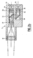
- a bichromatic structure requires separating the radiation coming out of the fiber in two parts. This is the object of the block optics 2 whose material structure is now described more precisely with regard to the figure 2a .
- This optical unit 2 comprises input input collimation means 20 for transmitting the radiation from the fiber 3 parallel to means for separating this beam into two parts constituted by a dichroic plate 22 which also acts as a filter transmission high pass and low pass in reflection. The beams leaving this plate are then directed, directly or via a mirror 28, to spectral selection means (red and blue spectra) comprising interference filters 30, 32. Output focusing means 24, 26 placed at the output of these filters make it possible to concentrate the separated radiations on quantum detectors 33, 34, preferably with gallium indium arsenide (In Ga As). The optical block thus produced is particularly compact and has high performance.
- the signal levels available at the input of the quantum detectors are higher than the signal levels that could be collected at the output of a separator cube and, secondly, the dichroic plate is not sensitive. to polarization and does not introduce aberrations in the event of possible poor convergence of the radiation.
- the gain on each of the luminous flux leaving the blade, relative to a device with separator cube, is 100%. It is thus possible either to use a fiber of smaller diameter for the measurement of the same temperature, or to extend the temperature range measured especially to low temperatures. It may be noted that in the case of spectral broadband measurements (300 to 400 nanometers), the interference filters 30, 32 may advantageously be omitted. It may also be noted that the use of achromatic optical doublets at the level of the focusing means also makes it possible to obtain an optimum spatial resolution allowing the use of detectors with a small surface area.
- the figure 2b shows a second embodiment of the optical block.
- the measurement can be performed directly from the optical unit 2 by providing it with means allowing a pyrometric aiming.
- These means comprise input focusing means 18 which capture the radiation and focus it at the focal point of the input collimating means 20, the light flux then going, as before, towards the separation means 22 and leading to the detectors 33. , 34.
- the electric currents delivered by the photovoltaic detectors are transformed into voltage and normalized in the current-voltage conversion circuit 4 which, for reasons of improvement of the signal / noise ratio, can advantageously be integrated into the optical unit.
- Vr red voltage
- Vb blue voltage
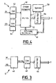
- this circuit comprises a simplified architecture both analog and digital particularly suitable for low measurement rates (of the order of 1000 measurements per second).
- this processing circuit comprises an entirely digital architecture organized around a digital microprocessor computing assembly 50 which receives the voltages Vr and Vb from the detectors and digitized by analog-to-digital converters 52, 54 and which delivers, after calculation, a value digital equal to the ratio Vr / Vb for storage means 56 which is extracted directly, as previously, the measured temperature T.
- a synchronization module 58 connected to the calculation unit 50 ensures the triggering of the measurement process under the control of a control software. management stored in a read-only memory 60 advantageously programmable and erasable (EPROM).
- EPROM programmable and erasable
- a display module 62 allows the display of the temperature T but also that of the ratio Vr / Vb.
- the converters have a resolution of 16 bits and have conversion times of the order of one microsecond.
- the ratio Vr / Vb is calculated in real time by the digital calculation unit 50 and is used as a pointer to extract the value of the temperature of the storage means which comprises as before a table of values (conversion table) giving the temperature T for each Vr / Vb ratio.
- Vr and Vb being the two color voltages (red and blue) delivered by the detectors and A and B two constants determined by a prior calibration.
- the signals Vr and Vb evolve in very important proportions whereas the ratio Vr / Vb remains on the contrary included in a rather reduced field which it is easy to cover entirely with a conversion table of reasonable size.
- a table having the input variable Vr / Vb as the input variable and the temperature output variable as an output variable are obtained. T and can be stored in a memory of 2048 words.
- the calculation of the ratio Vr / Vb is carried out at the level of the computing unit 50 which advantageously comprises a circuit specialized in the processing of the digital signals such as a signal processor (Digital Signal Processor) for example, which makes it possible to carry out operations on 48 or even 56 bits.
- a signal processor Digital Signal Processor
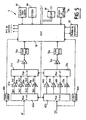
- the figure 5 shows a preferred embodiment of the processing circuit 5.
- the signals Vr and Vb from the two measuring channels and delivered by the detector circuits 33, 34 each constitute input signals for a fast analog-digital converter on the one hand 60a; 60b and secondly a multiplexer circuit a pathway to at least two channels (advantageously four channels) 62a; 62b each of whose outputs is connected to an amplification circuit 64a, 66a, 68a, 70a; 64b, 66b, 68b, 70b, each circuit having a distinct amplification factor (gain), preferably selected in the ratios 1, 4, 16, and 64.
- gain preferably selected in the ratios 1, 4, 16, and 64.
- the signals delivered by these amplification circuits are directed to a circuit demultiplexing at least two channels (advantageously four channels) to a channel 72a, 74b whose output is connected to a level adapter 74a; 74b which supplies an input voltage for an analog-to-digital converter 76a; 76b.
- the outputs of the two converters are connected to a digital processing unit, a signal processor 78, which manages and controls all the circuits of the processing circuit and generates the digital value T of the measured temperature.
- a digital-to-analog converter 80 may optionally provide this temperature in a form analog.
- the processing circuit 5 also includes, connected to the processor 78, a synchronization module 82, a data input and output assembly (in the form of a keyboard and a display) 84, a read-only memory 86 and a memory quick fast (flash type) 88.
- the measurement process is triggered by the synchronization module 82 under the control of a management software stored in the read-only memory 86 advantageously programmable and erasable (EPROM).
- EPROM programmable and erasable
- This process starts with a rapid but coarse conversion, for example on just 6 bits, performed by the fast converters 60a, 60b, in order to estimate the orders of magnitude of the color voltages Vr and Vb.
- the processor 78 determines the most suitable gain (1, 4, 16 or 64) on each of the two measurement channels (this determination is carried out in real time for each measurement point), thus enabling a reduction signal dynamics.
- the adaptation stage 74a, 74b makes it possible to calibrate the signals delivered by the amplification circuits selected to benefit from the totality of the resolution of the analog-digital converter 76a, 76b which preferably converts on at least 12 bits.
- the values of scanned Vr and Vb are used to calculate the ratio Vr / Vb executed by the arithmetic and logic processing unit of the processor 78.
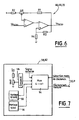
- FIG. figure 6 An exemplary embodiment of the gain amplification circuits 4, 16 or 64, the unit gain amplification circuit being conventionally produced by a simple operational amplifier mounted as a voltage follower, is illustrated on FIG. figure 6 .
- the input stage consists of an operational amplifier with field effect transistors (TEC) 90 for obtaining a very low offset current and little changing with the temperature.
- TEC field effect transistors
- the weakness of the bandwidth and the maximum rate of variation of its output voltage (slew-rate) of this amplifier to TEC is compensated by the presence at its output of a second operational amplifier with bipolar transistors 92 which has on the contrary a bandwidth and a very high slew-rate.
- the signal Ve from the multiplexer circuit 62a; 62b is directed to the non-inverting input of the first amplifier 90, its inverting input being connected to the midpoint of an adjustable potentiometer ⁇ R whose two ends are connected respectively to one end of a first resistor R1 whose other end is connected to the output of the second amplifier 92 and to one end of a second resistor R2 whose other end is connected to a positive reference potential.
- the output of the first amplifier constitutes the inverting input of the second amplifier whose non-inverting input is looped on the output of this second amplifier by a third resistor R3 and connected to a negative reference potential through a fourth resistor R4. .
- the synchronization module 58, 82 responsible for triggering the measurement process by activating the corresponding interrupt of the processor 50, 78 is represented on the figure 7 .
- This module comprises a four-channel multiplexer circuit to a channel 94 which receives respectively on each of its four inputs: an external signal, the output signals of two clock circuits 96, 98 of frequency 10 and 10000 Hz and the output signal a comparator 99 receiving at the input on the one hand the signal Vb and on the other hand a predetermined threshold voltage.
- the selection of one or the other of these signals is carried out from the signal processor 78 which thus generates four distinct synchronization modes: a slow mode for the calibration in which the constants A and B and the values of Vr and Vb are entered manually on the keyboard (in this mode, the measurement frequency is advantageously a few Hz, for example 10 Hz and the bandwidth on each channel is then limited) and three fast modes that differ by the triggering principle of the measurement .
- a slow mode for the calibration in which the constants A and B and the values of Vr and Vb are entered manually on the keyboard (in this mode, the measurement frequency is advantageously a few Hz, for example 10 Hz and the bandwidth on each channel is then limited) and three fast modes that differ by the triggering principle of the measurement .
- the temperature calculation is triggered by an external logic signal, which can then be executed up to 110,000 times per second.
- the calculation is triggered by the signal Vb as soon as it exceeds the predetermined threshold voltage.
- a fixed frequency synchronization mode the calculation is triggered
- the different frequencies mentioned above are given purely as an indication and it is possible, by modifying them, to adapt the pyrometer according to the invention to a very many situations.
- the pyrometer is capable of characterizing phenomena having natural periodicities (turbine blades for example) as processes having any prior variations.
- the processor waits, in a step 102, for an interruption signal that can be generated by the synchronization module 82 (temperature calculation function) or by the circuit 84 and display management (calibration function).
- the processor reads the voltage values Vr, Vb delivered by the fast converters 60a, 60b and, in step 106, it selects the gain best suited to the conversion. analog-digital it launches in a step 108. In parallel, in a step 110, it proceeds to calculate the ratio Vr / Vb (on the values resulting from the previous conversion). In the next step 112, it reads in the conversion table the value of the corresponding temperature and, in step 114, this value T is sent to a digital output or addressed to the converter 80 which delivers the analog equivalent t on its way out.
- step 116 the values Vr and Vb are read by the processor and saved for the next calculation and the gain is reset to 1 during the next step 118.
- the process either returns to the initial waiting state (step 102) or addresses the values of T and Vr / Vb to the management circuit of the display 84.
- the interruption results from the management circuit of the keyboard 84, an analysis of the message entered is carried out and the corresponding action is then executed. It can be a change of mode or a calibration with modification of the parameters A and B. This action is completed, the processor returns to its initial state of waiting for a new interruption coming from the keyboard or the synchronization module.
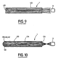
- FIGS. 9 and 10 illustrate two possible architectures for the measuring probe 1.
- these probes use a conventional optical fiber 120, without any focusing device, which is then placed opposite the surface whose temperature is to be measured, this surface being able to be temperature simply by moving a gas from the touch.
- a fiber is, for example, a multimode fiber with index jump in silica / silica (core / sheath).
- the transparent fiber is advantageously covered with a thin layer 122 of an opaque material which provides sufficient thermal and mechanical protection but specific to each application (deposition of a refractory material by plasma spraying, for example).
- the fiber-probe is connected to the transmission fiber 3 by a not shown connection.
- the probe is constituted by a cylindrical sapphire bar 130 whose radiation exposure face can be made in the form of a hemispherical cap 132 whose radius varies in a determined manner depending on the application considered. Of course, a simply perpendicular face can also be considered.
- the exit face of the sapphire facing the fiber is advantageously made in the form of a spherical cap 134 which allows a focusing of almost the entire flow to be conveyed in the fiber 3 (maximization of the optical coupling with the fiber) .
- This solution which avoids the use of a lens whose positioning is always delicate is particularly reliable given the small number of coins involved. It also has the advantage of low cost and that of maintaining the intrinsic qualities of the bar of sapphire.
- the outer surface of the bar has a thermal and mechanical protection 136.
- the hemispherical cap 132 is covered with various layers having for object to create at the free end of the sapphire a coating conferring a thermal emission of black body type.
- These layers whose total thickness does not exceed 10 to 15 ⁇ m (especially for obtaining a good temporal response) optimize on the one hand the emission and the thermal transfer and on the other hand thermomechanical behavior and chemical probe according to its environment (reducing or oxidizing medium).
- Each layer has a specific function; a first layer 138 highly emissive, and a second layer 142 opaque and highly conductive. Two layers are sufficient, however an intermediate layer 140 may be added to optimize the diffusion of heat and thus homogenize the temperature.
- This pyrometer can thus allow the knowledge of very complete experimental data on phenomena still little studied because out of reach of the classical instrumentation.
Landscapes
- Physics & Mathematics (AREA)
- General Physics & Mathematics (AREA)
- Spectroscopy & Molecular Physics (AREA)
- Radiation Pyrometers (AREA)
Claims (16)
- Schnelles bichromatisches Pyrometer, das zur Messung der Temperatur T eines Gases oder einer Oberfläche in Bewegung geeignet ist, aufweisend:- einen Meßfühler (1), welcher der Oberfläche gegenüber angeordnet oder in das Gas eingetaucht ist und eine für die Temperatur dieser Oberfläche oder dieses Gases charakteristische thermische Strahlung auffängt,- eine optische Einzelfaser (3), die mit dem Meßfühler verbunden ist und diese Strahlung übermittelt,- eine optische Baugruppe (2), die mit der optischen Faser verbunden ist und diese Strahlung empfängt, wobei diese optische Baugruppe Eingangs-Kollimationsmittel (20) zum Übertragen dieser Strahlung in der Gesamtheit, Mittel zum Zerlegen, die von einem dichroitischen Plättchen (22) gebildet werden, zum Zerlegen der übertragenen Strahlung in zwei verschiedene Spektralbanden, und Ausgangs-Fokussierungsmittel (24, 26) zum Bündeln der zerlegten Strahlungen enthält,- ein Quantenerfassungselement (2, 4), das diese zerlegten Strahlungen empfängt und ihre Umwandlung in zwei Spannungen der Farbe Vr, Vb sicherstellt,- ein Verarbeitungselement (5), das diese Spannungssignale empfängt, und das Analog-Digital-Umwandlungsmittel (52, 54; 76a, 76b), einen Signalverarbeitungs-Prozessor (DSP 50, 78), der ausgehend von diesen numerischen Werten ein Vr/Vb-Verhältnis berechnet, und Speichermittel (56, 88) enthält, die mit einer Tabelle von durch Eichen vorbestimmten Werten T=f(Vr/Vb) ausgestattet sind und am Ausgang, ausgehend von dem berechneten Verhältnis, die Temperatur T der Oberfläche oder des Gases liefern,- wobei das Verarbeitungselement (5) außerdem Mittel (60a, 60b) zur schnellen Umwandlung der Werte Vr und Vb zur Abschätzung ihrer Größenordnung aufweist und- wobei das Verarbeitungselement (5) außerdem Mittel zur Anpassung der Verstärkungsstufe der Signale Vr und Vb gemäß den von den schnellen Wandlern an den Prozessor gelieferten Größenordnungen aufweist.
- Schnelles bichromatisches Pyrometer, das zur Messung der Temperatur T einer Oberfläche geeignet ist, aufweisend:- eine gegenüber der Oberfläche angeordnete optische Baugruppe (2), die eine thermische Strahlung, welche von dieser Oberfläche emittiert wird und für ihre Temperatur charakteristisch ist, auffängt, und die Eingangs-Fokussierungsmittel (18), welche die emittierte Strahlung empfangen und im Brennpunkt der Eingangs-Kollimationsmittel (20) fokussieren, zum Übertragen der empfangenen Strahlung in der Gesamtheit, Mittel zum Zerlegen, die von einem dichroitischen Plättchen (22) gebildet werden, um diese Strahlung in zwei verschiedene Spektralbanden zu zerlegen, und Ausgangs-Fokussierungsmittel (24, 26) zum Bündeln der zerlegten Strahlungen enthält,- ein Quantenerfassungselement (2, 4), das diese zerlegten Strahlungen empfängt und ihre Umwandlung in zwei Spannungen der Farbe Vr, Vb sicherstellt, und- ein Verarbeitungselement (5), das diese Spannungssignale empfängt, und das Analog-Digital-Umwandlungsmittel (52, 54; 76a, 76b), einen Signalverarbeitungs-Prozessor (DSP 50, 78), der ausgehend von diesen numerischen Werten ein Vr/Vb-Verhältnis berechnet, und Speichermittel (56,88), die mit einer Tabelle von durch Eichung vorbestimmten Werten T=f(Vr/Vb) ausgestattet sind und am Ausgang, ausgehend von dem berechneten Verhältnis, die Temperatur T der Oberfläche liefern, enthält.
- Schnelles bichromatisches Pyrometer nach Anspruch 1 oder 2, dadurch gekennzeichnet, daß jedes der Ausgangs-Fokussierungsmittel (24, 26) der zerlegten Strahlungen vorgeschaltete Interferenzfiltermittel (30, 32) hat.
- Schnelles bichromatisches Pyrometer nach Anspruch 1 oder 2, dadurch gekennzeichnet, daß die Fokussierungsmittel (18, 24, 26) achromatische Zweilinser aufweisen.
- Schnelles bichromatisches Pyrometer nach Anspruch 1 oder 2, dadurch gekennzeichnet, daß die Mittel zur schnellen Umwandlung zwei Analog-Digital-Wandler vom Blitztyp enthalten.
- Schnelles bichromatisches Pyrometer nach Anspruch 1 oder 2, dadurch gekennzeichnet, daß die Mittel zur Anpassung für jedes Signal Vr oder Vb ein Multiplexer-Element, das einen Kanal in mindestens zwei Kanäle aufteilt (62a;62b), welches das Signal empfängt und es an eines von mindestens zwei Verstärkerelementen verschiedener Verstärkung (64a, 66a, 68a 70a; 64b, 66b, 68b, 70b) liefert, deren Ausgänge mit einem Demultiplexer-Element, das mindestens zwei Kanäle zu einem Kanal vereinigt (72a; 72b), verbunden sind, enthalten, wobei für jede Berechnung des Verhältnisses Vr/Vb ein einziges der Verstärkerelemente ausgewählt wird.
- Schnelles bichromatisches Pyrometer nach Anspruch 1 oder 2, dadurch gekennzeichnet, daß das Verarbeitungselement (5) außerdem Digital-Analog-Umwandlungsmittel (80), die am Ausgang des Signalprozessors angeordnet und dazu geeignet sind, einen analogen Wert der gemessenen Temperatur zu erhalten, aufweist.
- Schnelles bichromatisches Pyrometer nach Anspruch 1 oder 2, dadurch gekennzeichnet, daß das Erfassungselement zwei Quantendetektoren (33, 34) vom InGaAs-Typ aufweist.
- Schnelles bichromatisches Pyrometer nach Anspruch 1 oder 2, dadurch gekennzeichnet, daß die Speichermittel zum Speichern einen schnellen Speicher vom Flashtyp enthalten.
- Schnelles bichromatisches Pyrometer nach Anspruch 1 oder 2, dadurch gekennzeichnet, daß das Verarbeitungselement (5) ersetzt ist durch ein Element, das einen analogen Teiler (40) aufweist, der die Signale Vr und Vb empfängt und das Verhältnis Vr/Vb für einen Analog-Digital-Wandler (42) liefert, dessen Ausgang mit einem Speicherelement (44) verbunden ist, welches eine Tabelle des Wertes T=f(Vr/Vb) enthält und die gemessene Temperatur T liefert.
- Schnelles bichromatisches Pyrometer nach Anspruch 1, dadurch gekennzeichnet, daß der Meßfühler einen Saphir-Stab (130), der mit einer dünnen Schutzschicht (136) bedeckt ist, und dessen der Faser (3) gegenüberliegen des Ende eine kugelförmige Kappe (134) aufweist, die in der Faser fast die Gesamtheit der emittierten Strahlung fokussiert, aufweist.
- Schnelles bichromatisches Pyrometer nach Anspruch 1, dadurch gekennzeichnet, daß das Ende des Meßfühlers, das die Strahlung der Oberfläche empfängt, eine halbkugelförmige Kappe (132) aufweist, deren Radius entsprechend dem Abstand von der Oberfläche festgelegt ist.
- Schnelles bichromatisches Pyrometer nach Anspruch 1 oder 12, das insbesondere geeignet ist zur Messung der Temperatur von Gasen, dadurch gekennzeichnet, daß ein Ende des Meßfühlers, das die Strahlung empfängt, mit einer Beschichtung bedeckt ist, die ihm eine thermische Ausstrahlung vom Typ schwarzer Körper verleiht.
- Schnelles bichromatisches Pyrometer nach Anspruch 13, dadurch gekennzeichnet, daß die Beschichtung aus einer stark emittierenden ersten Schicht (138) und einer zweiten Schicht (142), die lichtundurchlässig und stark leitfähig ist, besteht.
- Schnelles bichromatisches Pyrometer nach Anspruch 14, dadurch gekennzeichnet, daß die Beschichtung außerdem eine Zwischenschicht (140) aufweist, die zwischen der ersten und der zweiten Schicht (138, 142) angeordnet ist und eine Optimierung der Wärme-Diffusion und eine Vergleichmäßigung der Temperatur sicherstellt.
- Verfahren zur Messung der Temperatur eines Gases oder einer Oberfläche in Bewegung durch die Bestimmung und Verarbeitung einer thermischen Strahlung, die für die Temperatur dieser Oberfläche oder dieses Gases charakteristisch ist, unter Verwendung des schnellen bichromatischen Pyrometers nach Anspruch 1, dadurch gekennzeichnet, daß es die folgenden Schritte aufweist:1) Auffangen einer thermischen Strahlung, die für die Temperatur der Oberfläche oder des Gases charakteristisch ist,2) Zerlegen dieser Strahlung in zwei Strahlungen unterschiedlicher Spektralbanden,3) Umwandeln dieser zwei Strahlungen in zwei Spannungen der Farbe Vr und Vb,4) Abschätzen der Größenordnungen der Spannungen der Farbe Vr und Vb, um die Verstärkung eines Verstärkungselements dieser Spannungen anzupassen,5) Berechnen ihres Verhältnisses Vr/Vb, und6) Entnehmen des der gemessenen Temperatur T entsprechenden Werts aus einer Umrechnungstabelle T=f(Vr/Vb), die vorher durch Eichung bestimmt wurde.
Applications Claiming Priority (2)
| Application Number | Priority Date | Filing Date | Title |
|---|---|---|---|
| FR9412588A FR2726081B1 (fr) | 1994-10-21 | 1994-10-21 | Pyrometre bichromatique rapide a fibre optique |
| FR9412588 | 1994-10-21 |
Publications (3)
| Publication Number | Publication Date |
|---|---|
| EP0708317A1 EP0708317A1 (de) | 1996-04-24 |
| EP0708317B1 EP0708317B1 (de) | 2002-01-30 |
| EP0708317B2 true EP0708317B2 (de) | 2010-06-09 |
Family
ID=9468078
Family Applications (1)
| Application Number | Title | Priority Date | Filing Date |
|---|---|---|---|
| EP95402286A Expired - Lifetime EP0708317B2 (de) | 1994-10-21 | 1995-10-13 | Schnelles bichromatisches fiberoptisches Pyrometer |
Country Status (5)
| Country | Link |
|---|---|
| US (1) | US5755510A (de) |
| EP (1) | EP0708317B2 (de) |
| DE (1) | DE69525212T3 (de) |
| ES (1) | ES2171514T5 (de) |
| FR (1) | FR2726081B1 (de) |
Cited By (1)
| Publication number | Priority date | Publication date | Assignee | Title |
|---|---|---|---|---|
| DE102011016102A1 (de) * | 2011-01-07 | 2012-07-12 | Heraeus Noblelight Gmbh | Verfahren zur Bestimmung der Infrarot-Abstrahlung |
Families Citing this family (19)
| Publication number | Priority date | Publication date | Assignee | Title |
|---|---|---|---|---|
| FR2773878B1 (fr) * | 1998-01-20 | 2000-04-07 | Auxitrol Sa | Capteur de mesure d'une temperature |
| FR2773879B1 (fr) * | 1998-01-20 | 2001-01-26 | Auxitrol Sa | Capteur de mesure d'une temperature |
| US6373562B1 (en) * | 1998-10-09 | 2002-04-16 | Kim A. Marsh | Fiberoptic cable tester |
| US6151446A (en) * | 1999-07-06 | 2000-11-21 | Applied Materials, Inc. | Apparatus and method for thermally processing substrates including a processor using multiple detection signals |
| US7690840B2 (en) * | 1999-12-22 | 2010-04-06 | Siemens Energy, Inc. | Method and apparatus for measuring on-line failure of turbine thermal barrier coatings |
| GB0000954D0 (en) * | 2000-01-18 | 2000-03-08 | Renishaw Plc | Spectroscopic probe |
| US6698920B1 (en) * | 2000-05-08 | 2004-03-02 | General Electric Company | Temperature measuring system and optical switch used therein |
| US6786634B2 (en) * | 2001-10-10 | 2004-09-07 | Noritake Co., Limited | Temperature measuring method and apparatus |
| US20040179575A1 (en) * | 2003-01-23 | 2004-09-16 | Markham James R. | Instrument for temperature and condition monitoring of advanced turbine blades |
| US7075629B2 (en) * | 2003-05-12 | 2006-07-11 | Honeywell International Inc. | High temperature pyrometer |
| US7826954B2 (en) * | 2004-06-25 | 2010-11-02 | Honda Motor Co., Ltd. | System for monitoring sensor outputs of a gas turbine engine |
| US7432505B2 (en) * | 2006-05-04 | 2008-10-07 | Siemens Power Generation, Inc. | Infrared-based method and apparatus for online detection of cracks in steam turbine components |
| US7633066B2 (en) * | 2006-05-22 | 2009-12-15 | General Electric Company | Multiwavelength pyrometry systems |
| US8790006B2 (en) * | 2009-11-30 | 2014-07-29 | General Electric Company | Multiwavelength thermometer |
| US20120230366A1 (en) * | 2011-03-10 | 2012-09-13 | Yaosheng Chen | Optical Digital Thermometer |
| DE102012011924B3 (de) * | 2012-06-15 | 2013-11-21 | Keller Hcw Gmbh | Verfahren und Vorrichtung zur berührungslosen Temperaturmessung an bewegten, langgestreckten Messobjekten |
| US11215508B2 (en) * | 2019-02-01 | 2022-01-04 | Solar Turbines Incorporated | Temperature measuring system |
| CN110455417B (zh) * | 2019-08-21 | 2020-08-04 | 北京环境特性研究所 | 针对红外光学系统杂散辐射的定量测量误差校正方法 |
| US12487124B2 (en) * | 2022-01-31 | 2025-12-02 | General Electric Company | Systems and methods for measuring temperature |
Citations (4)
| Publication number | Priority date | Publication date | Assignee | Title |
|---|---|---|---|---|
| DE1648233A1 (de) † | 1967-04-18 | 1972-01-13 | Inst Metallurg Im A A Bajkowa | Verfahren und Einrichtung zum Messen der wahren Koerpertemperatur nach der Ausstrahlung |
| DE3202089C2 (de) † | 1982-01-23 | 1985-01-17 | Fa. Carl Zeiss, 7920 Heidenheim | Faseroptischer Temperatursensor |
| DE2755713C2 (de) † | 1976-12-16 | 1987-06-25 | Luxtron Corp., Mountain View, Calif., Us | |
| US5021980A (en) † | 1989-02-21 | 1991-06-04 | Lsi Logic Corporation | Remote measurement of temperature |
Family Cites Families (14)
| Publication number | Priority date | Publication date | Assignee | Title |
|---|---|---|---|---|
| US3922550A (en) * | 1973-12-28 | 1975-11-25 | Raytheon Co | Radiometric system |
| DE2405651B2 (de) * | 1974-02-04 | 1980-08-14 | Mannesmann Ag, 4000 Duesseldorf | Pyrometer |
| GB1602160A (en) * | 1978-04-26 | 1981-11-11 | Negretti & Zambra Aviat Ltd | Pyrometers |
| GB2068109B (en) * | 1980-01-21 | 1984-05-23 | Europ Electronic Syst Ltd | Monitoring strip temperature |
| GB8416201D0 (en) * | 1984-06-26 | 1984-08-01 | Land Infrared Ltd | Temperature monitoring |
| EP0216458B1 (de) * | 1985-08-08 | 1990-10-24 | Rosemount Inc. | Pyrometer zur Temperaturmessung |
| US4764025A (en) * | 1985-08-08 | 1988-08-16 | Rosemount Inc. | Turbine blade temperature detecting pyrometer |
| US5188458A (en) * | 1988-04-27 | 1993-02-23 | A G Processing Technologies, Inc. | Pyrometer apparatus and method |
| FI894146A7 (fi) * | 1989-09-04 | 1991-03-05 | Rolf Hernberg | Menetelmä ja laitteisto leijukerroksessa olevien polttoainehiukkasten lämpötilan mittaamiseksi |
| CA2028352A1 (en) * | 1989-10-25 | 1991-04-26 | Kyung-Shik Lee | High temperature sensor |
| US5154512A (en) * | 1990-04-10 | 1992-10-13 | Luxtron Corporation | Non-contact techniques for measuring temperature or radiation-heated objects |
| DE4028408C2 (de) * | 1990-09-07 | 1996-03-21 | Tzn Forschung & Entwicklung | Verfahren zur berührungslosen Temperaturmessung |
| GB9113966D0 (en) * | 1991-06-28 | 1991-08-14 | Ferodo Ltd | Apparatus for temperature detection |
| FR2703455B1 (fr) * | 1993-04-01 | 1995-05-12 | Europ Gas Turbines Sa | Pyromètre bichromatique. |
-
1994
- 1994-10-21 FR FR9412588A patent/FR2726081B1/fr not_active Expired - Fee Related
-
1995
- 1995-10-13 EP EP95402286A patent/EP0708317B2/de not_active Expired - Lifetime
- 1995-10-13 DE DE69525212T patent/DE69525212T3/de not_active Expired - Lifetime
- 1995-10-13 ES ES95402286T patent/ES2171514T5/es not_active Expired - Lifetime
- 1995-10-20 US US08/546,454 patent/US5755510A/en not_active Expired - Lifetime
Patent Citations (4)
| Publication number | Priority date | Publication date | Assignee | Title |
|---|---|---|---|---|
| DE1648233A1 (de) † | 1967-04-18 | 1972-01-13 | Inst Metallurg Im A A Bajkowa | Verfahren und Einrichtung zum Messen der wahren Koerpertemperatur nach der Ausstrahlung |
| DE2755713C2 (de) † | 1976-12-16 | 1987-06-25 | Luxtron Corp., Mountain View, Calif., Us | |
| DE3202089C2 (de) † | 1982-01-23 | 1985-01-17 | Fa. Carl Zeiss, 7920 Heidenheim | Faseroptischer Temperatursensor |
| US5021980A (en) † | 1989-02-21 | 1991-06-04 | Lsi Logic Corporation | Remote measurement of temperature |
Cited By (1)
| Publication number | Priority date | Publication date | Assignee | Title |
|---|---|---|---|---|
| DE102011016102A1 (de) * | 2011-01-07 | 2012-07-12 | Heraeus Noblelight Gmbh | Verfahren zur Bestimmung der Infrarot-Abstrahlung |
Also Published As
| Publication number | Publication date |
|---|---|
| EP0708317A1 (de) | 1996-04-24 |
| ES2171514T5 (es) | 2010-10-28 |
| EP0708317B1 (de) | 2002-01-30 |
| US5755510A (en) | 1998-05-26 |
| FR2726081A1 (fr) | 1996-04-26 |
| DE69525212T3 (de) | 2010-12-30 |
| FR2726081B1 (fr) | 1997-01-10 |
| ES2171514T3 (es) | 2002-09-16 |
| DE69525212D1 (de) | 2002-03-14 |
| DE69525212T2 (de) | 2002-10-24 |
Similar Documents
| Publication | Publication Date | Title |
|---|---|---|
| EP0708317B2 (de) | Schnelles bichromatisches fiberoptisches Pyrometer | |
| Pan et al. | Mid-infrared Nb4N3-based superconducting nanowire single photon detectors for wavelengths up to 10 µm | |
| EP0618432A2 (de) | Zwei-Farben Pyrometer | |
| EP0187087B1 (de) | Photonenabtasteinrichtung und diese Einrichtung benutzendes Transientenanalysesystem | |
| EP0020238A1 (de) | Verfahren und Vorrichtung zum Messen der thermischen Übertragung eines Prüflings und Anwendung beim Messen des Absorptionskoeffizienten | |
| Shiokawa et al. | Three-channel imaging Fabry–Perot interferometer for measurement of mid-latitude airglow | |
| Whiteman et al. | Comments on “Accuracy of Raman lidar water vapor calibration and its applicability to long-term measurements” | |
| CA2881524C (fr) | Dispositif d'amplification analogique destine notamment a un anemometre laser | |
| FR2847978A1 (fr) | Spectrometre compact a composant optique monolithique | |
| WO2003006960A1 (fr) | Dispositif et procede de radiometrie pour determiner in situ le contenu biochimique de feuilles, et appareil portatif integrant ce dispositif | |
| EP4720636A1 (de) | System zur messung mindestens einer chemischen komponente eines strömenden fluids für ein elektrochemisches generatorsystem | |
| Boboridis et al. | A High‐Speed Four‐Channel Infrared Pyrometer | |
| WO2006037879A1 (fr) | Detection des emissions de fluorescence induite par un laser | |
| WO2020016259A1 (fr) | Méthode et dispositif de caractérisation de filtres optiques | |
| EP4094069A1 (de) | System zur erfassung von punktwerten zur bildung eines bildes mit terahertzstrahlung | |
| Subash et al. | UV to IR high-efficiency antireflective surface modification of freeform and cylindrical lenses for space platform optical instrumentation | |
| FR2711792A1 (fr) | Dispositif de mesure de flux lumineux. | |
| EP3968066A1 (de) | Wellenleiter, der eine optische multimode-faser umfasst und die geführten moden räumlich konzentrieren kann | |
| EP0052551B1 (de) | Refraktometer mit Verwendung des Grenzwinkelverfahrens | |
| WO2021152244A1 (fr) | Système de mesure d'une pluralité de paramètres physiques en un point de mesure par une fibre optique multimode | |
| WO2023118462A1 (fr) | Procede et dispositif de type pyroreflectometre bichromatique pour determiner la temperature d'une surface | |
| FR2810108A1 (fr) | Ellipsometre spectroscopique a faible bruit | |
| EP3994430B1 (de) | Messvorrichtung mit einer optischen verbindungsfaser und einem messgerät zur instrumentierung eines aeronautischen systems sowie ein solches messgerät enthaltendes aeronautisches system | |
| FR3149091A1 (fr) | Système de mesure d’au moins un composant chimique d’un fluide en flux pour système générateur électrochimique | |
| WO2020104560A1 (fr) | Réfractomètre à fibre optique hybride pour la mesure d'indice de réfraction d'un fluide et capteur correspondant |
Legal Events
| Date | Code | Title | Description |
|---|---|---|---|
| PUAI | Public reference made under article 153(3) epc to a published international application that has entered the european phase |
Free format text: ORIGINAL CODE: 0009012 |
|
| AK | Designated contracting states |
Kind code of ref document: A1 Designated state(s): CH DE ES GB LI |
|
| 17P | Request for examination filed |
Effective date: 19960905 |
|
| RAP1 | Party data changed (applicant data changed or rights of an application transferred) |
Owner name: SOCIETE NATIONALE D'ETUDE ET DE CONSTRUCTION DE MO |
|
| 17Q | First examination report despatched |
Effective date: 19981001 |
|
| GRAG | Despatch of communication of intention to grant |
Free format text: ORIGINAL CODE: EPIDOS AGRA |
|
| GRAG | Despatch of communication of intention to grant |
Free format text: ORIGINAL CODE: EPIDOS AGRA |
|
| GRAH | Despatch of communication of intention to grant a patent |
Free format text: ORIGINAL CODE: EPIDOS IGRA |
|
| GRAH | Despatch of communication of intention to grant a patent |
Free format text: ORIGINAL CODE: EPIDOS IGRA |
|
| GRAA | (expected) grant |
Free format text: ORIGINAL CODE: 0009210 |
|
| REG | Reference to a national code |
Ref country code: GB Ref legal event code: IF02 |
|
| AK | Designated contracting states |
Kind code of ref document: B1 Designated state(s): CH DE ES GB LI |
|
| REG | Reference to a national code |
Ref country code: CH Ref legal event code: EP |
|
| REF | Corresponds to: |
Ref document number: 69525212 Country of ref document: DE Date of ref document: 20020314 |
|
| REG | Reference to a national code |
Ref country code: CH Ref legal event code: NV Representative=s name: MICHELI & CIE INGENIEURS-CONSEILS |
|
| GBT | Gb: translation of ep patent filed (gb section 77(6)(a)/1977) |
Effective date: 20020501 |
|
| REG | Reference to a national code |
Ref country code: ES Ref legal event code: FG2A Ref document number: 2171514 Country of ref document: ES Kind code of ref document: T3 |
|
| PLBQ | Unpublished change to opponent data |
Free format text: ORIGINAL CODE: EPIDOS OPPO |
|
| PLBI | Opposition filed |
Free format text: ORIGINAL CODE: 0009260 |
|
| PLBF | Reply of patent proprietor to notice(s) of opposition |
Free format text: ORIGINAL CODE: EPIDOS OBSO |
|
| 26 | Opposition filed |
Opponent name: DIAS ANGEWANDTE SENSORIK GMBH Effective date: 20021023 |
|
| PLBF | Reply of patent proprietor to notice(s) of opposition |
Free format text: ORIGINAL CODE: EPIDOS OBSO |
|
| PLBF | Reply of patent proprietor to notice(s) of opposition |
Free format text: ORIGINAL CODE: EPIDOS OBSO |
|
| PLCK | Communication despatched that opposition was rejected |
Free format text: ORIGINAL CODE: EPIDOSNREJ1 |
|
| APBP | Date of receipt of notice of appeal recorded |
Free format text: ORIGINAL CODE: EPIDOSNNOA2O |
|
| APAH | Appeal reference modified |
Free format text: ORIGINAL CODE: EPIDOSCREFNO |
|
| APBQ | Date of receipt of statement of grounds of appeal recorded |
Free format text: ORIGINAL CODE: EPIDOSNNOA3O |
|
| APBU | Appeal procedure closed |
Free format text: ORIGINAL CODE: EPIDOSNNOA9O |
|
| PLAY | Examination report in opposition despatched + time limit |
Free format text: ORIGINAL CODE: EPIDOSNORE2 |
|
| PLAY | Examination report in opposition despatched + time limit |
Free format text: ORIGINAL CODE: EPIDOSNORE2 |
|
| PLBC | Reply to examination report in opposition received |
Free format text: ORIGINAL CODE: EPIDOSNORE3 |
|
| PUAH | Patent maintained in amended form |
Free format text: ORIGINAL CODE: 0009272 |
|
| STAA | Information on the status of an ep patent application or granted ep patent |
Free format text: STATUS: PATENT MAINTAINED AS AMENDED |
|
| 27A | Patent maintained in amended form |
Effective date: 20100609 |
|
| AK | Designated contracting states |
Kind code of ref document: B2 Designated state(s): CH DE ES GB LI |
|
| REG | Reference to a national code |
Ref country code: CH Ref legal event code: AEN Free format text: BREVET MAINTENU DANS UNE FORME MODIFIEE |
|
| REG | Reference to a national code |
Ref country code: ES Ref legal event code: DC2A Date of ref document: 20100908 Kind code of ref document: T5 |
|
| PGFP | Annual fee paid to national office [announced via postgrant information from national office to epo] |
Ref country code: DE Payment date: 20100930 Year of fee payment: 16 |
|
| PGFP | Annual fee paid to national office [announced via postgrant information from national office to epo] |
Ref country code: CH Payment date: 20110923 Year of fee payment: 17 |
|
| PGFP | Annual fee paid to national office [announced via postgrant information from national office to epo] |
Ref country code: GB Payment date: 20110926 Year of fee payment: 17 |
|
| PGFP | Annual fee paid to national office [announced via postgrant information from national office to epo] |
Ref country code: ES Payment date: 20111006 Year of fee payment: 17 |
|
| REG | Reference to a national code |
Ref country code: GB Ref legal event code: 732E Free format text: REGISTERED BETWEEN 20120517 AND 20120523 |
|
| REG | Reference to a national code |
Ref country code: ES Ref legal event code: PC2A Owner name: SNECMA Effective date: 20120816 |
|
| REG | Reference to a national code |
Ref country code: DE Ref legal event code: R082 Ref document number: 69525212 Country of ref document: DE Representative=s name: MAIWALD PATENTANWALTSGESELLSCHAFT MBH, DE |
|
| REG | Reference to a national code |
Ref country code: DE Ref legal event code: R082 Ref document number: 69525212 Country of ref document: DE Representative=s name: MAIWALD PATENTANWALTSGESELLSCHAFT MBH, DE Effective date: 20121005 Ref country code: DE Ref legal event code: R081 Ref document number: 69525212 Country of ref document: DE Owner name: SNECMA, FR Free format text: FORMER OWNER: SOCIETE NATIONALE D'ETUDE ET DE CONSTRUCTION DE MOTEURS D'AVIATION (S.N.E.C.M.A.), PARIS, FR Effective date: 20121005 |
|
| REG | Reference to a national code |
Ref country code: CH Ref legal event code: PL |
|
| GBPC | Gb: european patent ceased through non-payment of renewal fee |
Effective date: 20121013 |
|
| PG25 | Lapsed in a contracting state [announced via postgrant information from national office to epo] |
Ref country code: GB Free format text: LAPSE BECAUSE OF NON-PAYMENT OF DUE FEES Effective date: 20121013 Ref country code: DE Free format text: LAPSE BECAUSE OF NON-PAYMENT OF DUE FEES Effective date: 20130501 Ref country code: LI Free format text: LAPSE BECAUSE OF NON-PAYMENT OF DUE FEES Effective date: 20121031 Ref country code: CH Free format text: LAPSE BECAUSE OF NON-PAYMENT OF DUE FEES Effective date: 20121031 |
|
| REG | Reference to a national code |
Ref country code: DE Ref legal event code: R119 Ref document number: 69525212 Country of ref document: DE Effective date: 20130501 |
|
| REG | Reference to a national code |
Ref country code: ES Ref legal event code: FD2A Effective date: 20140116 |
|
| PG25 | Lapsed in a contracting state [announced via postgrant information from national office to epo] |
Ref country code: ES Free format text: LAPSE BECAUSE OF NON-PAYMENT OF DUE FEES Effective date: 20121014 |