EP0708317B2 - Rapid fiberoptic bichromatic pyrometer - Google Patents
Rapid fiberoptic bichromatic pyrometer Download PDFInfo
- Publication number
- EP0708317B2 EP0708317B2 EP95402286A EP95402286A EP0708317B2 EP 0708317 B2 EP0708317 B2 EP 0708317B2 EP 95402286 A EP95402286 A EP 95402286A EP 95402286 A EP95402286 A EP 95402286A EP 0708317 B2 EP0708317 B2 EP 0708317B2
- Authority
- EP
- European Patent Office
- Prior art keywords
- fast
- radiation
- temperature
- circuit
- bichromatic
- Prior art date
- Legal status (The legal status is an assumption and is not a legal conclusion. Google has not performed a legal analysis and makes no representation as to the accuracy of the status listed.)
- Expired - Lifetime
Links
Images


Classifications
-
- G—PHYSICS
- G01—MEASURING; TESTING
- G01J—MEASUREMENT OF INTENSITY, VELOCITY, SPECTRAL CONTENT, POLARISATION, PHASE OR PULSE CHARACTERISTICS OF INFRARED, VISIBLE OR ULTRAVIOLET LIGHT; COLORIMETRY; RADIATION PYROMETRY
- G01J5/00—Radiation pyrometry, e.g. infrared or optical thermometry
- G01J5/02—Constructional details
- G01J5/04—Casings
-
- G—PHYSICS
- G01—MEASURING; TESTING
- G01J—MEASUREMENT OF INTENSITY, VELOCITY, SPECTRAL CONTENT, POLARISATION, PHASE OR PULSE CHARACTERISTICS OF INFRARED, VISIBLE OR ULTRAVIOLET LIGHT; COLORIMETRY; RADIATION PYROMETRY
- G01J5/00—Radiation pyrometry, e.g. infrared or optical thermometry
- G01J5/0014—Radiation pyrometry, e.g. infrared or optical thermometry for sensing the radiation from gases, flames
-
- G—PHYSICS
- G01—MEASURING; TESTING
- G01J—MEASUREMENT OF INTENSITY, VELOCITY, SPECTRAL CONTENT, POLARISATION, PHASE OR PULSE CHARACTERISTICS OF INFRARED, VISIBLE OR ULTRAVIOLET LIGHT; COLORIMETRY; RADIATION PYROMETRY
- G01J5/00—Radiation pyrometry, e.g. infrared or optical thermometry
- G01J5/0022—Radiation pyrometry, e.g. infrared or optical thermometry for sensing the radiation of moving bodies
-
- G—PHYSICS
- G01—MEASURING; TESTING
- G01J—MEASUREMENT OF INTENSITY, VELOCITY, SPECTRAL CONTENT, POLARISATION, PHASE OR PULSE CHARACTERISTICS OF INFRARED, VISIBLE OR ULTRAVIOLET LIGHT; COLORIMETRY; RADIATION PYROMETRY
- G01J5/00—Radiation pyrometry, e.g. infrared or optical thermometry
- G01J5/0088—Radiation pyrometry, e.g. infrared or optical thermometry in turbines
-
- G—PHYSICS
- G01—MEASURING; TESTING
- G01J—MEASUREMENT OF INTENSITY, VELOCITY, SPECTRAL CONTENT, POLARISATION, PHASE OR PULSE CHARACTERISTICS OF INFRARED, VISIBLE OR ULTRAVIOLET LIGHT; COLORIMETRY; RADIATION PYROMETRY
- G01J5/00—Radiation pyrometry, e.g. infrared or optical thermometry
- G01J5/02—Constructional details
- G01J5/0215—Compact construction
-
- G—PHYSICS
- G01—MEASURING; TESTING
- G01J—MEASUREMENT OF INTENSITY, VELOCITY, SPECTRAL CONTENT, POLARISATION, PHASE OR PULSE CHARACTERISTICS OF INFRARED, VISIBLE OR ULTRAVIOLET LIGHT; COLORIMETRY; RADIATION PYROMETRY
- G01J5/00—Radiation pyrometry, e.g. infrared or optical thermometry
- G01J5/02—Constructional details
- G01J5/026—Control of working procedures of a pyrometer, other than calibration; Bandwidth calculation; Gain control
-
- G—PHYSICS
- G01—MEASURING; TESTING
- G01J—MEASUREMENT OF INTENSITY, VELOCITY, SPECTRAL CONTENT, POLARISATION, PHASE OR PULSE CHARACTERISTICS OF INFRARED, VISIBLE OR ULTRAVIOLET LIGHT; COLORIMETRY; RADIATION PYROMETRY
- G01J5/00—Radiation pyrometry, e.g. infrared or optical thermometry
- G01J5/02—Constructional details
- G01J5/04—Casings
- G01J5/048—Protective parts
-
- G—PHYSICS
- G01—MEASURING; TESTING
- G01J—MEASUREMENT OF INTENSITY, VELOCITY, SPECTRAL CONTENT, POLARISATION, PHASE OR PULSE CHARACTERISTICS OF INFRARED, VISIBLE OR ULTRAVIOLET LIGHT; COLORIMETRY; RADIATION PYROMETRY
- G01J5/00—Radiation pyrometry, e.g. infrared or optical thermometry
- G01J5/02—Constructional details
- G01J5/08—Optical arrangements
- G01J5/0801—Means for wavelength selection or discrimination
-
- G—PHYSICS
- G01—MEASURING; TESTING
- G01J—MEASUREMENT OF INTENSITY, VELOCITY, SPECTRAL CONTENT, POLARISATION, PHASE OR PULSE CHARACTERISTICS OF INFRARED, VISIBLE OR ULTRAVIOLET LIGHT; COLORIMETRY; RADIATION PYROMETRY
- G01J5/00—Radiation pyrometry, e.g. infrared or optical thermometry
- G01J5/02—Constructional details
- G01J5/08—Optical arrangements
- G01J5/0806—Focusing or collimating elements, e.g. lenses or concave mirrors
-
- G—PHYSICS
- G01—MEASURING; TESTING
- G01J—MEASUREMENT OF INTENSITY, VELOCITY, SPECTRAL CONTENT, POLARISATION, PHASE OR PULSE CHARACTERISTICS OF INFRARED, VISIBLE OR ULTRAVIOLET LIGHT; COLORIMETRY; RADIATION PYROMETRY
- G01J5/00—Radiation pyrometry, e.g. infrared or optical thermometry
- G01J5/02—Constructional details
- G01J5/08—Optical arrangements
- G01J5/0813—Planar mirrors; Parallel phase plates
-
- G—PHYSICS
- G01—MEASURING; TESTING
- G01J—MEASUREMENT OF INTENSITY, VELOCITY, SPECTRAL CONTENT, POLARISATION, PHASE OR PULSE CHARACTERISTICS OF INFRARED, VISIBLE OR ULTRAVIOLET LIGHT; COLORIMETRY; RADIATION PYROMETRY
- G01J5/00—Radiation pyrometry, e.g. infrared or optical thermometry
- G01J5/02—Constructional details
- G01J5/08—Optical arrangements
- G01J5/0818—Waveguides
- G01J5/0821—Optical fibres
-
- G—PHYSICS
- G01—MEASURING; TESTING
- G01J—MEASUREMENT OF INTENSITY, VELOCITY, SPECTRAL CONTENT, POLARISATION, PHASE OR PULSE CHARACTERISTICS OF INFRARED, VISIBLE OR ULTRAVIOLET LIGHT; COLORIMETRY; RADIATION PYROMETRY
- G01J5/00—Radiation pyrometry, e.g. infrared or optical thermometry
- G01J5/02—Constructional details
- G01J5/08—Optical arrangements
- G01J5/0887—Integrating cavities mimicking black bodies, wherein the heat propagation between the black body and the measuring element does not occur within a solid; Use of bodies placed inside the fluid stream for measurement of the temperature of gases; Use of the reemission from a surface, e.g. reflective surface; Emissivity enhancement by multiple reflections
-
- G—PHYSICS
- G01—MEASURING; TESTING
- G01J—MEASUREMENT OF INTENSITY, VELOCITY, SPECTRAL CONTENT, POLARISATION, PHASE OR PULSE CHARACTERISTICS OF INFRARED, VISIBLE OR ULTRAVIOLET LIGHT; COLORIMETRY; RADIATION PYROMETRY
- G01J5/00—Radiation pyrometry, e.g. infrared or optical thermometry
- G01J5/60—Radiation pyrometry, e.g. infrared or optical thermometry using determination of colour temperature
- G01J5/602—Radiation pyrometry, e.g. infrared or optical thermometry using determination of colour temperature using selective, monochromatic or bandpass filtering
Definitions
- the present invention relates to a pyrometer for the realization of thermal diagnostics (measurement of gas temperatures or moving surfaces) in a severe environment, with a very high speed of measurement.
- Measurement errors related to optical transmission problems can notably exist in devices using a monochromatic optical fiber for capturing and transporting thermal radiation emitted by the moving turbine.
- a separator cube In bichromatic measurement devices in which it is necessary to proceed to the separation of the light beam at the output of the transport fiber, it is conventional to use a separator cube because it has a high homogeneity with the fiber.
- such a cube is particularly sensitive to vibrations and possible shocks and the distribution of the luminous flux at its output can then be modified.
- European demand EP-A-216458 an optical pyrometer using an optical fiber whose output light energy is divided into two elementary beams which limits both the response time and the resolution of such a pyrometer. More simply chromatic aberrations can appear when the fiber output beam is poorly collimated ( WO-A-91/03715 ).
- the processing of the signals from the separation means is generally performed in real time in an analog form using conventional discrete components. This results in significant response times (of the order of a millisecond) and, in the case of measurements at high frequencies, particularly important operating constraints.
- the stabilization of the measuring device imposes a limitation of the bandwidth and consequently of the overall rate (speed) of measurement.
- such a device remains sensitive to all phenomena of drift in voltage or temperature, the removal of which can then be considered only at the cost of frequent and tedious adjustments.
- the combination of the splitter cube optical system and the aforementioned analog electronic assembly does not make it possible to achieve a miniaturized device whose need is however present in particular in embedded systems where such a device would be useful for clarifying the limits of operation of turbine engines and in particular the control of their transient conditions.
- the present invention aims to overcome the aforementioned drawbacks and to provide a particularly compact pyrometer adapted to fast detection rates so that it can perform continuously, in a wide range of temperatures, instantaneous temperature measurements. in particular rotating turbine blades.
- the structure thus defined results in obtaining a particularly compact pyrometer, with the use of a dichroic blade as a separator device, and fast, by the use of a signal processor combined with a fast memory containing a conversion table. pre-established, in particular allowing the instantaneous measurement of the temperature of rotating turbine blades.
- the offset of the measurement is not essential and the measurement can be made directly from the optical block which will then be advantageously provided with means for focusing the radiation emitted by the surface.
- Measurements can be made from wide spectral bands to monochromatic domains where it is necessary for each of the separate radiation output focusing means to be preceded by interference filtering means.
- the focusing means comprise achromatic doubles.
- the fast conversion means advantageously comprise two analog-to-digital converters of the flash type.
- the means for adapting the amplification level comprise, preferably for each signal Vr or Vb, a multiplexer circuit a pathway to at least two channels receiving the signal and delivering it to one of at least two amplification circuits. different gain whose outputs are connected to a demultiplexer circuit of at least two channels to a channel, only one of the amplification circuits being selected at each calculation of the Vr / Vb ratio.
- the processing circuit may also include digital-to-analog conversion means placed at the output of the signal processor and intended to obtain an analog value of the measured temperature.
- the detection circuit comprises two quantic detectors of the InGaAs type. These detectors transform the radiation they receive into an electric current proportional to the power of this radiation.
- the storage means comprise a flash-type fast memory which is well adapted to a DSP-type processor.
- the measuring probe comprises a sapphire bar covered with a thin protective layer and whose end facing the fiber has a spherical cap focusing in the fiber almost all radiation emitted.
- the other end of the measuring probe receiving the radiation may comprise a hemispherical cap whose radius is determined according to the distance to the surface.
- the end of the measuring probe is covered with a coating conferring a thermal emission of black body type.
- This coating consists of a first highly emissive layer, and a second layer opaque to light and strongly conductive. It can also be provided with an intermediate layer placed between the first and second layers and ensuring optimization of the heat diffusion and homogenization of the temperature. If these layers optimize the emission and the heat transfer, they also make it possible to ensure the thermomechanical and chemical resistance of the probe according to its environment (reducing or oxidizing medium).
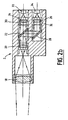
- the pyrometer of the invention is schematically illustrated on the figure 1 . It comprises an optical sensor or sensor 1 placed opposite a hot body, or in a gaseous medium, whose temperature is to be measured and which is connected to an optical block 2 via a single optical fiber 3.
- a detection circuit placed at the output of the optical block, or preferably integrated in this block, allows a conversion of the optical signals that it delivers into exploitable electrical signals by a processing unit 5 (after possibly conversion and adaptation by a conversion circuit 4) which then generates the value of the desired temperature.
- the configuration of the pyrometer presented is bichromatic, that is to say that the thermal radiation emitted by the surface of the hot body or the gas (the measuring probe then comprising a coating acting as a black micro-body) is measured on two spectral bands. distinct. It is thus possible to limit the causes of errors corresponding to the losses in transmissions and coupling of the radiation (curvatures, connectors, soiling) which directly affect the measurement in the case of a monochromatic analysis.
- a bichromatic structure requires separating the radiation coming out of the fiber in two parts. This is the object of the block optics 2 whose material structure is now described more precisely with regard to the figure 2a .
- This optical unit 2 comprises input input collimation means 20 for transmitting the radiation from the fiber 3 parallel to means for separating this beam into two parts constituted by a dichroic plate 22 which also acts as a filter transmission high pass and low pass in reflection. The beams leaving this plate are then directed, directly or via a mirror 28, to spectral selection means (red and blue spectra) comprising interference filters 30, 32. Output focusing means 24, 26 placed at the output of these filters make it possible to concentrate the separated radiations on quantum detectors 33, 34, preferably with gallium indium arsenide (In Ga As). The optical block thus produced is particularly compact and has high performance.
- the signal levels available at the input of the quantum detectors are higher than the signal levels that could be collected at the output of a separator cube and, secondly, the dichroic plate is not sensitive. to polarization and does not introduce aberrations in the event of possible poor convergence of the radiation.
- the gain on each of the luminous flux leaving the blade, relative to a device with separator cube, is 100%. It is thus possible either to use a fiber of smaller diameter for the measurement of the same temperature, or to extend the temperature range measured especially to low temperatures. It may be noted that in the case of spectral broadband measurements (300 to 400 nanometers), the interference filters 30, 32 may advantageously be omitted. It may also be noted that the use of achromatic optical doublets at the level of the focusing means also makes it possible to obtain an optimum spatial resolution allowing the use of detectors with a small surface area.
- the figure 2b shows a second embodiment of the optical block.
- the measurement can be performed directly from the optical unit 2 by providing it with means allowing a pyrometric aiming.
- These means comprise input focusing means 18 which capture the radiation and focus it at the focal point of the input collimating means 20, the light flux then going, as before, towards the separation means 22 and leading to the detectors 33. , 34.
- the electric currents delivered by the photovoltaic detectors are transformed into voltage and normalized in the current-voltage conversion circuit 4 which, for reasons of improvement of the signal / noise ratio, can advantageously be integrated into the optical unit.
- Vr red voltage
- Vb blue voltage
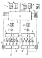
- this circuit comprises a simplified architecture both analog and digital particularly suitable for low measurement rates (of the order of 1000 measurements per second).
- this processing circuit comprises an entirely digital architecture organized around a digital microprocessor computing assembly 50 which receives the voltages Vr and Vb from the detectors and digitized by analog-to-digital converters 52, 54 and which delivers, after calculation, a value digital equal to the ratio Vr / Vb for storage means 56 which is extracted directly, as previously, the measured temperature T.
- a synchronization module 58 connected to the calculation unit 50 ensures the triggering of the measurement process under the control of a control software. management stored in a read-only memory 60 advantageously programmable and erasable (EPROM).
- EPROM programmable and erasable
- a display module 62 allows the display of the temperature T but also that of the ratio Vr / Vb.
- the converters have a resolution of 16 bits and have conversion times of the order of one microsecond.
- the ratio Vr / Vb is calculated in real time by the digital calculation unit 50 and is used as a pointer to extract the value of the temperature of the storage means which comprises as before a table of values (conversion table) giving the temperature T for each Vr / Vb ratio.
- Vr and Vb being the two color voltages (red and blue) delivered by the detectors and A and B two constants determined by a prior calibration.
- the signals Vr and Vb evolve in very important proportions whereas the ratio Vr / Vb remains on the contrary included in a rather reduced field which it is easy to cover entirely with a conversion table of reasonable size.
- a table having the input variable Vr / Vb as the input variable and the temperature output variable as an output variable are obtained. T and can be stored in a memory of 2048 words.
- the calculation of the ratio Vr / Vb is carried out at the level of the computing unit 50 which advantageously comprises a circuit specialized in the processing of the digital signals such as a signal processor (Digital Signal Processor) for example, which makes it possible to carry out operations on 48 or even 56 bits.
- a signal processor Digital Signal Processor
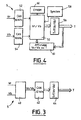
- the figure 5 shows a preferred embodiment of the processing circuit 5.
- the signals Vr and Vb from the two measuring channels and delivered by the detector circuits 33, 34 each constitute input signals for a fast analog-digital converter on the one hand 60a; 60b and secondly a multiplexer circuit a pathway to at least two channels (advantageously four channels) 62a; 62b each of whose outputs is connected to an amplification circuit 64a, 66a, 68a, 70a; 64b, 66b, 68b, 70b, each circuit having a distinct amplification factor (gain), preferably selected in the ratios 1, 4, 16, and 64.
- gain preferably selected in the ratios 1, 4, 16, and 64.
- the signals delivered by these amplification circuits are directed to a circuit demultiplexing at least two channels (advantageously four channels) to a channel 72a, 74b whose output is connected to a level adapter 74a; 74b which supplies an input voltage for an analog-to-digital converter 76a; 76b.
- the outputs of the two converters are connected to a digital processing unit, a signal processor 78, which manages and controls all the circuits of the processing circuit and generates the digital value T of the measured temperature.
- a digital-to-analog converter 80 may optionally provide this temperature in a form analog.
- the processing circuit 5 also includes, connected to the processor 78, a synchronization module 82, a data input and output assembly (in the form of a keyboard and a display) 84, a read-only memory 86 and a memory quick fast (flash type) 88.
- the measurement process is triggered by the synchronization module 82 under the control of a management software stored in the read-only memory 86 advantageously programmable and erasable (EPROM).
- EPROM programmable and erasable
- This process starts with a rapid but coarse conversion, for example on just 6 bits, performed by the fast converters 60a, 60b, in order to estimate the orders of magnitude of the color voltages Vr and Vb.
- the processor 78 determines the most suitable gain (1, 4, 16 or 64) on each of the two measurement channels (this determination is carried out in real time for each measurement point), thus enabling a reduction signal dynamics.
- the adaptation stage 74a, 74b makes it possible to calibrate the signals delivered by the amplification circuits selected to benefit from the totality of the resolution of the analog-digital converter 76a, 76b which preferably converts on at least 12 bits.
- the values of scanned Vr and Vb are used to calculate the ratio Vr / Vb executed by the arithmetic and logic processing unit of the processor 78.
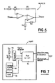
- FIG. figure 6 An exemplary embodiment of the gain amplification circuits 4, 16 or 64, the unit gain amplification circuit being conventionally produced by a simple operational amplifier mounted as a voltage follower, is illustrated on FIG. figure 6 .
- the input stage consists of an operational amplifier with field effect transistors (TEC) 90 for obtaining a very low offset current and little changing with the temperature.
- TEC field effect transistors
- the weakness of the bandwidth and the maximum rate of variation of its output voltage (slew-rate) of this amplifier to TEC is compensated by the presence at its output of a second operational amplifier with bipolar transistors 92 which has on the contrary a bandwidth and a very high slew-rate.
- the signal Ve from the multiplexer circuit 62a; 62b is directed to the non-inverting input of the first amplifier 90, its inverting input being connected to the midpoint of an adjustable potentiometer ⁇ R whose two ends are connected respectively to one end of a first resistor R1 whose other end is connected to the output of the second amplifier 92 and to one end of a second resistor R2 whose other end is connected to a positive reference potential.
- the output of the first amplifier constitutes the inverting input of the second amplifier whose non-inverting input is looped on the output of this second amplifier by a third resistor R3 and connected to a negative reference potential through a fourth resistor R4. .
- the synchronization module 58, 82 responsible for triggering the measurement process by activating the corresponding interrupt of the processor 50, 78 is represented on the figure 7 .
- This module comprises a four-channel multiplexer circuit to a channel 94 which receives respectively on each of its four inputs: an external signal, the output signals of two clock circuits 96, 98 of frequency 10 and 10000 Hz and the output signal a comparator 99 receiving at the input on the one hand the signal Vb and on the other hand a predetermined threshold voltage.
- the selection of one or the other of these signals is carried out from the signal processor 78 which thus generates four distinct synchronization modes: a slow mode for the calibration in which the constants A and B and the values of Vr and Vb are entered manually on the keyboard (in this mode, the measurement frequency is advantageously a few Hz, for example 10 Hz and the bandwidth on each channel is then limited) and three fast modes that differ by the triggering principle of the measurement .
- a slow mode for the calibration in which the constants A and B and the values of Vr and Vb are entered manually on the keyboard (in this mode, the measurement frequency is advantageously a few Hz, for example 10 Hz and the bandwidth on each channel is then limited) and three fast modes that differ by the triggering principle of the measurement .
- the temperature calculation is triggered by an external logic signal, which can then be executed up to 110,000 times per second.
- the calculation is triggered by the signal Vb as soon as it exceeds the predetermined threshold voltage.
- a fixed frequency synchronization mode the calculation is triggered
- the different frequencies mentioned above are given purely as an indication and it is possible, by modifying them, to adapt the pyrometer according to the invention to a very many situations.
- the pyrometer is capable of characterizing phenomena having natural periodicities (turbine blades for example) as processes having any prior variations.
- the processor waits, in a step 102, for an interruption signal that can be generated by the synchronization module 82 (temperature calculation function) or by the circuit 84 and display management (calibration function).
- the processor reads the voltage values Vr, Vb delivered by the fast converters 60a, 60b and, in step 106, it selects the gain best suited to the conversion. analog-digital it launches in a step 108. In parallel, in a step 110, it proceeds to calculate the ratio Vr / Vb (on the values resulting from the previous conversion). In the next step 112, it reads in the conversion table the value of the corresponding temperature and, in step 114, this value T is sent to a digital output or addressed to the converter 80 which delivers the analog equivalent t on its way out.
- step 116 the values Vr and Vb are read by the processor and saved for the next calculation and the gain is reset to 1 during the next step 118.
- the process either returns to the initial waiting state (step 102) or addresses the values of T and Vr / Vb to the management circuit of the display 84.
- the interruption results from the management circuit of the keyboard 84, an analysis of the message entered is carried out and the corresponding action is then executed. It can be a change of mode or a calibration with modification of the parameters A and B. This action is completed, the processor returns to its initial state of waiting for a new interruption coming from the keyboard or the synchronization module.
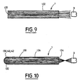
- FIGS. 9 and 10 illustrate two possible architectures for the measuring probe 1.
- these probes use a conventional optical fiber 120, without any focusing device, which is then placed opposite the surface whose temperature is to be measured, this surface being able to be temperature simply by moving a gas from the touch.
- a fiber is, for example, a multimode fiber with index jump in silica / silica (core / sheath).
- the transparent fiber is advantageously covered with a thin layer 122 of an opaque material which provides sufficient thermal and mechanical protection but specific to each application (deposition of a refractory material by plasma spraying, for example).
- the fiber-probe is connected to the transmission fiber 3 by a not shown connection.
- the probe is constituted by a cylindrical sapphire bar 130 whose radiation exposure face can be made in the form of a hemispherical cap 132 whose radius varies in a determined manner depending on the application considered. Of course, a simply perpendicular face can also be considered.
- the exit face of the sapphire facing the fiber is advantageously made in the form of a spherical cap 134 which allows a focusing of almost the entire flow to be conveyed in the fiber 3 (maximization of the optical coupling with the fiber) .
- This solution which avoids the use of a lens whose positioning is always delicate is particularly reliable given the small number of coins involved. It also has the advantage of low cost and that of maintaining the intrinsic qualities of the bar of sapphire.
- the outer surface of the bar has a thermal and mechanical protection 136.
- the hemispherical cap 132 is covered with various layers having for object to create at the free end of the sapphire a coating conferring a thermal emission of black body type.
- These layers whose total thickness does not exceed 10 to 15 ⁇ m (especially for obtaining a good temporal response) optimize on the one hand the emission and the thermal transfer and on the other hand thermomechanical behavior and chemical probe according to its environment (reducing or oxidizing medium).
- Each layer has a specific function; a first layer 138 highly emissive, and a second layer 142 opaque and highly conductive. Two layers are sufficient, however an intermediate layer 140 may be added to optimize the diffusion of heat and thus homogenize the temperature.
- This pyrometer can thus allow the knowledge of very complete experimental data on phenomena still little studied because out of reach of the classical instrumentation.
Landscapes
- Physics & Mathematics (AREA)
- General Physics & Mathematics (AREA)
- Spectroscopy & Molecular Physics (AREA)
- Radiation Pyrometers (AREA)
Description
La présente invention concerne un pyromètre permettant la réalisation de diagnostics thermiques (mesure de températures de gaz ou de surfaces en mouvement) en environnement sévère, avec une très grande rapidité de mesure.The present invention relates to a pyrometer for the realization of thermal diagnostics (measurement of gas temperatures or moving surfaces) in a severe environment, with a very high speed of measurement.
Ces conditions d'environnement extrême se trouvent notamment présentes lors des mesures de vitesses de rotation de turbines en fonctionnement, comme celles des turbomachines industrielles, des turbines d'hélicoptères, des turboréacteurs, ou des turbopompes d'alimentation de moteurs cryogéniques de fusées par exemple. Dans ces cas, seule une mesure optique est capable d'analyser le plus finement possible le comportement thermique de ces turbines et de permettre une connaissance précise des propriétés mécaniques des matériaux et de leur évolution en fonction de la température. L'article de Sam Walters "New instrumentation for advanced turbine research" publié dans la revue Mechanical Engineering de février 1983 (vol 105, n°2) décrit très exactement les problèmes posés par ces mesures et présente un bon aperçu des solutions existant actuellement.These extreme environmental conditions are particularly present during rotational speed measurements of turbines in operation, such as those of industrial turbomachines, helicopter turbines, turbojet engines, or cryopump engine power supply turbopumps, for example . In these cases, only an optical measurement is able to analyze as finely as possible the thermal behavior of these turbines and to allow a precise knowledge of the mechanical properties of materials and their evolution as a function of temperature. Sam Walters' article "New instrumentation for advanced turbine research" published in the Mechanical Engineering journal of February 1983 (Vol 105, No. 2) describes very precisely the problems posed by these measurements and presents a good overview of the existing solutions.
Ces solutions présentent cependant encore certains inconvénients. Des erreurs de mesure liées à des problèmes de transmission optique peuvent notamment exister dans des dispositifs utilisant une fibre optique monochromatique pour la capture et le transport du rayonnement thermique émis par la turbine en mouvement. Dans les dispositifs de mesure bichromatique dans lesquels il est nécessaire de procéder à la séparation du faisceau de lumière en sortie de la fibre de transport, il est classique de recourir à un cube séparateur du fait qu'il présente une grande homogénéité avec la fibre. Toutefois, un tel cube est particulièrement sensible aux vibrations et aux éventuels chocs et la répartition du flux lumineux à sa sortie peut alors s'en trouver modifiée. On connaît par la demande européenne
Par ailleurs, dans ces dispositifs bichromatiques, le traitement des signaux issus des moyens de séparation est généralement réalisé en temps réel sous une forme analogique à l'aide de composants discrets classiques. Il en résulte des temps de réponse importants (de l'ordre de la milliseconde) et, dans le cas de mesures à fréquences élevées, des contraintes de fonctionnement particulièrement importantes. Ainsi, la stabilisation du dispositif de mesure impose une limitation de la bande passante et en conséquence de la cadence (vitesse) globale de mesure. De même, du fait de sa structure, un tel dispositif reste sensible à tous les phénomènes de dérives en tension ou en température dont la suppression ne peut alors être envisagé qu'au prix de fréquents et fastidieux réglages.Moreover, in these bichromatic devices, the processing of the signals from the separation means is generally performed in real time in an analog form using conventional discrete components. This results in significant response times (of the order of a millisecond) and, in the case of measurements at high frequencies, particularly important operating constraints. Thus, the stabilization of the measuring device imposes a limitation of the bandwidth and consequently of the overall rate (speed) of measurement. Likewise, because of its structure, such a device remains sensitive to all phenomena of drift in voltage or temperature, the removal of which can then be considered only at the cost of frequent and tedious adjustments.
Enfin, la combinaison du système optique à cube séparateur et de l'ensemble électronique analogique précité ne permet pas d'aboutir à un dispositif miniaturisé dont le besoin est pourtant présent notamment dans les systèmes embarqués où un tel dispositif serait utile pour préciser les limites de fonctionnement de turbomoteurs et notamment le contrôle de leurs régimes transitoires.Finally, the combination of the splitter cube optical system and the aforementioned analog electronic assembly does not make it possible to achieve a miniaturized device whose need is however present in particular in embedded systems where such a device would be useful for clarifying the limits of operation of turbine engines and in particular the control of their transient conditions.
La présente invention a pour but de pallier les inconvénients précités et de proposer un pyromètre particulièrement compact et adapté à des cadences de détection rapides de telle sorte qu'il puisse effectuer de manière continue, dans une large plage de températures, des mesures instantanées de température notamment d'aubes de turbine en rotation.The present invention aims to overcome the aforementioned drawbacks and to provide a particularly compact pyrometer adapted to fast detection rates so that it can perform continuously, in a wide range of temperatures, instantaneous temperature measurements. in particular rotating turbine blades.
Ces buts sont atteints avec un pyromètre bichromatique rapide destiné à la mesure de la température T d'un gaz ou d'une surface en mouvement comportant:
- une sonde de mesure placée en regard de la surface ou immergée dans le gaz et captant un rayonnement thermique caractéristique de la température de cette surface ou de ce gaz,
- une fibre optique unique reliée à la sonde de mesure et transmettant ce rayonnement,
- un bloc optique recevant ce rayonnement et comprenant des moyens de collimation d'entrée pour transmettre ce rayonnement, des moyens de séparation formés d'une lame dichroïque pour séparer le rayonnement transmis selon deux bandes de spectrales distinctes, et des moyens de focalisation de sortie pour concentrer les rayonnements séparés,
- un circuit de détection quantique recevant ces rayonnements séparés et assurant leur conversion en deux tensions de couleur Vr, Vb,
- un circuit de traitement recevant ces signaux de tension et comprenant des moyens de conversion analogique-numérique, un processeur de traitement du signal (DSP) calculant à partir de ces valeurs numériques un rapport Vr/Vb et des moyens de mémorisation munis d'une table de valeurs prédéterminées par étalonnage T= f(Vr/Vb) et délivrant en sortie, à partir du rapport calculé, la température T de la surface ou du gaz, le circuit de traitement comportant en outre des moyens de conversion rapide des valeurs Vr et Vb afin d'estimer leur ordre de grandeur et des moyens d'adaptation du niveau d'amplification des signaux Vr et Vb selon les ordres de grandeur délivrés au processeur par les moyens de conversion rapide.
- a measuring probe placed facing the surface or immersed in the gas and capturing a thermal radiation characteristic of the temperature of this surface or of this gas,
- a single optical fiber connected to the measurement probe and transmitting this radiation,
- an optical unit receiving this radiation and comprising input collimation means for transmitting this radiation, separation means formed of a dichroic plate for separating the transmitted radiation in two distinct spectral bands, and output focusing means for to concentrate the separated radiations,
- a quantum detection circuit receiving these separated radiations and ensuring their conversion into two color voltages Vr, Vb,
- a processing circuit receiving these voltage signals and comprising analog-to-digital conversion means, a signal processing processor (DSP) calculating from these digital values a Vr / Vb ratio and storage means provided with a table of predetermined values by calibration T = f (Vr / Vb) and outputting, from the calculated ratio, the temperature T of the surface or gas, the processing circuit further comprising means for rapid conversion of the values Vr and Vb in order to estimate their order of magnitude and means for adapting the amplification level of the signals Vr and Vb according to the orders of magnitude delivered to the processor by the fast conversion means.
La structure ainsi définie aboutit à l'obtention d'un pyromètre particulièrement compact, avec l'emploi d'une lame dichroïque comme dispositif séparateur, et rapide, par le recours à un processeur de signal combiné avec une mémoire rapide contenant une table de conversion préétablie, permettant notamment la mesure instantanée de la température d'aubes de turbine en rotation.The structure thus defined results in obtaining a particularly compact pyrometer, with the use of a dichroic blade as a separator device, and fast, by the use of a signal processor combined with a fast memory containing a conversion table. pre-established, in particular allowing the instantaneous measurement of the temperature of rotating turbine blades.
Pour certaines applications, le déport de la mesure n'est pas indispensable et la mesure peut être faite directement à partir du bloc optique qui sera alors avantageusement muni de moyens de focalisation du rayonnement émis par la surface.For some applications, the offset of the measurement is not essential and the measurement can be made directly from the optical block which will then be advantageously provided with means for focusing the radiation emitted by the surface.
Les mesures peuvent être réalisées depuis de larges bandes spectrales jusqu'à des domaines monochromatiques où il est nécessaire que chacun des moyens de focalisation de sortie des rayonnements séparés soit précédé par des moyens de filtrage interférentiels.Measurements can be made from wide spectral bands to monochromatic domains where it is necessary for each of the separate radiation output focusing means to be preceded by interference filtering means.
De préférence, les moyens de focalisation comportent des doubles achromatiques.Preferably, the focusing means comprise achromatic doubles.
Les moyens de conversion rapide comprennent avantageusement deux convertisseurs analogique-numérique de type flash. Les moyens d'adaptation du niveau d'amplification comprennent, de préférence pour chaque signal Vr ou Vb, un circuit multiplexeur une voie vers au moins deux voies recevant le signal et le délivrant à l'un de au moins deux circuits d'amplification de gain différent dont les sorties sont reliées à un circuit démultiplexeur de deux voies au moins vers une voie, un seul des circuits d'amplification étant sélectionné à chaque calcul du rapport Vr/Vb. Le circuit de traitement peut aussi comporter des moyens de conversion numérique-analogique placés en sortie du processeur de signal et destinés à obtenir une valeur analogique de la température mesurée.The fast conversion means advantageously comprise two analog-to-digital converters of the flash type. The means for adapting the amplification level comprise, preferably for each signal Vr or Vb, a multiplexer circuit a pathway to at least two channels receiving the signal and delivering it to one of at least two amplification circuits. different gain whose outputs are connected to a demultiplexer circuit of at least two channels to a channel, only one of the amplification circuits being selected at each calculation of the Vr / Vb ratio. The processing circuit may also include digital-to-analog conversion means placed at the output of the signal processor and intended to obtain an analog value of the measured temperature.
Le circuit de détection comporte deux détecteurs quantiques du type InGaAs. Ces détecteurs transforment le rayonnement qu'ils reçoivent en un courant électrique proportionnel à la puissance de ce rayonnement.The detection circuit comprises two quantic detectors of the InGaAs type. These detectors transform the radiation they receive into an electric current proportional to the power of this radiation.
Les moyens de mémorisation comprennent une mémoire rapide de type flash qui est bien adaptée à un processeur de type DSP.The storage means comprise a flash-type fast memory which is well adapted to a DSP-type processor.
Le circuit de traitement numérique peut être remplacé par un circuit comportant un diviseur analogique recevant les signaux Vr et Vb et délivrant le rapport Vr/Vb pour un convertisseur analogique-numérique dont la sortie est reliée à un circuit mémoire comprenant une table de valeur T=f(Vr/Vb) et délivrant la température T mesurée.The digital processing circuit may be replaced by a circuit comprising an analog divider receiving the signals Vr and Vb and delivering the ratio Vr / Vb for an analog-digital converter whose output is connected to a memory circuit comprising a table of value T = f (Vr / Vb) and delivering the measured temperature T.
La sonde de mesure comporte un barreau de saphir recouvert d'une fine couche protectrice et dont l'extrémité en regard de la fibre comporte une calotte sphérique focalisant dans la fibre la quasi totalité du rayonnement émis. L'autre extrémité de la sonde de mesure recevant le rayonnement peut comporter une calotte hémisphérique dont le rayon est déterminé selon la distance à la surface.The measuring probe comprises a sapphire bar covered with a thin protective layer and whose end facing the fiber has a spherical cap focusing in the fiber almost all radiation emitted. The other end of the measuring probe receiving the radiation may comprise a hemispherical cap whose radius is determined according to the distance to the surface.
Dans le cas particulier de la mesure des gaz, l'extrémité de la sonde de mesure est recouverte d'un revêtement conférant une émission thermique de type corps noir. Ce revêtement est constitué d'une première couche fortement émissive, et d'une deuxième couche opaque à la lumière et fortement conductrice. Il peut également être pourvu d'une couche intermédiaire placée entre les première et seconde couches et assurant une optimisation de la diffusion de la chaleur et une homogénéisation de la température. Si ces couches optimisent l'émission et le transfert thermique, elles permettent également d'assurer la tenue thermomécanique et chimique de la sonde en fonction de son environnement (milieu réducteur ou oxydant).In the particular case of the measurement of gases, the end of the measuring probe is covered with a coating conferring a thermal emission of black body type. This coating consists of a first highly emissive layer, and a second layer opaque to light and strongly conductive. It can also be provided with an intermediate layer placed between the first and second layers and ensuring optimization of the heat diffusion and homogenization of the temperature. If these layers optimize the emission and the heat transfer, they also make it possible to ensure the thermomechanical and chemical resistance of the probe according to its environment (reducing or oxidizing medium).
La présente invention concerne également un procédé de mesure de température d'un gaz ou d'une surface en mouvement par la détermination et le traitement d'un rayonnement thermique caractéristique de cette surface ou de ce gaz utilisant le pyromètre bichromatique précité et comportant les étapes suivantes:
- 1) capter un rayonnement thermique caractéristique de la témpérature de la surface ou du gaz,
- 2) séparer ce rayonnement en deux rayonnements de bandes de spectrales distinctes,
- 3) convertir ces deux rayonnements en deux tensions de couleur Vr et Vb,
- 4) estimer les ordres de grandeur des tensions de couleur Vr et vb afin d'adapter le gain d'un circuit d'amplification de ces tensions,
- 5) calculer leur rapport Vr/Vb, et
- 6) extraire la valeur correspondante de la température T mesurée d'une table de conversion T=f(Vr/Vb) déterminée préalablement par étalonnage.
- 1) capture a thermal radiation characteristic of the temperature of the surface or gas,
- 2) to separate this radiation into two radiations of distinct spectral bands,
- 3) converting these two radiations into two color voltages Vr and Vb,
- 4) estimate the orders of magnitude of the color voltages Vr and vb in order to adapt the gain of an amplification circuit of these voltages,
- 5) calculate their ratio Vr / Vb, and
- 6) extracting the corresponding value of the measured temperature T from a conversion table T = f (Vr / Vb) previously determined by calibration.
D'autres caractéristiques et avantages de la présente invention ressortiront mieux de la description suivante, faite à titre indicatif et non limitatif, en regard des dessins annexés, sur lesquels:
- la
figure 1 est un schéma de principe du pyromètre rapide selon l'invention, - les
figures 2a et2b montrent deux exemples de réalisation du bloc optique utilisé dans le pyromètre de lafigure 1 , - la
figure 3 montre un premier exemple de réalisation de l'ensemble de traitement des signaux mis en oeuvre dans le pyromètre de lafigure 1 , - la
figure 4 montre un second exemple de réalisation de l'ensemble de traitement des signaux mis en oeuvre dans le pyromètre de lafigure 1 , - la
figure 5 montre un exemple préférentiel de réalisation de l'ensemble de traitement des signaux mis en oeuvre dans le pyromètre de lafigure 1 , - la
figure 6 illustre un premier détail de réalisation de l'ensemble de lafigure 5 , - la
figure 7 illustre un second détail de réalisation de l'ensemble de lafigure 5 , - la
figure 8 est un organigramme montrant le fonctionnement de l'ensemble de traitement des signaux de lafigure 5 , et - les
figures 9 et 10 illustrent des exemples de réalisation de sondes pouvant être utilisés dans le pyromètre de lafigure 1 .
- the
figure 1 is a schematic diagram of the fast pyrometer according to the invention, - the
Figures 2a and2b show two examples of realization of the optical block used in the pyrometer of thefigure 1 , - the
figure 3 shows a first embodiment of the signal processing assembly implemented in the pyrometer of thefigure 1 , - the
figure 4 shows a second embodiment of the signal processing assembly implemented in the pyrometer of thefigure 1 , - the
figure 5 shows a preferred embodiment of the signal processing assembly implemented in the pyrometer of thefigure 1 , - the
figure 6 illustrates a first detail of realization of the whole of thefigure 5 , - the
figure 7 illustrates a second detail of realization of the whole of thefigure 5 , - the
figure 8 is a flowchart showing the operation of the signal processing set of thefigure 5 , and - the
Figures 9 and 10 illustrate examples of embodiments of probes that can be used in the pyrometer of thefigure 1 .
Le pyromètre de l'invention est illustré schématiquement sur la
La configuration du pyromètre présenté est bichromatique, c'est à dire que le rayonnement thermique émis par la surface du corps chaud ou le gaz (la sonde de mesure comportant alors un revêtement faisant office de micro-corps noir) est mesuré sur deux bandes spectrales distinctes. Il est ainsi possible de limiter les causes d'erreurs correspondant aux pertes en transmissions et couplage du rayonnement (courbures, connectiques, salissures) qui affectent directement la mesure dans le cas d'une analyse monochromatique. Par contre, une structure bichromatique exige de séparer le rayonnement sortant de la fibre en deux parties. C'est l'objet du bloc optique 2 dont la structure matérielle est maintenant décrite plus précisément en regard de la
Ce bloc optique 2 comporte en entrée des moyens de collimation d'entrée 20 destinés à transmettre parallèlement le rayonnement issu de la fibre 3 vers des moyens de séparation de ce faisceau en deux parties constitués par une lame dichroïque 22 qui joue également un rôle de filtre passe-haut en transmission et passe-bas en réflexion. Les faisceaux quittant cette lame sont ensuite dirigés, directement ou par l'intermédiaire d'un miroir 28, vers des moyens de sélection spectrale (spectres rouge et bleu) comprenant des filtres interférentiels 30, 32. Des moyens de focalisation de sortie 24, 26 placés en sortie de ces filtres permettent de concentrer les rayonnements séparés sur des détecteurs quantiques 33, 34, de préférence à arséniure de gallium indium (In Ga As). Le bloc optique ainsi réalisé est particulièrement compact et présente des performances élevées. En effet, d'une part les niveaux de signal disponibles en entrée des détecteurs quantiques (photovoltaïques) sont supérieurs aux niveaux de signal qui pourraient être recueillis en sortie d'un cube séparateur et d'autre part la lame dichroïque n'est pas sensible à la polarisation et n'introduit pas d'aberrations en cas d'éventuelle mauvaise convergence du rayonnement. Le gain sur chacun des flux lumineux quittant la lame, par rapport à un dispositif avec cube séparateur, est de 100%. Il est ainsi possible soit d'utiliser une fibre de plus faible diamètre pour la mesure d'une même température, soit d'étendre la plage de température mesurée notamment vers les basses températures. Il peut être noté que dans le cas de mesures à large bande spectrale (300 à 400 nanomètres), les filtres interférentiels 30, 32 peuvent avantageusement être omis. Il peut aussi être noté que l'utilisation de doublets optiques achromatiques au niveau des moyens de focalisation permet de plus d'obtenir une résolution spatiale optimum autorisant le recours à des détecteurs à faible surface.This
La
Les courants électriques délivrés par les détecteurs photovoltaïques sont transformés en tension et normalisés dans le circuit de conversion courant-tension 4 qui pour des raisons d'amélioration du rapport signal/bruit peut avantageusement être intégré au bloc optique.The electric currents delivered by the photovoltaic detectors are transformed into voltage and normalized in the current-
Les tensions de couleur délivrées par ce circuit au niveau de chacune des deux voies de mesure seront référencées Vr (tension de rouge) et Vb (tension de bleu).The color voltages delivered by this circuit at each of the two measurement channels will be referenced Vr (red voltage) and Vb (blue voltage).
Le traitement des signaux Vr et Vb à partir desquels la température T à mesurer est déterminée est effectué dans le circuit de traitement 5 dont différents exemples de réalisation sont montrés aux
Sur la
Au contraire, sur la
Afin de permettre des cadences de mesure très rapides (jusqu'à 110 000 mesures par seconde), les convertisseurs ont une résolution de 16 bits et comportent des temps de conversion de l'ordre de la microseconde. Le rapport Vr/Vb est calculé en temps réel par l'ensemble de calcul numérique 50 et est utilisé comme pointeur pour extraire la valeur de la température des moyens de mémorisation qui comporte comme précédemment une table de valeurs (table de conversion) donnant la température T pour chaque rapport de Vr/Vb.To enable very fast measurement rates (up to 110,000 measurements per second), the converters have a resolution of 16 bits and have conversion times of the order of one microsecond. The ratio Vr / Vb is calculated in real time by the
Dans le cas du pyromètre bichromatique de l'invention, la valeur de la température est donnée par la formule suivante: ![]()
![]()
Vr et Vb étant les deux tensions de couleur (rouge et bleu) délivrées par les détecteurs et A et B deux constantes déterminées par un étalonnage préalable.Vr and Vb being the two color voltages (red and blue) delivered by the detectors and A and B two constants determined by a prior calibration.
Or, le calcul en temps réel de T à partir de Vr et Vb, s'il ne présente pas de difficultés particulières pour des cadences de mesure faibles et peut être réalisé par une technologie classique analogique ou numérique, devient un réel problème quant il s'agit de l'effectuer à des cadences plus importantes. En effet, les techniques analogiques deviennent très complexes au delà d'un temps de réponse de 1 ms et demandent le recours à des circuits spéciaux qui s'avèrent très sensibles d'utilisation. Quant aux techniques numériques, le calcul d'un logarithme voire la réalisation de plusieurs divisions demandent des temps d'exécution conséquents qui s'avèrent incompatibles avec des cadences de mesure très élevées.However, the real-time calculation of T from Vr and Vb, if it does not present any particular difficulties for low measurement rates and can be achieved by a conventional analog or digital technology, becomes a real problem when it is used. is to perform it at higher rates. Indeed, analog techniques become very complex beyond a response time of 1 ms and require the use of special circuits that are very sensitive to use. As for the numerical techniques, the computation of a logarithm even the realization of several divisions require substantial execution times which are incompatible with very high measurement rates.
Aussi, la présente invention a résolu ce problème en ayant recours à la table de conversion T= f(Vr/Vb) comportant un ensemble de valeurs déterminées préalablement et remises à jour à chaque modification des constantes A et B obtenues lors d'étalonnages. En effet, les signaux Vr et Vb évoluent dans des proportions très importantes alors que le rapport Vr/Vb reste au contraire inclus dans un domaine assez réduit qu'il est facile de couvrir entièrement avec une table de conversion de taille raisonnable. Ainsi, en prenant toutes les valeurs du rapport Vr/Vb comprises entre 0,3 et 2,6 par pas de 10-3, on obtient une table ayant comme variable d'entrée le rapport Vr/Vb et comme variable de sortie la température T et pouvant être emmagasinée dans une mémoire de 2048 mots. Le processus de mesure de la température se résume alors au simple calcul du rapport des tensions de couleur Vr/Vb et au pointage dans une mémoire contenant cette table de conversion de la valeur de la température correspondante. Bien évidemment, cette solution originale peut aussi être employée pour des cadences plus faibles comme l'a montré l'exemple de réalisation de la
Le calcul du rapport Vr/Vb est effectué au niveau de l'ensemble de calcul 50 qui comporte avantageusement un circuit spécialisé dans le traitement des signaux numériques comme un processeur de signal (Digital Signal Processor) par exemple, lequel permet d'effectuer des opérations sur 48 voire 56 bits.The calculation of the ratio Vr / Vb is carried out at the level of the
La
Le déclenchement du processus de mesure est assuré par le module de synchronisation 82 sous la commande d'un logiciel de gestion emmagasiné dans la mémoire morte 86 avantageusement programmable et effaçable (EPROM). Ce processus débute par une conversion rapide mais grossière, par exemple sur simplement 6 bits, réalisée par les convertisseurs rapides 60a, 60b, afin d'estimer les ordres de grandeur des tensions de couleur Vr et Vb. A partir des valeurs obtenues, le processeur 78 détermine le gain le plus adapté (1, 4, 16 ou 64) sur chacune des deux voies de mesure (cette détermination est effectuée en temps réel pour chaque point de mesure), permettant ainsi une réduction de la dynamique des signaux. L'étage d'adaptation 74a, 74b permet de calibrer les signaux délivrés par les circuits d'amplification sélectionnés pour bénéficier de la totalité de la résolution du convertisseur analogique-numérique 76a, 76b qui effectue la conversion de préférence sur au moins 12 bits. Les valeurs de Vr et Vb numérisées servent au calcul du rapport Vr/Vb exécuté par l'unité de traitement arithmétique et logique du processeur 78.The measurement process is triggered by the
Un exemple de réalisation des circuits d'amplification de gain 4, 16 ou 64, le circuit d'amplification de gain unité étant réalisé classiquement par un simple amplificateur opérationnel monté en suiveur de tension, est illustré sur la
Le module de synchronisation 58, 82 chargé de déclencher le processus de mesure par l'activation de l'interruption correspondante du processeur 50, 78 est représenté sur la
Les différentes étapes de calcul de la température à partir des tensions de couleur Vr et Vb sont maintenant décrites en regard de la
Après une initialisation réalisée dans une première étape 100, le processeur se met en attente, dans une étape 102, d'un signal d'interruption qui peut être généré par le module de synchronisation 82 (fonction calcul de la température) ou par le circuit de gestion de l'affichage et du clavier 84 (fonction étalonnage).After an initialization performed in a
Lorsque cette interruption résulte du module de synchronisation, dans une étape 104, le processeur lit les valeurs de tension Vr, Vb délivrées par les convertisseurs rapides 60a, 60b puis, à l'étape 106, il sélectionne le gain le mieux adapté à la conversion analogique-numérique qu'il lance dans une étape 108. Parallèlement, dans une étape 110, il procède au calcul du rapport Vr/Vb (sur les valeurs résultant de la conversion précédente). A l'étape suivante 112, il lit dans la table de conversion la valeur de la température correspondante et, dans l'étape 114, cette valeur T est envoyée sur une sortie numérique ou adressée au convertisseur 80 qui en délivre l'équivalent analogique t sur sa sortie. A la fin de la conversion, à l'étape 116, les valeurs Vr et Vb sont lues par le processeur et sauvegardées pour le calcul à venir et le gain est remis à 1 durant l'étape suivante 118. Selon le mode de fonctionnement sélectionné à l'étape 120 (mode calcul/mode étalonnage), le processus soit revient dans l'état d'attente initial (étape 102) soit adresse les valeurs de T et de Vr/Vb au circuit de gestion de l'affichage 84.When this interruption results from the synchronization module, in a
Au contraire, si l'interruption résulte du circuit de gestion du clavier 84, il est procédé à une analyse du message entré et l'action correspondante est ensuite exécutée. Il peut s'agir d'un changement de mode ou bien d'un étalonnage avec modification des paramètres A et B. Cette action terminée, le processeur revient dans son état initial d'attente d'une nouvelle interruption en provenance du clavier ou du module de synchronisation.On the contrary, if the interruption results from the management circuit of the
Les
En outre, dans la version représentée sur la
Le pyromètre bichromatique rapide selon l'invention est susceptible d'être utilisé dans toutes les étapes de développement et d'exploitation des turbomoteurs:
- en phase de développement, la connaissance des températures d'aubes permet par exemple d'étudier les échanges entre le gaz et la turbine ou les différentes méthodes de refroidissement, et
- en phase de fonctionnement, la détection d'anomalie est facilitée par le suivi précis de l'évolution de la température.
- in the development phase, the knowledge of the blade temperatures makes it possible, for example, to study the exchanges between the gas and the turbine or the various cooling methods, and
- in the operating phase, the anomaly detection is facilitated by the precise monitoring of the evolution of the temperature.
Sa rapidité le prédispose en outre pour un emploi dans de nombreux secteurs de pointe. Par exemple, la mesure de particules en mouvement rapide dans des écoulements gazeux tels que des lits fluidisés ou des jets plasmas. Par exemple encore, les traitement de surfaces par irradiations très brèves à l'aide de faisceaux intenses (laser, rayonnement solaire concentré,...).Its speed also predisposes it for employment in many leading sectors. For example, the measurement of rapidly moving particles in gaseous flows such as fluidized beds or plasma jets. For example, surface treatment by very short irradiations using intense beams (laser, concentrated solar radiation, etc.).
Ce pyromètre peut donc permettre la connaissance de données expérimentales très complètes sur des phénomènes encore peu étudiés car hors de portée de l'instrumentation classique.This pyrometer can thus allow the knowledge of very complete experimental data on phenomena still little studied because out of reach of the classical instrumentation.
Claims (16)
- A fast bichromatic pyrometer for measuring the temperature T of a gas or of a moving surface, the pyrometer comprising:· a measurement probe (1) placed facing the surface or immersed in the gas and picking up thermal radiation that is characteristic of the temperature of said surface or of said gas;· a single optical fibre (3) connected to the measurement probe and transmitting said radiation;· an optical block (2) connected to the optical fibre and receiving said radiation, the optical block including inlet collimation means (20) for transmitting all of said radiation, separation means formed by a dichroic slide (22) for separating the transmitted radiation into two distinct spectral bands, and outlet focusing means (24, 26) for concentrating the separated bands of radiation;· a quantum detection circuit (2, 4) receiving said separated bands of radiation and converting them into two colour voltages Vr, Vb; and· a treatment circuit (5) receiving the voltage signals and including analog-to-digital conversion means (52, 54; 76a, 76b), a digital signal processor (DSP 50, 78) for calculating the ratio Vr/Vb from these digital values, and memory means (56, 88) provided with a table of predetermined values of T = f(Vr/Vb) as obtained by calibration and delivering at its output, on the basis of the calculated ratio, the temperature T of the surface or of the gas, the treatment circuit (5) further including fast conversion means (60a, 60b) for converging the values Vr and Vb so as to estimate their orders of magnitude and means for matching the amplification levels of the signals Vr and Vb as a function of the orders of magnitude delivered to the processor by the fast conversion means.
- A fast bichromatic pyrometer for measuring the temperature T of a surface and comprising:· an optical block (2) placed facing the surface, picking up thermal radiation emitted by said surface and characteristic of its temperature, and comprising inlet focusing means (18) that receive the emitted radiation and focus it on the focus of inlet collimation means (20) for transmitting all of the received radiation, separation means formed by a dichroic slide (22) for separating said radiation into two distinct spectral bands, and outlet focusing means (24, 26) for concentrating the separated bands of radiation;· a quantum detection circuit (2, 4) receiving said separated bands of radiation and converting them into two colour voltages Vr, Vb; and· a treatment circuit (5) receiving the voltage signals and including analog-to-digital conversion means (52, 54; 76, 76b), a digital signal processor (DSP 50, 78) for calculating the ratio Vr/Vb from these digital values, and memory means (56, 88) provided with a table of predetermined values of T = f(Vr/Vb) as obtained by calibration and delivering at its output, on the basis of the calculated ratio, the temperature T of the surface, the treatment circuit (5) further including fast conversion means (60a, 60b) for converging the values Vr and Vb so as to estimate their orders of magnitude and means for matching the amplification levels of the signals Vr and Vb as a function of the orders of magnitude delivered to the processor by the fast conversion means.
- A fast bichromatic pyrometer according to claim 1 or claim 2, characterised in that each of the outlet focusing means (24, 26) for the separated bands of radiation is preceded by interference filter means (30, 32).
- A fast bichromatic pyrometer according to claim 1 or claim 2, characterised in that the focusing means (18, 24, 26) comprise achromatic doublets.
- A fast bichromatic pyrometer according to claim 1 or claim 2, characterised in that the fast conversion means comprise two flash type analog-to-digital converters.
- A fast bichromatic pyrometer according to claim 1 or claim 2, characterised in that the means for adapting the amplification levels comprise, for each signal Vr or Vb, a multiplexer circuit having one input and at least two outputs (62a; 62b) receiving the signal and delivering it to one of at least two amplification circuits of different gains (64a, 66a, 68a, 70a; 64b, 66b, 68b, 70b) whose outputs are connected to a multiplexer circuit having at least two inputs and one output (72a; 72b), a single amplification circuit being selected for each calculation of the ratio Vr/Vb.
- A fast bichromatic pyrometer according claim 1 or claim 2, characterised in that the treatment circuit (5) further includes digital-to-analog conversion means (80) placed at the output from the signal processor and designed to obtain an analog value of the measured temperature.
- A fast bichromatic pyrometer according claim 1 or claim 2, characterised in that the detection circuit includes two quantum detectors (33, 34) of the InGaAs type.
- A fast bichromatic pyrometer according to claim 1 or claim 2, characterised in that the memory means comprise a flash type fast memory.
- A fast bichromatic pyrometer according to claim 1 or claim 2, characterised in that the treatment circuit (5) is replaced by a circuit comprising an analog divider (40) receiving the signals Vr and Vb and delivering the ratio Vr/Vb to an analog-to-digital converter (42) whose output is connected to a memory circuit (44) that contains a table of values T = f(Vr/Vb) and that delivers the measured temperature T.
- A fast bichromatic pyrometer according to claim 1, characterised in that the measurement probe comprises a sapphire bar (130) covered in a fine protective layer (136) and whose end facing the fibre (3) includes a spherical cap (134) focusing substantially all of the emitted radiation into the fibre.
- A fast bichromatic pyrometer according to claim 1, characterised in that the end of the measurement probe that receives radiation from the surface includes a hemispherical cap (132) whose radius is determined as a function of the distance to the surface.
- A fast bichromatic pyrometer according claim 1 or claim 12, more particularly intended for measuring the temperature of gases, characterised in that the end of the measurement probe that receives the radiation is covered in a coating which confers black body type thermal emission thereto.
- A fast bichromatic pyrometer according claim 13 characterised in that said coating is constituted by a first layer (138) that is highly emissive and by a second layer (142) that is opaque to light and that is highly conductive.
- A fast bichromatic pyrometer according claim 14 characterised in that the coating further includes an intermediate layer (140) placed between the first and second layers (138, 142) and optimising heat diffusion and making temperature uniform.
- A method of measuring the temperature of a gas or of a moving surface by determining and treating thermal radiation characteristic of the temperature of said surface or of said gas which uses the fast bichromatic pyrometer according claim 1, the method comprising the following steps:1) picking up thermal radiation characteristic of the temperature of the surface or of the gas;2) separating said radiation into two distinct spectrum bands of radiation;3) converting the two bands of radiation into two colour voltages Vr and Vb;4) estimating the orders of magnitude of colour voltages Vr and Vb in order to match the gain of an amplification circuit for said voltages;5) calculating the ratio thereof Vr/Vb; and6) extracting the corresponding value of the measured temperature T from a conversion table T = f(Vr/Vb) that has previously been determined by calibration.
Applications Claiming Priority (2)
| Application Number | Priority Date | Filing Date | Title |
|---|---|---|---|
| FR9412588A FR2726081B1 (en) | 1994-10-21 | 1994-10-21 | FAST OPTICAL FIBER BICHROMATIC PYROMETER |
| FR9412588 | 1994-10-21 |
Publications (3)
| Publication Number | Publication Date |
|---|---|
| EP0708317A1 EP0708317A1 (en) | 1996-04-24 |
| EP0708317B1 EP0708317B1 (en) | 2002-01-30 |
| EP0708317B2 true EP0708317B2 (en) | 2010-06-09 |
Family
ID=9468078
Family Applications (1)
| Application Number | Title | Priority Date | Filing Date |
|---|---|---|---|
| EP95402286A Expired - Lifetime EP0708317B2 (en) | 1994-10-21 | 1995-10-13 | Rapid fiberoptic bichromatic pyrometer |
Country Status (5)
| Country | Link |
|---|---|
| US (1) | US5755510A (en) |
| EP (1) | EP0708317B2 (en) |
| DE (1) | DE69525212T3 (en) |
| ES (1) | ES2171514T5 (en) |
| FR (1) | FR2726081B1 (en) |
Cited By (1)
| Publication number | Priority date | Publication date | Assignee | Title |
|---|---|---|---|---|
| DE102011016102A1 (en) * | 2011-01-07 | 2012-07-12 | Heraeus Noblelight Gmbh | Method for determining the infrared radiation |
Families Citing this family (19)
| Publication number | Priority date | Publication date | Assignee | Title |
|---|---|---|---|---|
| FR2773878B1 (en) * | 1998-01-20 | 2000-04-07 | Auxitrol Sa | TEMPERATURE MEASUREMENT SENSOR |
| FR2773879B1 (en) * | 1998-01-20 | 2001-01-26 | Auxitrol Sa | TEMPERATURE MEASUREMENT SENSOR |
| US6373562B1 (en) * | 1998-10-09 | 2002-04-16 | Kim A. Marsh | Fiberoptic cable tester |
| US6151446A (en) * | 1999-07-06 | 2000-11-21 | Applied Materials, Inc. | Apparatus and method for thermally processing substrates including a processor using multiple detection signals |
| US7690840B2 (en) * | 1999-12-22 | 2010-04-06 | Siemens Energy, Inc. | Method and apparatus for measuring on-line failure of turbine thermal barrier coatings |
| GB0000954D0 (en) * | 2000-01-18 | 2000-03-08 | Renishaw Plc | Spectroscopic probe |
| US6698920B1 (en) * | 2000-05-08 | 2004-03-02 | General Electric Company | Temperature measuring system and optical switch used therein |
| US6786634B2 (en) * | 2001-10-10 | 2004-09-07 | Noritake Co., Limited | Temperature measuring method and apparatus |
| US20040179575A1 (en) * | 2003-01-23 | 2004-09-16 | Markham James R. | Instrument for temperature and condition monitoring of advanced turbine blades |
| US7075629B2 (en) * | 2003-05-12 | 2006-07-11 | Honeywell International Inc. | High temperature pyrometer |
| US7826954B2 (en) * | 2004-06-25 | 2010-11-02 | Honda Motor Co., Ltd. | System for monitoring sensor outputs of a gas turbine engine |
| US7432505B2 (en) * | 2006-05-04 | 2008-10-07 | Siemens Power Generation, Inc. | Infrared-based method and apparatus for online detection of cracks in steam turbine components |
| US7633066B2 (en) * | 2006-05-22 | 2009-12-15 | General Electric Company | Multiwavelength pyrometry systems |
| US8790006B2 (en) * | 2009-11-30 | 2014-07-29 | General Electric Company | Multiwavelength thermometer |
| US20120230366A1 (en) * | 2011-03-10 | 2012-09-13 | Yaosheng Chen | Optical Digital Thermometer |
| DE102012011924B3 (en) * | 2012-06-15 | 2013-11-21 | Keller Hcw Gmbh | Method for contactless temperature measurement of moving elongate measuring object e.g. liquid metal melt casting beam, involves displaying relative proportional signal strength value for adjusting pyrometer |
| US11215508B2 (en) * | 2019-02-01 | 2022-01-04 | Solar Turbines Incorporated | Temperature measuring system |
| CN110455417B (en) * | 2019-08-21 | 2020-08-04 | 北京环境特性研究所 | Quantitative measurement error correction method for stray radiation of infrared optical system |
| US12487124B2 (en) * | 2022-01-31 | 2025-12-02 | General Electric Company | Systems and methods for measuring temperature |
Citations (4)
| Publication number | Priority date | Publication date | Assignee | Title |
|---|---|---|---|---|
| DE1648233A1 (en) † | 1967-04-18 | 1972-01-13 | Inst Metallurg Im A A Bajkowa | Method and device for measuring true body temperature after exposure |
| DE3202089C2 (en) † | 1982-01-23 | 1985-01-17 | Fa. Carl Zeiss, 7920 Heidenheim | Fiber optic temperature sensor |
| DE2755713C2 (en) † | 1976-12-16 | 1987-06-25 | Luxtron Corp., Mountain View, Calif., Us | |
| US5021980A (en) † | 1989-02-21 | 1991-06-04 | Lsi Logic Corporation | Remote measurement of temperature |
Family Cites Families (14)
| Publication number | Priority date | Publication date | Assignee | Title |
|---|---|---|---|---|
| US3922550A (en) * | 1973-12-28 | 1975-11-25 | Raytheon Co | Radiometric system |
| DE2405651B2 (en) * | 1974-02-04 | 1980-08-14 | Mannesmann Ag, 4000 Duesseldorf | pyrometer |
| GB1602160A (en) * | 1978-04-26 | 1981-11-11 | Negretti & Zambra Aviat Ltd | Pyrometers |
| GB2068109B (en) * | 1980-01-21 | 1984-05-23 | Europ Electronic Syst Ltd | Monitoring strip temperature |
| GB8416201D0 (en) * | 1984-06-26 | 1984-08-01 | Land Infrared Ltd | Temperature monitoring |
| EP0216458B1 (en) * | 1985-08-08 | 1990-10-24 | Rosemount Inc. | Temperature detecting pyrometer |
| US4764025A (en) * | 1985-08-08 | 1988-08-16 | Rosemount Inc. | Turbine blade temperature detecting pyrometer |
| US5188458A (en) * | 1988-04-27 | 1993-02-23 | A G Processing Technologies, Inc. | Pyrometer apparatus and method |
| FI894146A7 (en) * | 1989-09-04 | 1991-03-05 | Rolf Hernberg | Method and apparatus for measuring the temperature of fuel particles in a fluidized bed |
| CA2028352A1 (en) * | 1989-10-25 | 1991-04-26 | Kyung-Shik Lee | High temperature sensor |
| US5154512A (en) * | 1990-04-10 | 1992-10-13 | Luxtron Corporation | Non-contact techniques for measuring temperature or radiation-heated objects |
| DE4028408C2 (en) * | 1990-09-07 | 1996-03-21 | Tzn Forschung & Entwicklung | Process for non-contact temperature measurement |
| GB9113966D0 (en) * | 1991-06-28 | 1991-08-14 | Ferodo Ltd | Apparatus for temperature detection |
| FR2703455B1 (en) * | 1993-04-01 | 1995-05-12 | Europ Gas Turbines Sa | Bichromatic pyrometer. |
-
1994
- 1994-10-21 FR FR9412588A patent/FR2726081B1/en not_active Expired - Fee Related
-
1995
- 1995-10-13 EP EP95402286A patent/EP0708317B2/en not_active Expired - Lifetime
- 1995-10-13 DE DE69525212T patent/DE69525212T3/en not_active Expired - Lifetime
- 1995-10-13 ES ES95402286T patent/ES2171514T5/en not_active Expired - Lifetime
- 1995-10-20 US US08/546,454 patent/US5755510A/en not_active Expired - Lifetime
Patent Citations (4)
| Publication number | Priority date | Publication date | Assignee | Title |
|---|---|---|---|---|
| DE1648233A1 (en) † | 1967-04-18 | 1972-01-13 | Inst Metallurg Im A A Bajkowa | Method and device for measuring true body temperature after exposure |
| DE2755713C2 (en) † | 1976-12-16 | 1987-06-25 | Luxtron Corp., Mountain View, Calif., Us | |
| DE3202089C2 (en) † | 1982-01-23 | 1985-01-17 | Fa. Carl Zeiss, 7920 Heidenheim | Fiber optic temperature sensor |
| US5021980A (en) † | 1989-02-21 | 1991-06-04 | Lsi Logic Corporation | Remote measurement of temperature |
Cited By (1)
| Publication number | Priority date | Publication date | Assignee | Title |
|---|---|---|---|---|
| DE102011016102A1 (en) * | 2011-01-07 | 2012-07-12 | Heraeus Noblelight Gmbh | Method for determining the infrared radiation |
Also Published As
| Publication number | Publication date |
|---|---|
| EP0708317A1 (en) | 1996-04-24 |
| ES2171514T5 (en) | 2010-10-28 |
| EP0708317B1 (en) | 2002-01-30 |
| US5755510A (en) | 1998-05-26 |
| FR2726081A1 (en) | 1996-04-26 |
| DE69525212T3 (en) | 2010-12-30 |
| FR2726081B1 (en) | 1997-01-10 |
| ES2171514T3 (en) | 2002-09-16 |
| DE69525212D1 (en) | 2002-03-14 |
| DE69525212T2 (en) | 2002-10-24 |
Similar Documents
| Publication | Publication Date | Title |
|---|---|---|
| EP0708317B2 (en) | Rapid fiberoptic bichromatic pyrometer | |
| Pan et al. | Mid-infrared Nb4N3-based superconducting nanowire single photon detectors for wavelengths up to 10 µm | |
| EP0618432A2 (en) | Bichromatic pyrometer | |
| EP0187087B1 (en) | Light-sampling device and transients analysis system making use of it | |
| EP0020238A1 (en) | Method and device for the measurement of the thermal transfers of a sample, and application to the measurement of the absorption coefficient | |
| Shiokawa et al. | Three-channel imaging Fabry–Perot interferometer for measurement of mid-latitude airglow | |
| Whiteman et al. | Comments on “Accuracy of Raman lidar water vapor calibration and its applicability to long-term measurements” | |
| CA2881524C (en) | Analogue amplification device intended in particular for a laser anemometer | |
| FR2847978A1 (en) | Compact spectrometer has transparent monolithic body which integrates the means of diffraction and reflection, front and rear faces and light input and output surfaces both located on the front face | |
| WO2003006960A1 (en) | Radiometric device and method for determining in situ the biochemical content of leaves, and portable apparatus comprising same | |
| EP4720636A1 (en) | System for measuring at least one chemical component of a flowing fluid for an electrochemical-generator system | |
| Boboridis et al. | A High‐Speed Four‐Channel Infrared Pyrometer | |
| WO2006037879A1 (en) | Detecting laser-induced fluorescence emissions | |
| WO2020016259A1 (en) | Method and device for characterising optical filters | |
| EP4094069A1 (en) | System for capturing point values for constituting an image with terahertz radiation | |
| Subash et al. | UV to IR high-efficiency antireflective surface modification of freeform and cylindrical lenses for space platform optical instrumentation | |
| FR2711792A1 (en) | Luminous flux measurement device. | |
| EP3968066A1 (en) | Waveguide comprising a multimode optical fibre and adapted to spatially concentrate the guided modes | |
| EP0052551B1 (en) | Refractometer using the limit angle method | |
| WO2021152244A1 (en) | System for measuring a plurality of physical parameters at a measurement point with a multimode optical fiber | |
| WO2023118462A1 (en) | Method and bichromatic pyroreflectometer device for determining the temperature of a surface | |
| FR2810108A1 (en) | Low noise spectroscopic ellipsometer has a detection assembly cooled below freezing to minimize the detector noise so it is in the low photon region and a light source the noise of which is also minimized | |
| EP3994430B1 (en) | Measuring device comprising a connecting optical fibre and an item of measuring equipment for instrumentation of an aeronautical system, and an aeronautical system comprising such a measuring device | |
| FR3149091A1 (en) | System for measuring at least one chemical component of a flowing fluid for an electrochemical generator system | |
| WO2020104560A1 (en) | Hybrid optical fibre refractometer for measuring the refractive index of a fluid and corresponding sensor |
Legal Events
| Date | Code | Title | Description |
|---|---|---|---|
| PUAI | Public reference made under article 153(3) epc to a published international application that has entered the european phase |
Free format text: ORIGINAL CODE: 0009012 |
|
| AK | Designated contracting states |
Kind code of ref document: A1 Designated state(s): CH DE ES GB LI |
|
| 17P | Request for examination filed |
Effective date: 19960905 |
|
| RAP1 | Party data changed (applicant data changed or rights of an application transferred) |
Owner name: SOCIETE NATIONALE D'ETUDE ET DE CONSTRUCTION DE MO |
|
| 17Q | First examination report despatched |
Effective date: 19981001 |
|
| GRAG | Despatch of communication of intention to grant |
Free format text: ORIGINAL CODE: EPIDOS AGRA |
|
| GRAG | Despatch of communication of intention to grant |
Free format text: ORIGINAL CODE: EPIDOS AGRA |
|
| GRAH | Despatch of communication of intention to grant a patent |
Free format text: ORIGINAL CODE: EPIDOS IGRA |
|
| GRAH | Despatch of communication of intention to grant a patent |
Free format text: ORIGINAL CODE: EPIDOS IGRA |
|
| GRAA | (expected) grant |
Free format text: ORIGINAL CODE: 0009210 |
|
| REG | Reference to a national code |
Ref country code: GB Ref legal event code: IF02 |
|
| AK | Designated contracting states |
Kind code of ref document: B1 Designated state(s): CH DE ES GB LI |
|
| REG | Reference to a national code |
Ref country code: CH Ref legal event code: EP |
|
| REF | Corresponds to: |
Ref document number: 69525212 Country of ref document: DE Date of ref document: 20020314 |
|
| REG | Reference to a national code |
Ref country code: CH Ref legal event code: NV Representative=s name: MICHELI & CIE INGENIEURS-CONSEILS |
|
| GBT | Gb: translation of ep patent filed (gb section 77(6)(a)/1977) |
Effective date: 20020501 |
|
| REG | Reference to a national code |
Ref country code: ES Ref legal event code: FG2A Ref document number: 2171514 Country of ref document: ES Kind code of ref document: T3 |
|
| PLBQ | Unpublished change to opponent data |
Free format text: ORIGINAL CODE: EPIDOS OPPO |
|
| PLBI | Opposition filed |
Free format text: ORIGINAL CODE: 0009260 |
|
| PLBF | Reply of patent proprietor to notice(s) of opposition |
Free format text: ORIGINAL CODE: EPIDOS OBSO |
|
| 26 | Opposition filed |
Opponent name: DIAS ANGEWANDTE SENSORIK GMBH Effective date: 20021023 |
|
| PLBF | Reply of patent proprietor to notice(s) of opposition |
Free format text: ORIGINAL CODE: EPIDOS OBSO |
|
| PLBF | Reply of patent proprietor to notice(s) of opposition |
Free format text: ORIGINAL CODE: EPIDOS OBSO |
|
| PLCK | Communication despatched that opposition was rejected |
Free format text: ORIGINAL CODE: EPIDOSNREJ1 |
|
| APBP | Date of receipt of notice of appeal recorded |
Free format text: ORIGINAL CODE: EPIDOSNNOA2O |
|
| APAH | Appeal reference modified |
Free format text: ORIGINAL CODE: EPIDOSCREFNO |
|
| APBQ | Date of receipt of statement of grounds of appeal recorded |
Free format text: ORIGINAL CODE: EPIDOSNNOA3O |
|
| APBU | Appeal procedure closed |
Free format text: ORIGINAL CODE: EPIDOSNNOA9O |
|
| PLAY | Examination report in opposition despatched + time limit |
Free format text: ORIGINAL CODE: EPIDOSNORE2 |
|
| PLAY | Examination report in opposition despatched + time limit |
Free format text: ORIGINAL CODE: EPIDOSNORE2 |
|
| PLBC | Reply to examination report in opposition received |
Free format text: ORIGINAL CODE: EPIDOSNORE3 |
|
| PUAH | Patent maintained in amended form |
Free format text: ORIGINAL CODE: 0009272 |
|
| STAA | Information on the status of an ep patent application or granted ep patent |
Free format text: STATUS: PATENT MAINTAINED AS AMENDED |
|
| 27A | Patent maintained in amended form |
Effective date: 20100609 |
|
| AK | Designated contracting states |
Kind code of ref document: B2 Designated state(s): CH DE ES GB LI |
|
| REG | Reference to a national code |
Ref country code: CH Ref legal event code: AEN Free format text: BREVET MAINTENU DANS UNE FORME MODIFIEE |
|
| REG | Reference to a national code |
Ref country code: ES Ref legal event code: DC2A Date of ref document: 20100908 Kind code of ref document: T5 |
|
| PGFP | Annual fee paid to national office [announced via postgrant information from national office to epo] |
Ref country code: DE Payment date: 20100930 Year of fee payment: 16 |
|
| PGFP | Annual fee paid to national office [announced via postgrant information from national office to epo] |
Ref country code: CH Payment date: 20110923 Year of fee payment: 17 |
|
| PGFP | Annual fee paid to national office [announced via postgrant information from national office to epo] |
Ref country code: GB Payment date: 20110926 Year of fee payment: 17 |
|
| PGFP | Annual fee paid to national office [announced via postgrant information from national office to epo] |
Ref country code: ES Payment date: 20111006 Year of fee payment: 17 |
|
| REG | Reference to a national code |
Ref country code: GB Ref legal event code: 732E Free format text: REGISTERED BETWEEN 20120517 AND 20120523 |
|
| REG | Reference to a national code |
Ref country code: ES Ref legal event code: PC2A Owner name: SNECMA Effective date: 20120816 |
|
| REG | Reference to a national code |
Ref country code: DE Ref legal event code: R082 Ref document number: 69525212 Country of ref document: DE Representative=s name: MAIWALD PATENTANWALTSGESELLSCHAFT MBH, DE |
|
| REG | Reference to a national code |
Ref country code: DE Ref legal event code: R082 Ref document number: 69525212 Country of ref document: DE Representative=s name: MAIWALD PATENTANWALTSGESELLSCHAFT MBH, DE Effective date: 20121005 Ref country code: DE Ref legal event code: R081 Ref document number: 69525212 Country of ref document: DE Owner name: SNECMA, FR Free format text: FORMER OWNER: SOCIETE NATIONALE D'ETUDE ET DE CONSTRUCTION DE MOTEURS D'AVIATION (S.N.E.C.M.A.), PARIS, FR Effective date: 20121005 |
|
| REG | Reference to a national code |
Ref country code: CH Ref legal event code: PL |
|
| GBPC | Gb: european patent ceased through non-payment of renewal fee |
Effective date: 20121013 |
|
| PG25 | Lapsed in a contracting state [announced via postgrant information from national office to epo] |
Ref country code: GB Free format text: LAPSE BECAUSE OF NON-PAYMENT OF DUE FEES Effective date: 20121013 Ref country code: DE Free format text: LAPSE BECAUSE OF NON-PAYMENT OF DUE FEES Effective date: 20130501 Ref country code: LI Free format text: LAPSE BECAUSE OF NON-PAYMENT OF DUE FEES Effective date: 20121031 Ref country code: CH Free format text: LAPSE BECAUSE OF NON-PAYMENT OF DUE FEES Effective date: 20121031 |
|
| REG | Reference to a national code |
Ref country code: DE Ref legal event code: R119 Ref document number: 69525212 Country of ref document: DE Effective date: 20130501 |
|
| REG | Reference to a national code |
Ref country code: ES Ref legal event code: FD2A Effective date: 20140116 |
|
| PG25 | Lapsed in a contracting state [announced via postgrant information from national office to epo] |
Ref country code: ES Free format text: LAPSE BECAUSE OF NON-PAYMENT OF DUE FEES Effective date: 20121014 |