EP0708317A1 - Schnelles bichromatisches fiberoptisches Pyrometer - Google Patents
Schnelles bichromatisches fiberoptisches Pyrometer Download PDFInfo
- Publication number
- EP0708317A1 EP0708317A1 EP95402286A EP95402286A EP0708317A1 EP 0708317 A1 EP0708317 A1 EP 0708317A1 EP 95402286 A EP95402286 A EP 95402286A EP 95402286 A EP95402286 A EP 95402286A EP 0708317 A1 EP0708317 A1 EP 0708317A1
- Authority
- EP
- European Patent Office
- Prior art keywords
- temperature
- radiation
- fast
- gas
- receiving
- Prior art date
- Legal status (The legal status is an assumption and is not a legal conclusion. Google has not performed a legal analysis and makes no representation as to the accuracy of the status listed.)
- Granted
Links
Images


Classifications
-
- G—PHYSICS
- G01—MEASURING; TESTING
- G01J—MEASUREMENT OF INTENSITY, VELOCITY, SPECTRAL CONTENT, POLARISATION, PHASE OR PULSE CHARACTERISTICS OF INFRARED, VISIBLE OR ULTRAVIOLET LIGHT; COLORIMETRY; RADIATION PYROMETRY
- G01J5/00—Radiation pyrometry, e.g. infrared or optical thermometry
- G01J5/02—Constructional details
- G01J5/04—Casings
-
- G—PHYSICS
- G01—MEASURING; TESTING
- G01J—MEASUREMENT OF INTENSITY, VELOCITY, SPECTRAL CONTENT, POLARISATION, PHASE OR PULSE CHARACTERISTICS OF INFRARED, VISIBLE OR ULTRAVIOLET LIGHT; COLORIMETRY; RADIATION PYROMETRY
- G01J5/00—Radiation pyrometry, e.g. infrared or optical thermometry
- G01J5/0014—Radiation pyrometry, e.g. infrared or optical thermometry for sensing the radiation from gases, flames
-
- G—PHYSICS
- G01—MEASURING; TESTING
- G01J—MEASUREMENT OF INTENSITY, VELOCITY, SPECTRAL CONTENT, POLARISATION, PHASE OR PULSE CHARACTERISTICS OF INFRARED, VISIBLE OR ULTRAVIOLET LIGHT; COLORIMETRY; RADIATION PYROMETRY
- G01J5/00—Radiation pyrometry, e.g. infrared or optical thermometry
- G01J5/0022—Radiation pyrometry, e.g. infrared or optical thermometry for sensing the radiation of moving bodies
-
- G—PHYSICS
- G01—MEASURING; TESTING
- G01J—MEASUREMENT OF INTENSITY, VELOCITY, SPECTRAL CONTENT, POLARISATION, PHASE OR PULSE CHARACTERISTICS OF INFRARED, VISIBLE OR ULTRAVIOLET LIGHT; COLORIMETRY; RADIATION PYROMETRY
- G01J5/00—Radiation pyrometry, e.g. infrared or optical thermometry
- G01J5/0088—Radiation pyrometry, e.g. infrared or optical thermometry in turbines
-
- G—PHYSICS
- G01—MEASURING; TESTING
- G01J—MEASUREMENT OF INTENSITY, VELOCITY, SPECTRAL CONTENT, POLARISATION, PHASE OR PULSE CHARACTERISTICS OF INFRARED, VISIBLE OR ULTRAVIOLET LIGHT; COLORIMETRY; RADIATION PYROMETRY
- G01J5/00—Radiation pyrometry, e.g. infrared or optical thermometry
- G01J5/02—Constructional details
- G01J5/0215—Compact construction
-
- G—PHYSICS
- G01—MEASURING; TESTING
- G01J—MEASUREMENT OF INTENSITY, VELOCITY, SPECTRAL CONTENT, POLARISATION, PHASE OR PULSE CHARACTERISTICS OF INFRARED, VISIBLE OR ULTRAVIOLET LIGHT; COLORIMETRY; RADIATION PYROMETRY
- G01J5/00—Radiation pyrometry, e.g. infrared or optical thermometry
- G01J5/02—Constructional details
- G01J5/026—Control of working procedures of a pyrometer, other than calibration; Bandwidth calculation; Gain control
-
- G—PHYSICS
- G01—MEASURING; TESTING
- G01J—MEASUREMENT OF INTENSITY, VELOCITY, SPECTRAL CONTENT, POLARISATION, PHASE OR PULSE CHARACTERISTICS OF INFRARED, VISIBLE OR ULTRAVIOLET LIGHT; COLORIMETRY; RADIATION PYROMETRY
- G01J5/00—Radiation pyrometry, e.g. infrared or optical thermometry
- G01J5/02—Constructional details
- G01J5/04—Casings
- G01J5/048—Protective parts
-
- G—PHYSICS
- G01—MEASURING; TESTING
- G01J—MEASUREMENT OF INTENSITY, VELOCITY, SPECTRAL CONTENT, POLARISATION, PHASE OR PULSE CHARACTERISTICS OF INFRARED, VISIBLE OR ULTRAVIOLET LIGHT; COLORIMETRY; RADIATION PYROMETRY
- G01J5/00—Radiation pyrometry, e.g. infrared or optical thermometry
- G01J5/02—Constructional details
- G01J5/08—Optical arrangements
- G01J5/0801—Means for wavelength selection or discrimination
-
- G—PHYSICS
- G01—MEASURING; TESTING
- G01J—MEASUREMENT OF INTENSITY, VELOCITY, SPECTRAL CONTENT, POLARISATION, PHASE OR PULSE CHARACTERISTICS OF INFRARED, VISIBLE OR ULTRAVIOLET LIGHT; COLORIMETRY; RADIATION PYROMETRY
- G01J5/00—Radiation pyrometry, e.g. infrared or optical thermometry
- G01J5/02—Constructional details
- G01J5/08—Optical arrangements
- G01J5/0806—Focusing or collimating elements, e.g. lenses or concave mirrors
-
- G—PHYSICS
- G01—MEASURING; TESTING
- G01J—MEASUREMENT OF INTENSITY, VELOCITY, SPECTRAL CONTENT, POLARISATION, PHASE OR PULSE CHARACTERISTICS OF INFRARED, VISIBLE OR ULTRAVIOLET LIGHT; COLORIMETRY; RADIATION PYROMETRY
- G01J5/00—Radiation pyrometry, e.g. infrared or optical thermometry
- G01J5/02—Constructional details
- G01J5/08—Optical arrangements
- G01J5/0813—Planar mirrors; Parallel phase plates
-
- G—PHYSICS
- G01—MEASURING; TESTING
- G01J—MEASUREMENT OF INTENSITY, VELOCITY, SPECTRAL CONTENT, POLARISATION, PHASE OR PULSE CHARACTERISTICS OF INFRARED, VISIBLE OR ULTRAVIOLET LIGHT; COLORIMETRY; RADIATION PYROMETRY
- G01J5/00—Radiation pyrometry, e.g. infrared or optical thermometry
- G01J5/02—Constructional details
- G01J5/08—Optical arrangements
- G01J5/0818—Waveguides
- G01J5/0821—Optical fibres
-
- G—PHYSICS
- G01—MEASURING; TESTING
- G01J—MEASUREMENT OF INTENSITY, VELOCITY, SPECTRAL CONTENT, POLARISATION, PHASE OR PULSE CHARACTERISTICS OF INFRARED, VISIBLE OR ULTRAVIOLET LIGHT; COLORIMETRY; RADIATION PYROMETRY
- G01J5/00—Radiation pyrometry, e.g. infrared or optical thermometry
- G01J5/02—Constructional details
- G01J5/08—Optical arrangements
- G01J5/0887—Integrating cavities mimicking black bodies, wherein the heat propagation between the black body and the measuring element does not occur within a solid; Use of bodies placed inside the fluid stream for measurement of the temperature of gases; Use of the reemission from a surface, e.g. reflective surface; Emissivity enhancement by multiple reflections
-
- G—PHYSICS
- G01—MEASURING; TESTING
- G01J—MEASUREMENT OF INTENSITY, VELOCITY, SPECTRAL CONTENT, POLARISATION, PHASE OR PULSE CHARACTERISTICS OF INFRARED, VISIBLE OR ULTRAVIOLET LIGHT; COLORIMETRY; RADIATION PYROMETRY
- G01J5/00—Radiation pyrometry, e.g. infrared or optical thermometry
- G01J5/60—Radiation pyrometry, e.g. infrared or optical thermometry using determination of colour temperature
- G01J5/602—Radiation pyrometry, e.g. infrared or optical thermometry using determination of colour temperature using selective, monochromatic or bandpass filtering
Definitions
- the present invention relates to a pyrometer enabling thermal diagnostics (measurement of gas temperatures or surfaces in motion) to be carried out in a harsh environment, with very rapid measurement.
- Measurement errors linked to optical transmission problems may notably exist in devices using a monochromatic optical fiber for capturing and transporting the thermal radiation emitted by the turbine in motion.
- a separator cube In bichromatic measuring devices in which it is necessary to separate the light beam at the outlet of the transport fiber, it is conventional to use a separator cube because it exhibits great homogeneity with the fiber.
- such a cube is particularly sensitive to vibrations and possible shocks and the distribution of the light flux at its exit can then be modified. More simply chromatic aberrations can appear when the fiber output beam is poorly collimated.
- the processing of the signals from the separation means is generally carried out in real time in analog form using conventional discrete components. This results in significant response times (of the order of a millisecond) and, in the case of measurements at high frequencies, particularly significant operating constraints.
- the stabilization of the measurement device imposes a limitation of the bandwidth and consequently of the overall cadence (speed) of measurement.
- such a device remains sensitive to all phenomena of voltage or temperature drifts, the elimination of which can then only be envisaged at the cost of frequent and tedious adjustments.
- the object of the present invention is to overcome the aforementioned drawbacks and to propose a particularly compact pyrometer suitable for rapid detection rates so that it can carry out instantaneous temperature measurements continuously over a wide range of temperatures. in particular rotating turbine blades.
- the structure thus defined results in a particularly compact pyrometer, with the use of a dichroic blade as a separating device, and rapid, by the use of a signal processor combined with a rapid memory containing a conversion table preset, in particular allowing instantaneous measurement of the temperature of rotating turbine blades.
- the offset of the measurement is not essential and the measurement can be made directly from the optical unit which will then advantageously be provided with means for focusing the radiation emitted by the surface.
- the measurements can be carried out from wide spectral bands to monochromatic domains where it is necessary that each of the output focusing means of the separated radiations is preceded by interference filtering means.
- the focusing means comprise achromatic doublets.
- the processing circuit further comprises means for rapidly converting the values Vr and Vb in order to estimate their order of magnitude.
- These means include two analog-to-digital converters of the flash type. It also includes means for adapting the level of amplification of the signals Vr and Vb according to the orders of magnitude delivered to the processor by the fast converters.
- These means comprise, for each signal Vr or Vb, a multiplexer circuit, a channel to at least two channels receiving the signal and delivering it to one of at least two different gain amplification circuits, the outputs of which are connected to a circuit. demultiplexer from at least two channels to one channel, only one of the amplification circuits being selected each time the Vr / Vb ratio is calculated.
- the processing circuit can also include digital-analog conversion means placed at the output of the signal processor and intended to obtain an analog value of the measured temperature.
- the detection circuit includes two quantum detectors of the InGaAs type. These detectors transform the radiation they receive into an electric current proportional to the power of this radiation.
- the storage means comprise a fast Flash type memory which is well suited to a DSP type processor.
- the measurement probe comprises a sapphire bar covered with a thin protective layer and the opposite end of the fiber comprises a spherical cap focusing in the fiber almost all of the radiation emitted.
- the other end of the measuring probe receiving the radiation may include a hemispherical cap, the radius of which is determined according to the distance from the surface.
- the end of the measurement probe is covered with a coating conferring a black body type thermal emission.
- This coating consists of a first highly emissive layer, and a second layer opaque to light and highly conductive. It can also be provided with an intermediate layer placed between the first and second layers and ensuring an optimization of the heat diffusion and a homogenization of the temperature. If these layers optimize the emission and the heat transfer, they also make it possible to ensure the thermomechanical and chemical resistance of the probe according to its environment (reducing or oxidizing medium).
- the step of calculating the Vr / Vb ratio is preceded by a step of reducing the dynamics of the signals Vr and Vb consisting in adapting the gain of an amplification circuit of these signals according to their order of magnitude.
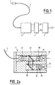
- FIG. 1 the pyrometer of the invention is illustrated diagrammatically in FIG. 1. It comprises an optical probe or sensor 1 placed facing a hot body, or in a gaseous medium, the temperature of which is to be measured and which is connected to a block optical 2 by means of a single optical fiber 3.
- a detection circuit placed at the output of the optical unit, or preferably integrated into this unit, allows conversion of the optical signals which it delivers into electrical signals usable by a set treatment 5 (after possibly conversion and adaptation by a conversion circuit 4) which then generates the value of the desired temperature.
- the configuration of the pyrometer presented is bichromatic, that is to say that the thermal radiation emitted by the surface of the hot body or the gas (the measurement probe then comprising a coating acting as a black micro-body) is measured on two spectral bands. separate. It is thus possible to limit the causes of errors corresponding to the losses in transmission and coupling of the radiation (curvatures, connectors, soiling) which directly affect the measurement in the case of a monochromatic analysis.
- a bichromatic structure requires to separate the radiation leaving the fiber into two parts. This is the object of the optical unit 2, the material structure of which is now described more precisely with reference to FIG. 2a.
- This optical unit 2 comprises, at the input, input collimation means 20 intended to transmit the radiation coming from the fiber 3 in parallel to means for separating this beam into two parts constituted by a dichroic plate 22 which also plays a filter role. high pass in transmission and low pass in reflection. The beams leaving this plate are then directed, directly or through a mirror 28, to spectral selection means (red and blue spectra) comprising interference filters 30, 32. Output focusing means 24, 26 placed at the output of these filters make it possible to concentrate the separated radiations on quantum detectors 33, 34, preferably with Gallium Indium Arsenide (In Ga As). The optical unit thus produced is particularly compact and has high performance.
- the signal levels available at the input of quantum detectors are higher than the signal levels which could be collected at the output of a separator cube and on the other hand the dichroic plate is not sensitive to polarization and does not introduce aberrations in the event of possible poor convergence of the radiation.
- the gain on each of the light fluxes leaving the blade, compared to a device with a separating cube, is 100%. It is thus possible either to use a fiber of smaller diameter for measuring the same temperature, or to extend the temperature range measured in particular towards low temperatures. It can be noted that in the case of broad spectral band measurements (300 to 400 nanometers), the interference filters 30, 32 can advantageously be omitted. It may also be noted that the use of achromatic optical doublets at the level of the focusing means also makes it possible to obtain an optimum spatial resolution allowing the use of detectors with a small surface.
- Figure 2b shows a second embodiment of the optical unit.
- the measurement can be carried out directly from the optical unit 2 by providing the latter with means allowing pyrometric aiming.
- These means comprise input focusing means 18 which capture the radiation and focus it at the focal point of the input collimating means 20, the light flux then going, as before, towards the separation means 22 and leading to the detectors 33 , 34.
- the electric currents delivered by the photovoltaic detectors are transformed into voltage and standardized in the current-voltage conversion circuit 4 which for reasons of improvement of the signal / noise ratio can advantageously be integrated into the optical unit.
- Vr red voltage
- Vb blue voltage
- the processing of the signals Vr and Vb on the basis of which the temperature T to be measured is determined is carried out in the processing circuit 5 of which various exemplary embodiments are shown in FIGS. 3 to 5.
- this circuit comprises a simplified architecture, both analog and digital, particularly suited to low measurement rates (of the order of 1000 measurements per second).
- this processing circuit comprises an entirely digital architecture organized around a digital microprocessor calculation unit 50 which receives the voltages Vr and Vb coming from the detectors and digitized by analog-digital converters 52, 54 and which, after calculation, delivers a digital value equal to the ratio of Vr / Vb for storage means 56 from which the measured temperature T is directly extracted, as before.
- a synchronization module 58 connected to the calculation unit 50 initiates the measurement process under the control of management software stored in a read-only memory 60 advantageously programmable and erasable (EPROM).
- EPROM programmable and erasable
- a display module 62 makes it possible to display the temperature T but also that of the ratio Vr / Vb.
- the converters In order to allow very fast measurement rates (up to 110,000 measurements per second), the converters have a resolution of 16 bits and include conversion times of the order of a microsecond.
- the ratio Vr / Vb is calculated in real time by the digital calculation unit 50 and is used as a pointer to extract the value of the temperature from the storage means which comprises, as previously, a table of values (conversion table) giving the temperature T for each Vr / Vb ratio.
- T A / (log (Vr / Vb) + B)
- Vr and Vb being the two color voltages (red and blue) delivered by the detectors and A and B two constants determined by a prior calibration.
- the signals Vr and Vb evolve in very large proportions whereas the ratio Vr / Vb remains on the contrary included in a fairly small range which it is easy to cover entirely with a conversion table of reasonable size.
- taking all the values of the ratio Vr / Vb between 0.3 and 2.6 in steps of 10-3 ⁇ we obtain a table having as input variable the ratio Vr / Vb and as output variable the temperature T and can be stored in a memory of 2048 words.
- the temperature measurement process is then summarized by simply calculating the ratio of the color voltages Vr / Vb and pointing in a memory containing this conversion table of the value of the corresponding temperature. Obviously, this original solution can also be used for lower rates as shown in the embodiment of FIG. 3.
- the calculation of the ratio Vr / Vb is carried out at the level of the calculation unit 50 which advantageously comprises a circuit specialized in the processing of digital signals such as a signal processor (Digital Signal Processor) for example, which makes it possible to carry out operations on 48 or even 56 bits.
- a signal processor Digital Signal Processor
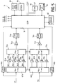
- FIG. 5 shows a preferred embodiment of the processing circuit 5.
- the signals Vr and Vb coming from the two measurement channels and delivered by the detector circuits 33, 34 each constitute input signals for, on the one hand, an analog converter -fast digital 60a; 60b and on the other hand a one-channel multiplexer circuit to at least two channels (advantageously four channels) 62a; 62b, each of the outputs of which is connected to an amplification circuit 64a, 66a, 68a, 70a; 64b, 66b, 68b, 70b, each circuit having an amplification factor separate (gain), preferably chosen in ratios 1, 4, 16, and 64.
- gain preferably chosen in ratios 1, 4, 16, and 64.
- the signals delivered by these amplification circuits are directed to a demultiplexer circuit of at least two channels (advantageously four channels) to a channel 72a, 74b the output of which is connected to a level adapter 74a; 74b which supplies an input voltage for an analog-digital converter 76a; 76b.
- the outputs of the two converters are connected to a digital calculation unit, a signal processor 78, which manages and controls all the circuits of the processing circuit and generates the digital value T of the measured temperature.
- a digital-analog converter 80 optionally makes it possible to have this temperature in analog form.
- the processing circuit 5 also comprises connected to the processor 78 a synchronization module 82, a set of data input and output (in the form of a keyboard and a display) 84, a read only memory 86 and a memory fast fast (flash type) 88.
- the measurement process is triggered by the synchronization module 82 under the control of a management software stored in the read-only memory 86 which is advantageously programmable and erasable (EPROM).
- EPROM programmable and erasable
- This process begins with a rapid but coarse conversion, for example on a simple 6-bit conversion, carried out by the fast converters 60a, 60b, in order to estimate the orders of magnitude of the color voltages Vr and Vb.
- the processor 78 determines the most suitable gain (1, 4, 16 or 64) on each of the two measurement channels (this determination is carried out in real time for each measurement point), thus allowing a reduction of signal dynamics.
- the adaptation stage 74a, 74b makes it possible to calibrate the signals delivered by the amplification circuits selected to benefit from the totality of the resolution of the analog-digital converter 76a, 76b which performs the conversion preferably on at least 12 bits.
- the digitized Vr and Vb values are used to calculate the Vr / Vb ratio executed by the arithmetic and logic processing unit of processor 78.
- FIG. 6 An exemplary embodiment of the gain amplification circuits 4, 16 or 64, the unit gain amplification circuit being conventionally produced by a simple operational amplifier mounted as a voltage follower, is illustrated in FIG. 6.
- the stage d he input consists of an operational amplifier with field effect transistors (TEC) 90 making it possible to obtain a very low offset current and varying little with the temperature.
- TEC field effect transistors
- the weakness of the bandwidth and the maximum rate of change of its output voltage (slew-rate) of this TEC amplifier is compensated by the presence at its output of a second operational amplifier with bipolar transistors 92 which, on the contrary, has a bandwidth and a slew-rate very high.
- the signal Ve from the multiplexer circuit 62a; 62b is directed towards the non-inverting input of the first amplifier 90, its inverting input being connected to the midpoint of an adjustable potentiometer ⁇ R whose two ends are respectively connected to one end of a first resistor R1 whose other end is connected to the output of the second amplifier 92 and to one end of a second resistor R2, the other end of which is connected to a positive reference potential.
- the output of the first amplifier constitutes the inverting input of the second amplifier whose non-inverting input is looped over the output of this second amplifier by a third resistor R3 and connected to a negative reference potential through a fourth resistor R4 .
- the synchronization module 58, 82 responsible for triggering the measurement process by activating the corresponding interruption of the processor 50, 78 is shown in FIG. 7.
- This module comprises a four-channel multiplexer circuit to a channel 94 which receives respectively on each of its four inputs: an external signal, the output signals of two clock circuits 96, 98 of frequency 10 and 10,000 Hz and the output signal of a comparator 99 receiving on the one hand the signal Vb and on the other hand a predetermined threshold voltage.
- the selection of one or the other of these signals is carried out from the signal processor 78 which thus generates four distinct synchronization modes: a slow mode for the calibration in which the constants A and B and the values of Vr and Vb are entered manually on the keyboard (in this mode, the measurement frequency is advantageously a few Hz, for example 10 Hz and the bandwidth on each channel is then limited) and three fast modes which differ in the principle of triggering the measurement .
- a slow mode for the calibration in which the constants A and B and the values of Vr and Vb are entered manually on the keyboard (in this mode, the measurement frequency is advantageously a few Hz, for example 10 Hz and the bandwidth on each channel is then limited) and three fast modes which differ in the principle of triggering the measurement .
- the temperature calculation is triggered by an external logic signal, this calculation can then be executed up to 110,000 times per second.
- an internal synchronization mode the calculation is triggered by the signal Vb as soon as it exceeds the predetermined voltage threshold.
- the different frequencies mentioned above are given for information only and it is possible by modifying them to adapt the pyrometer according to the invention to a very large number of situations.
- the pyrometer is capable of characterizing phenomena with natural periodicities (turbine blades for example) as processes presenting any a priori variations.
- the processor waits, in a step 102, for an interrupt signal which can be generated by the synchronization module 82 (temperature calculation function) or by the circuit management of display and keyboard 84 (calibration function).
- the processor reads the voltage values Vr, Vb delivered by the fast converters 60a, 60b then, in step 106, it selects the gain best suited to the conversion analog-digital which it launches in a step 108. At the same time, in a step 110, it proceeds to the calculation of the ratio Vr / Vb (on the values resulting from the previous conversion). In the next step 112, it reads from the conversion table the value of the corresponding temperature and, in step 114, this value T is sent to a digital output or addressed to the converter 80 which delivers the analog equivalent t on its way out.
- step 116 the values Vr and Vb are read by the processor and saved for the calculation to come and the gain is reset to 1 during the next step 118.
- the process either returns to the initial standby state (step 102) or addresses the values of T and Vr / Vb to the display management circuit 84.
- the interruption results from the keyboard management circuit 84, an analysis of the message entered is carried out and the corresponding action is then executed. It can be a change of mode or a calibration with modification of parameters A and B. This action finished, the processor returns to its initial state waiting for a new interruption from the keyboard or the synchronization module.
- Figures 9 and 10 illustrate two possible architectures for the measurement probe 1.
- these probes use a conventional optical fiber 120, without any focusing device, which is then placed opposite the surface whose temperature is to be measured. , this surface being able to be brought to temperature simply by the displacement of a gas coming to touch it.
- a fiber is for example a multimode fiber with an index jump in silica / silica (core / cladding).
- the transparent fiber is advantageously covered with a thin layer 122 of an opaque material which provides it with sufficient thermal and mechanical protection but specific to each application (deposition of a refractory material by plasma spraying for example).
- the fiber probe is connected to the transmission fiber 3 Dar a connection not shown.
- the probe is constituted by a cylindrical sapphire bar 130 whose face of exposure to radiation can be produced in the form of a hemispherical cap 132 whose radius varies in a determined manner depending on the intended application.
- a simply perpendicular face can also be envisaged.
- the exit face of the sapphire opposite the fiber is advantageously produced in the form of a spherical cap 134 which allows focusing of practically almost all of the flux to be conveyed in the fiber 3 (maximization of the optical coupling with the fiber) .
- This solution which avoids the use of a lens whose positioning is always delicate is particularly reliable given the small number of parts involved. It also has the advantage of low cost and that of retaining the intrinsic qualities of the bar. sapphire.
- the external surface of the bar has thermal and mechanical protection 136.
- the hemispherical cap 132 is covered with different layers having the object of creating at the free end of the sapphire a coating conferring an emission black body type thermal.
- These layers the total thickness of which does not exceed 10 to 15 ⁇ m (in particular for obtaining a good temporal response) optimize on the one hand the emission and the heat transfer and on the other hand the thermomechanical and chemical behavior of the probe depending on its environment (reducing or oxidizing medium).
- Each layer has a specific function; a first layer 138 highly emissive, and a second layer 142 opaque and highly conductive. Two layers are sufficient, however an intermediate layer 140 can be added to optimize the diffusion of heat and thus homogenize the temperature.
- This pyrometer can therefore allow the knowledge of very complete experimental data on phenomena still little studied because it is beyond the scope of conventional instrumentation.
Landscapes
- Physics & Mathematics (AREA)
- General Physics & Mathematics (AREA)
- Spectroscopy & Molecular Physics (AREA)
- Radiation Pyrometers (AREA)
Applications Claiming Priority (2)
| Application Number | Priority Date | Filing Date | Title |
|---|---|---|---|
| FR9412588A FR2726081B1 (fr) | 1994-10-21 | 1994-10-21 | Pyrometre bichromatique rapide a fibre optique |
| FR9412588 | 1994-10-21 |
Publications (3)
| Publication Number | Publication Date |
|---|---|
| EP0708317A1 true EP0708317A1 (de) | 1996-04-24 |
| EP0708317B1 EP0708317B1 (de) | 2002-01-30 |
| EP0708317B2 EP0708317B2 (de) | 2010-06-09 |
Family
ID=9468078
Family Applications (1)
| Application Number | Title | Priority Date | Filing Date |
|---|---|---|---|
| EP95402286A Expired - Lifetime EP0708317B2 (de) | 1994-10-21 | 1995-10-13 | Schnelles bichromatisches fiberoptisches Pyrometer |
Country Status (5)
| Country | Link |
|---|---|
| US (1) | US5755510A (de) |
| EP (1) | EP0708317B2 (de) |
| DE (1) | DE69525212T3 (de) |
| ES (1) | ES2171514T5 (de) |
| FR (1) | FR2726081B1 (de) |
Cited By (2)
| Publication number | Priority date | Publication date | Assignee | Title |
|---|---|---|---|---|
| EP0930486A1 (de) * | 1998-01-20 | 1999-07-21 | Auxitrol SA | Messfühler zum Messen von Temperatur und/oder Konzentration |
| FR2773878A1 (fr) * | 1998-01-20 | 1999-07-23 | Auxitrol Sa | Capteur de mesure d'une temperature |
Families Citing this family (18)
| Publication number | Priority date | Publication date | Assignee | Title |
|---|---|---|---|---|
| US6373562B1 (en) * | 1998-10-09 | 2002-04-16 | Kim A. Marsh | Fiberoptic cable tester |
| US6151446A (en) * | 1999-07-06 | 2000-11-21 | Applied Materials, Inc. | Apparatus and method for thermally processing substrates including a processor using multiple detection signals |
| US7690840B2 (en) * | 1999-12-22 | 2010-04-06 | Siemens Energy, Inc. | Method and apparatus for measuring on-line failure of turbine thermal barrier coatings |
| GB0000954D0 (en) * | 2000-01-18 | 2000-03-08 | Renishaw Plc | Spectroscopic probe |
| US6698920B1 (en) * | 2000-05-08 | 2004-03-02 | General Electric Company | Temperature measuring system and optical switch used therein |
| US6786634B2 (en) * | 2001-10-10 | 2004-09-07 | Noritake Co., Limited | Temperature measuring method and apparatus |
| US20040179575A1 (en) * | 2003-01-23 | 2004-09-16 | Markham James R. | Instrument for temperature and condition monitoring of advanced turbine blades |
| US7075629B2 (en) * | 2003-05-12 | 2006-07-11 | Honeywell International Inc. | High temperature pyrometer |
| US7826954B2 (en) * | 2004-06-25 | 2010-11-02 | Honda Motor Co., Ltd. | System for monitoring sensor outputs of a gas turbine engine |
| US7432505B2 (en) * | 2006-05-04 | 2008-10-07 | Siemens Power Generation, Inc. | Infrared-based method and apparatus for online detection of cracks in steam turbine components |
| US7633066B2 (en) * | 2006-05-22 | 2009-12-15 | General Electric Company | Multiwavelength pyrometry systems |
| US8790006B2 (en) * | 2009-11-30 | 2014-07-29 | General Electric Company | Multiwavelength thermometer |
| DE102011016102A1 (de) * | 2011-01-07 | 2012-07-12 | Heraeus Noblelight Gmbh | Verfahren zur Bestimmung der Infrarot-Abstrahlung |
| US20120230366A1 (en) * | 2011-03-10 | 2012-09-13 | Yaosheng Chen | Optical Digital Thermometer |
| DE102012011924B3 (de) * | 2012-06-15 | 2013-11-21 | Keller Hcw Gmbh | Verfahren und Vorrichtung zur berührungslosen Temperaturmessung an bewegten, langgestreckten Messobjekten |
| US11215508B2 (en) * | 2019-02-01 | 2022-01-04 | Solar Turbines Incorporated | Temperature measuring system |
| CN110455417B (zh) * | 2019-08-21 | 2020-08-04 | 北京环境特性研究所 | 针对红外光学系统杂散辐射的定量测量误差校正方法 |
| US12487124B2 (en) * | 2022-01-31 | 2025-12-02 | General Electric Company | Systems and methods for measuring temperature |
Citations (7)
| Publication number | Priority date | Publication date | Assignee | Title |
|---|---|---|---|---|
| GB2068109A (en) * | 1980-01-21 | 1981-08-05 | Europ Electronic Syst Ltd | Monitoring strip temperature |
| GB2160971A (en) * | 1984-06-26 | 1986-01-02 | Land Infrared Ltd | Temperature monitoring |
| EP0216458A1 (de) | 1985-08-08 | 1987-04-01 | Rosemount Inc. | Pyrometer zur Temperaturmessung |
| WO1991003715A1 (en) | 1989-09-04 | 1991-03-21 | Rolf Hernberg | Method and apparatus for measuring of surface temperature of fuel particles in a fluidized bed |
| EP0425229A1 (de) * | 1989-10-25 | 1991-05-02 | Tacan Corporation | Hochtemperatursensor |
| DE4028408A1 (de) * | 1990-09-07 | 1992-03-19 | Tzn Forschung & Entwicklung | Verfahren und vorrichtung zur beruehrungslosen temperaturmessung |
| GB2257508A (en) * | 1991-06-28 | 1993-01-13 | Ferodo Ltd | Apparatus for temperature variation detection |
Family Cites Families (10)
| Publication number | Priority date | Publication date | Assignee | Title |
|---|---|---|---|---|
| US3922550A (en) * | 1973-12-28 | 1975-11-25 | Raytheon Co | Radiometric system |
| DE2405651B2 (de) * | 1974-02-04 | 1980-08-14 | Mannesmann Ag, 4000 Duesseldorf | Pyrometer |
| US4075493A (en) † | 1976-12-16 | 1978-02-21 | Ronald Alves | Optical temperature measurement technique utilizing phosphors |
| GB1602160A (en) * | 1978-04-26 | 1981-11-11 | Negretti & Zambra Aviat Ltd | Pyrometers |
| DE3202089C2 (de) † | 1982-01-23 | 1985-01-17 | Fa. Carl Zeiss, 7920 Heidenheim | Faseroptischer Temperatursensor |
| US4764025A (en) * | 1985-08-08 | 1988-08-16 | Rosemount Inc. | Turbine blade temperature detecting pyrometer |
| US5188458A (en) * | 1988-04-27 | 1993-02-23 | A G Processing Technologies, Inc. | Pyrometer apparatus and method |
| US5021980A (en) † | 1989-02-21 | 1991-06-04 | Lsi Logic Corporation | Remote measurement of temperature |
| US5154512A (en) * | 1990-04-10 | 1992-10-13 | Luxtron Corporation | Non-contact techniques for measuring temperature or radiation-heated objects |
| FR2703455B1 (fr) * | 1993-04-01 | 1995-05-12 | Europ Gas Turbines Sa | Pyromètre bichromatique. |
-
1994
- 1994-10-21 FR FR9412588A patent/FR2726081B1/fr not_active Expired - Fee Related
-
1995
- 1995-10-13 EP EP95402286A patent/EP0708317B2/de not_active Expired - Lifetime
- 1995-10-13 DE DE69525212T patent/DE69525212T3/de not_active Expired - Lifetime
- 1995-10-13 ES ES95402286T patent/ES2171514T5/es not_active Expired - Lifetime
- 1995-10-20 US US08/546,454 patent/US5755510A/en not_active Expired - Lifetime
Patent Citations (7)
| Publication number | Priority date | Publication date | Assignee | Title |
|---|---|---|---|---|
| GB2068109A (en) * | 1980-01-21 | 1981-08-05 | Europ Electronic Syst Ltd | Monitoring strip temperature |
| GB2160971A (en) * | 1984-06-26 | 1986-01-02 | Land Infrared Ltd | Temperature monitoring |
| EP0216458A1 (de) | 1985-08-08 | 1987-04-01 | Rosemount Inc. | Pyrometer zur Temperaturmessung |
| WO1991003715A1 (en) | 1989-09-04 | 1991-03-21 | Rolf Hernberg | Method and apparatus for measuring of surface temperature of fuel particles in a fluidized bed |
| EP0425229A1 (de) * | 1989-10-25 | 1991-05-02 | Tacan Corporation | Hochtemperatursensor |
| DE4028408A1 (de) * | 1990-09-07 | 1992-03-19 | Tzn Forschung & Entwicklung | Verfahren und vorrichtung zur beruehrungslosen temperaturmessung |
| GB2257508A (en) * | 1991-06-28 | 1993-01-13 | Ferodo Ltd | Apparatus for temperature variation detection |
Non-Patent Citations (2)
| Title |
|---|
| S. WALTER: "New Instrumentation for Advanced Turbine Research", MECHANICAL ENGINEERING, vol. 105, no. 2, pages 43 - 51, XP000615054 * |
| SAM WALTERS: "New instrumentation for advanced turbine research", MECHANICAL ENGINEERING, vol. 105, 1983, XP000615054 |
Cited By (4)
| Publication number | Priority date | Publication date | Assignee | Title |
|---|---|---|---|---|
| EP0930486A1 (de) * | 1998-01-20 | 1999-07-21 | Auxitrol SA | Messfühler zum Messen von Temperatur und/oder Konzentration |
| FR2773879A1 (fr) * | 1998-01-20 | 1999-07-23 | Auxitrol Sa | Capteur de mesure d'une temperature |
| FR2773878A1 (fr) * | 1998-01-20 | 1999-07-23 | Auxitrol Sa | Capteur de mesure d'une temperature |
| US6341890B1 (en) | 1998-01-20 | 2002-01-29 | Auxitrol S.A. | Sensor for measuring temperature and/or concentration |
Also Published As
| Publication number | Publication date |
|---|---|
| EP0708317B2 (de) | 2010-06-09 |
| ES2171514T5 (es) | 2010-10-28 |
| EP0708317B1 (de) | 2002-01-30 |
| US5755510A (en) | 1998-05-26 |
| FR2726081A1 (fr) | 1996-04-26 |
| DE69525212T3 (de) | 2010-12-30 |
| FR2726081B1 (fr) | 1997-01-10 |
| ES2171514T3 (es) | 2002-09-16 |
| DE69525212D1 (de) | 2002-03-14 |
| DE69525212T2 (de) | 2002-10-24 |
Similar Documents
| Publication | Publication Date | Title |
|---|---|---|
| EP0708317B1 (de) | Schnelles bichromatisches fiberoptisches Pyrometer | |
| Turner et al. | Silicon nitride micromesh bolometer array for submillimeter astrophysics | |
| Pan et al. | Mid-infrared Nb4N3-based superconducting nanowire single photon detectors for wavelengths up to 10 µm | |
| Wollman et al. | SNSPD-based detector system for NASA’s Deep Space Optical Communications project | |
| EP0618432A2 (de) | Zwei-Farben Pyrometer | |
| FR2738693A1 (fr) | Systeme de traitement d'impulsions provenant de l'interaction d'une particule gamma avec un detecteur de rayonnement cdte | |
| EP0187087B1 (de) | Photonenabtasteinrichtung und diese Einrichtung benutzendes Transientenanalysesystem | |
| Shiokawa et al. | Three-channel imaging Fabry–Perot interferometer for measurement of mid-latitude airglow | |
| Kaplan et al. | Testing the radiometric accuracy of Fourier transform infrared transmittance measurements | |
| Hawkins et al. | Cooled infrared filters and dichroics for the Sea and Land Surface Temperature Radiometer | |
| Nakajima et al. | Observations of thermospheric wind velocities and temperatures by the use of a Fabry–Perot Doppler imaging system at Syowa Station, Antarctica | |
| CA2881524C (fr) | Dispositif d'amplification analogique destine notamment a un anemometre laser | |
| EP0201415B1 (de) | Logarithmische Wandler und ihre Anwendung zur übertragenen Lichtmessung | |
| FR2847978A1 (fr) | Spectrometre compact a composant optique monolithique | |
| Taylor et al. | Infrared radiometer for the Pioneer Venus orbiter. 1: Instrument description | |
| Boboridis et al. | A High‐Speed Four‐Channel Infrared Pyrometer | |
| EP0345121A1 (de) | Optisches Pyrometer mit mindestens einer optischen Faser | |
| WO2006037879A1 (fr) | Detection des emissions de fluorescence induite par un laser | |
| EP3685226A1 (de) | Infrarot-bildgeber | |
| EP4094069A1 (de) | System zur erfassung von punktwerten zur bildung eines bildes mit terahertzstrahlung | |
| FR3084158A1 (fr) | Methode et dispositif de caracterisation de filtres optiques | |
| EP3968066A1 (de) | Wellenleiter, der eine optische multimode-faser umfasst und die geführten moden räumlich konzentrieren kann | |
| FR2810108A1 (fr) | Ellipsometre spectroscopique a faible bruit | |
| WO2021152244A1 (fr) | Système de mesure d'une pluralité de paramètres physiques en un point de mesure par une fibre optique multimode | |
| Barth | High-transmission 20-channel polychromator for observing non-Maxwellian electron velocity distributions in plasmas by Thomson scattering |
Legal Events
| Date | Code | Title | Description |
|---|---|---|---|
| PUAI | Public reference made under article 153(3) epc to a published international application that has entered the european phase |
Free format text: ORIGINAL CODE: 0009012 |
|
| AK | Designated contracting states |
Kind code of ref document: A1 Designated state(s): CH DE ES GB LI |
|
| 17P | Request for examination filed |
Effective date: 19960905 |
|
| RAP1 | Party data changed (applicant data changed or rights of an application transferred) |
Owner name: SOCIETE NATIONALE D'ETUDE ET DE CONSTRUCTION DE MO |
|
| 17Q | First examination report despatched |
Effective date: 19981001 |
|
| GRAG | Despatch of communication of intention to grant |
Free format text: ORIGINAL CODE: EPIDOS AGRA |
|
| GRAG | Despatch of communication of intention to grant |
Free format text: ORIGINAL CODE: EPIDOS AGRA |
|
| GRAH | Despatch of communication of intention to grant a patent |
Free format text: ORIGINAL CODE: EPIDOS IGRA |
|
| GRAH | Despatch of communication of intention to grant a patent |
Free format text: ORIGINAL CODE: EPIDOS IGRA |
|
| GRAA | (expected) grant |
Free format text: ORIGINAL CODE: 0009210 |
|
| REG | Reference to a national code |
Ref country code: GB Ref legal event code: IF02 |
|
| AK | Designated contracting states |
Kind code of ref document: B1 Designated state(s): CH DE ES GB LI |
|
| REG | Reference to a national code |
Ref country code: CH Ref legal event code: EP |
|
| REF | Corresponds to: |
Ref document number: 69525212 Country of ref document: DE Date of ref document: 20020314 |
|
| REG | Reference to a national code |
Ref country code: CH Ref legal event code: NV Representative=s name: MICHELI & CIE INGENIEURS-CONSEILS |
|
| GBT | Gb: translation of ep patent filed (gb section 77(6)(a)/1977) |
Effective date: 20020501 |
|
| REG | Reference to a national code |
Ref country code: ES Ref legal event code: FG2A Ref document number: 2171514 Country of ref document: ES Kind code of ref document: T3 |
|
| PLBQ | Unpublished change to opponent data |
Free format text: ORIGINAL CODE: EPIDOS OPPO |
|
| PLBI | Opposition filed |
Free format text: ORIGINAL CODE: 0009260 |
|
| PLBF | Reply of patent proprietor to notice(s) of opposition |
Free format text: ORIGINAL CODE: EPIDOS OBSO |
|
| 26 | Opposition filed |
Opponent name: DIAS ANGEWANDTE SENSORIK GMBH Effective date: 20021023 |
|
| PLBF | Reply of patent proprietor to notice(s) of opposition |
Free format text: ORIGINAL CODE: EPIDOS OBSO |
|
| PLBF | Reply of patent proprietor to notice(s) of opposition |
Free format text: ORIGINAL CODE: EPIDOS OBSO |
|
| PLCK | Communication despatched that opposition was rejected |
Free format text: ORIGINAL CODE: EPIDOSNREJ1 |
|
| APBP | Date of receipt of notice of appeal recorded |
Free format text: ORIGINAL CODE: EPIDOSNNOA2O |
|
| APAH | Appeal reference modified |
Free format text: ORIGINAL CODE: EPIDOSCREFNO |
|
| APBQ | Date of receipt of statement of grounds of appeal recorded |
Free format text: ORIGINAL CODE: EPIDOSNNOA3O |
|
| APBU | Appeal procedure closed |
Free format text: ORIGINAL CODE: EPIDOSNNOA9O |
|
| PLAY | Examination report in opposition despatched + time limit |
Free format text: ORIGINAL CODE: EPIDOSNORE2 |
|
| PLAY | Examination report in opposition despatched + time limit |
Free format text: ORIGINAL CODE: EPIDOSNORE2 |
|
| PLBC | Reply to examination report in opposition received |
Free format text: ORIGINAL CODE: EPIDOSNORE3 |
|
| PUAH | Patent maintained in amended form |
Free format text: ORIGINAL CODE: 0009272 |
|
| STAA | Information on the status of an ep patent application or granted ep patent |
Free format text: STATUS: PATENT MAINTAINED AS AMENDED |
|
| 27A | Patent maintained in amended form |
Effective date: 20100609 |
|
| AK | Designated contracting states |
Kind code of ref document: B2 Designated state(s): CH DE ES GB LI |
|
| REG | Reference to a national code |
Ref country code: CH Ref legal event code: AEN Free format text: BREVET MAINTENU DANS UNE FORME MODIFIEE |
|
| REG | Reference to a national code |
Ref country code: ES Ref legal event code: DC2A Date of ref document: 20100908 Kind code of ref document: T5 |
|
| PGFP | Annual fee paid to national office [announced via postgrant information from national office to epo] |
Ref country code: DE Payment date: 20100930 Year of fee payment: 16 |
|
| PGFP | Annual fee paid to national office [announced via postgrant information from national office to epo] |
Ref country code: CH Payment date: 20110923 Year of fee payment: 17 |
|
| PGFP | Annual fee paid to national office [announced via postgrant information from national office to epo] |
Ref country code: GB Payment date: 20110926 Year of fee payment: 17 |
|
| PGFP | Annual fee paid to national office [announced via postgrant information from national office to epo] |
Ref country code: ES Payment date: 20111006 Year of fee payment: 17 |
|
| REG | Reference to a national code |
Ref country code: GB Ref legal event code: 732E Free format text: REGISTERED BETWEEN 20120517 AND 20120523 |
|
| REG | Reference to a national code |
Ref country code: ES Ref legal event code: PC2A Owner name: SNECMA Effective date: 20120816 |
|
| REG | Reference to a national code |
Ref country code: DE Ref legal event code: R082 Ref document number: 69525212 Country of ref document: DE Representative=s name: MAIWALD PATENTANWALTSGESELLSCHAFT MBH, DE |
|
| REG | Reference to a national code |
Ref country code: DE Ref legal event code: R082 Ref document number: 69525212 Country of ref document: DE Representative=s name: MAIWALD PATENTANWALTSGESELLSCHAFT MBH, DE Effective date: 20121005 Ref country code: DE Ref legal event code: R081 Ref document number: 69525212 Country of ref document: DE Owner name: SNECMA, FR Free format text: FORMER OWNER: SOCIETE NATIONALE D'ETUDE ET DE CONSTRUCTION DE MOTEURS D'AVIATION (S.N.E.C.M.A.), PARIS, FR Effective date: 20121005 |
|
| REG | Reference to a national code |
Ref country code: CH Ref legal event code: PL |
|
| GBPC | Gb: european patent ceased through non-payment of renewal fee |
Effective date: 20121013 |
|
| PG25 | Lapsed in a contracting state [announced via postgrant information from national office to epo] |
Ref country code: GB Free format text: LAPSE BECAUSE OF NON-PAYMENT OF DUE FEES Effective date: 20121013 Ref country code: DE Free format text: LAPSE BECAUSE OF NON-PAYMENT OF DUE FEES Effective date: 20130501 Ref country code: LI Free format text: LAPSE BECAUSE OF NON-PAYMENT OF DUE FEES Effective date: 20121031 Ref country code: CH Free format text: LAPSE BECAUSE OF NON-PAYMENT OF DUE FEES Effective date: 20121031 |
|
| REG | Reference to a national code |
Ref country code: DE Ref legal event code: R119 Ref document number: 69525212 Country of ref document: DE Effective date: 20130501 |
|
| REG | Reference to a national code |
Ref country code: ES Ref legal event code: FD2A Effective date: 20140116 |
|
| PG25 | Lapsed in a contracting state [announced via postgrant information from national office to epo] |
Ref country code: ES Free format text: LAPSE BECAUSE OF NON-PAYMENT OF DUE FEES Effective date: 20121014 |