EP0706930A2 - Elektrische Servolenkung - Google Patents
Elektrische Servolenkung Download PDFInfo
- Publication number
- EP0706930A2 EP0706930A2 EP95116104A EP95116104A EP0706930A2 EP 0706930 A2 EP0706930 A2 EP 0706930A2 EP 95116104 A EP95116104 A EP 95116104A EP 95116104 A EP95116104 A EP 95116104A EP 0706930 A2 EP0706930 A2 EP 0706930A2
- Authority
- EP
- European Patent Office
- Prior art keywords
- motor
- state
- detected
- drive
- torque
- Prior art date
- Legal status (The legal status is an assumption and is not a legal conclusion. Google has not performed a legal analysis and makes no representation as to the accuracy of the status listed.)
- Granted
Links
Images


Classifications
-
- B—PERFORMING OPERATIONS; TRANSPORTING
- B62—LAND VEHICLES FOR TRAVELLING OTHERWISE THAN ON RAILS
- B62D—MOTOR VEHICLES; TRAILERS
- B62D5/00—Power-assisted or power-driven steering
- B62D5/04—Power-assisted or power-driven steering electrical, e.g. using an electric servo-motor connected to, or forming part of, the steering gear
- B62D5/0457—Power-assisted or power-driven steering electrical, e.g. using an electric servo-motor connected to, or forming part of, the steering gear characterised by control features of the drive means as such
- B62D5/046—Controlling the motor
- B62D5/0463—Controlling the motor calculating assisting torque from the motor based on driver input
-
- B—PERFORMING OPERATIONS; TRANSPORTING
- B62—LAND VEHICLES FOR TRAVELLING OTHERWISE THAN ON RAILS
- B62D—MOTOR VEHICLES; TRAILERS
- B62D5/00—Power-assisted or power-driven steering
- B62D5/04—Power-assisted or power-driven steering electrical, e.g. using an electric servo-motor connected to, or forming part of, the steering gear
- B62D5/0457—Power-assisted or power-driven steering electrical, e.g. using an electric servo-motor connected to, or forming part of, the steering gear characterised by control features of the drive means as such
- B62D5/0481—Power-assisted or power-driven steering electrical, e.g. using an electric servo-motor connected to, or forming part of, the steering gear characterised by control features of the drive means as such monitoring the steering system, e.g. failures
- B62D5/0493—Power-assisted or power-driven steering electrical, e.g. using an electric servo-motor connected to, or forming part of, the steering gear characterised by control features of the drive means as such monitoring the steering system, e.g. failures detecting processor errors, e.g. plausibility of steering direction
Definitions
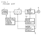
- FIG. 1 is a block diagram schematically showing the configuration of a prior art electric power steering apparatus.
- a CPU 2 determines a motor current target value of a steering force assisting motor 4 on the basis of a torque detected by a torque sensor 1, and controls a motor drive circuit 3 with using the motor current target value as a target value of an automatic control, thereby driving the motor 4.
- the driving current of the motor 4 which is detected by a motor current detecting circuit 5 is supplied to the CPU 2 as the feedback value of the automatic control.
- the torque detected by the torque sensor 1 is supplied also to a direction inhibition region judging circuit 8.
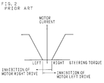
- a motor drive inhibition region where, when the detected torque is greater than a predetermined value in either of the right and left directions, the motor 4 is inhibited from being driven in the direction opposite to the detected torque is previously set in the direction inhibition region judging circuit 8.
- a motor drive inhibiting circuit 14 inhibits the motor 4 from being driven in the direction opposite to the detected torque, so that, when the CPU 2 runs away, the steering wheel is prevented from being subjected to self-rotation or reverse assist (assist of the steering force in the opposite direction).
- the drive inhibition holding means holds the motor drive inhibition state where the motor is inhibited from being driven in the direction opposite to the detected torque, until the non-drive detecting means detects that the motor current target value is zero. Even when a CPU runs away and the motor current target value becomes excessive, therefore, self-rotation and reverse assist of a steering wheel caused by the flow of an excess motor current are prevented from occurring. Furthermore, even when the CPU runs away and the assist and the assist inhibition are repeated, the steering is prevented from becoming unstable.
- the motor when a first state where the detected torque is outside the dead zone (the zone where the motor current target value is to be zero) and the direction in which the motor is to be driven in accordance with the current target value is opposite to that of the detected torque is detected, the motor is inhibited from being driven.
- the motor when a third state where the detected torque is outside the dead zone, the direction in which the motor is to be driven in accordance with the current target value is opposite to that of the detected torque is detected and the direction in which the motor is to be driven in accordance with the current target value is opposite to the change direction of the detected torque is detected, the motor is inhibited from being driven.
- the motor driving current is greater than a predetermined value, and the direction in which the motor is to be driven by the motor driving current is opposite to the change direction of the detected torque is detected, the motor is inhibited from being driven. In this case, it is possible to perform the return control of the steering wheel.
- a detection timer starts a timer operation for a first predetermined time, and, when the first, second, third, or fourth state is not detected any longer, the timer operation is reset.
- the detection timer completes the timer operation for the first predetermined time but the first, second, third, or fourth state is kept detected, the motor is inhibited from being driven. In this case, it is possible to monitor a runaway of the CPU without disturbing the differential control of the torque signal.
- an indication lamp is lit.
- the judgment whether the direction in which the motor is to be driven in accordance with the current target value is opposite to the change direction of the detected torque or not may be added to the factor in judging abnormality. In this case, it is possible to detect a runaway of the CPU in a short time, and a safety countermeasure against a runaway of the CPU can be taken sufficiently.
- the drive logic judging circuit 9 judges whether the detected torque is outside the dead zone or not and whether the direction in which the motor 4 is to be driven in accordance with the motor current target value is opposite to the change direction of the detected torque or not.
- the abnormal current judging circuit 6 judges whether the detected torque is inside the dead zone or not and whether the motor driving current is greater than a predetermined value or not.
- the judgment results of the circuits 9 and 6 are supplied to a drive abnormality detecting circuit 7.
- the predetermined value of the driving current of the motor 4 is set to be a value which is greater than the maximum value of the return current of the steering wheel and which does not cause the electric power steering apparatus to become unstable.
- a detection timer 12 and a definition timer 15 start the timer operations for predetermined times T1 and T2, respectively.
- a latch circuit 13 holds an abnormality detection signal from the drive abnormality detecting circuit 7. During a period when the latch circuit 13 holds the abnormality detection signal from the drive abnormality detecting circuit 7, a diagnosis lamp 19 is lit and the motor drive inhibiting circuit 14 stops the operation of the motor drive circuit 3.
- the motor non-drive detecting circuit 11 for detecting that the motor current target value is zero detects that the value is zero, the latch circuit 13 is cleared.
- a latch circuit 16 holds the abnormality detection signal from the drive abnormality detecting circuit 7.
- the diagnosis lamp 19 is lit and a relay drive inhibiting circuit 17 causes a fail safe relay 18 which connects the motor drive circuit 3 with a power source, to be turned off.
- the torque detected by the torque sensor 1 is supplied to the direction inhibition region judging circuit 8a.
- the direction inhibition region judging circuit 8a judges the direction and magnitude of the detected torque.
- a signal indicative of the direction of the detected torque is sent to the drive logic judging circuit 9.
- a signal indicative of the magnitudinous relationship with a predetermined value (inside the dead zone or outside the dead zone) in each of the right and left directions as shown in FIG. 4 is sent to the dead zone detecting circuit 10.
- the dead zone detecting circuit 10 supplies a notification signal which indicates whether the detected torque is inside or outside the dead zone, to the drive logic judging circuit 9 and the abnormal current judging circuit 6.
- the drive abnormality detecting circuit 7 activates the detection timer 12 and the definition timer 15, and, when the abnormality notification from the drive logic judging circuit 9 or the abnormal current judging circuit 6 is interrupted, resets the detection timer 12 and the definition timer 15.
- the latch circuit 13 When the detection timer 12 completes the timer operation for the predetermined time T1 while the abnormality notification from the drive logic judging circuit 9 or the abnormal current judging circuit 6 to the drive abnormality detecting circuit 7 is continued without interruption, the latch circuit 13 is caused to hold the abnormality notification from the drive logic judging circuit 9 or the abnormal current judging circuit 6. During a period when the latch circuit 13 holds the abnormality notification, the diagnosis lamp 19 is lit and the motor drive inhibiting circuit 14 is operated so that the motor 4 is inhibited from being driven. During this period, when the motor non-drive detecting circuit 11 detects that the motor current target value is zero, the latch circuit 13 is cleared and the operation of the motor drive inhibiting circuit 14 is stopped so that the inhibition of the drive of the motor 4 is canceled.
- the CPU 2 determines the assist current and the steering wheel return current on the basis of the torque signal, and performs the angular velocity difference control (differential control of the torque signal). Therefore, the state where, although the direction in which the motor 4 is to be driven in accordance with the motor current target value is opposite to the direction of the detected torque or the detected torque is inside the dead zone, the driving current of the motor 4 is large occurs instantaneously. This may result in that, even though the CPU 2 is normal (is not running away), a drive abnormality is detected. Consequently, the predetermined time T1 of the detection timer 12 must be set to be longer than a period when the drive abnormality detecting circuit 7 operates in a normal state.
- the predetermined time T1 of the detection timer 12 must be set to be within a period during which the safety can be ensured in the case of a runaway of the CPU 2. Consequently, the detection timer 12 must operate so that, when the CPU 2 is normal, a runaway of the CPU 2 is not erroneously detected and, when the CPU 2 runs away, the motor 4 is turned off thereby ensuring the safety.
- the apparatus is not configured so that the latch circuit 13 is not cleared unless the motor non-drive detecting circuit 11 once detects that the motor current target value is zero (non-driven), there arises a problem as discussed below.
- the CPU 2 runs away and the motor current target value becomes excessive, even when the detected torque is inside the dead zone, a large current flows through the motor 4 during the period when the detection timer 12 performs the timer operation for the predetermined time T1, whereby the steering wheel is caused to self-rotate.
- the self-rotation of the steering wheel produces the detected torque the direction of which is opposite to the driving direction of the motor 4 which is driven by the driving current. Therefore, the drive logic judging circuit 9 judges an abnormality and notifies it.
- the latch circuit 16 is caused to hold the abnormality notification from the drive logic judging circuit 9 or the abnormal current judging circuit 6.
- the diagnosis lamp 19 is lit and the relay drive inhibiting circuit 17 is operated so that the fail safe relay 18 is turned off and the power source of the motor drive circuit 3 is turned off.
- the latch circuit 16 is cleared.
- the detection timer 12 When the CPU 2 detects the non-drive of the motor, the detection timer 12 is reset. Depending on the runaway state of the CPU 2, therefore, the detection and the reset are repeated so that an unstable state may be caused.
- the predetermined time T2 of the definition timer 15 is set so as to be sufficiently longer than the predetermined time T1 of the detection timer 12, and, when a drive abnormality is continued for the predetermined time T2, the fault is determined.
- the drive logic judging circuit 9 judges that the apparatus is normal, and does not notify the drive abnormality detecting circuit 7 of an abnormality.
- the abnormal current judging circuit 6 does not notify the drive abnormality detecting circuit 7 of an abnormality.
- the drive abnormality detecting circuit 7 stops the detection timer 12 and the definition timer 15. Therefore, the latch circuits 13 and 16 do not hold an abnormality notification and hence the motor drive inhibiting circuit 14 and the relay drive inhibiting circuit 17 are not activated.
- FIG. 5 is a circuit diagram showing the configuration of the direction inhibition region judging circuit 8a, the drive logic judging circuit 9, the dead zone detecting circuit 10, the abnormal current judging circuit 6, the drive abnormality detecting circuit 7, and the motor non-drive detecting circuit 11.
- FIG. 6 is a circuit diagram showing the configuration of the detection timer 12, the latch circuit 13, the motor drive inhibiting circuit 14, the definition timer 15, the latch circuit 16, and the relay drive inhibiting circuit 17.
- the direction inhibition region judging circuit 8a is a window comparator comprising: an operational amplifier 21 in which a given voltage is applied to the inverting input terminal and the torque signal is applied to the non-inverting input terminal; an operational amplifier 22 in which a given voltage is applied to the non-inverting input terminal and the torque signal is applied to the inverting input terminal; and potential dividing resistors R49, R50, and R51 which are used for producing the given voltages.
- the torque signal line is connected to the collector of an NPN transistor Q34 of a clutch monitor circuit, through a diode D58 having a diode which is connected to the inverting input terminal of the operational amplifier 22.
- the drive logic judging circuit 9 comprises an operational amplifier 25 in which an output of the operational amplifier 21 is supplied to the inverting input terminal and a sense signal from a motor left driving signal sensing circuit is applied to the non-inverting input terminal, and an operational amplifier 24 in which a sense signal from a motor right driving signal sensing circuit is applied to the non-inverting input terminal and an output of the operational amplifier 22 is supplied to the inverting input terminal.
- the motor left driving signal sensing circuit comprises an NPN transistor Q10 in which a motor left drive signal is applied to the base and the base is pulled up through resistors R92 and R93.
- the motor right driving signal sensing circuit comprises an NPN transistor Q13 in which a motor right drive signal is applied to the base and the base is pulled up through resistors R146 and R147.
- the motor non-drive detecting circuit 11 consists of a diode pair D61 in which the anodes are connected to each another and the cathodes are respectively connected to the bases of the transistors Q10 and Q13. The output of the circuit is taken out from the anodes.
- the dead zone detecting circuit 10 comprises an NPN transistor Q39 in which the output of the operational amplifier 21 is supplied to the base, the base is pulled up through a resistor R53, and the collector is connected to an output terminal of an operational amplifier 23 of the abnormal current judging circuit 6, and an NPN transistor Q38 in which the output of the operational amplifier 22 is supplied to the base, the base is pulled up through a resistor R52, and the collector is connected to the output terminal of the operational amplifier 23.
- the abnormal current judging circuit 6 comprises the operational amplifier 23 in which a given voltage is applied to the inverting input terminal and the detection signal from the motor current detecting circuit 5 is applied to the non-inverting input terminal, and potential dividing resistors R106 and R107 which are used for producing the given voltages.
- the drive abnormality detecting circuit 7 comprises an NPN transistor Q40 in which the output of the operational amplifier 23 is supplied to the base through a resistor, and the collector is connected to the output terminals of the operational amplifiers 24 and 25 and pulled up through a resistor.
- the latch circuit 13 comprises an operational amplifier 26 in which the output of the operational amplifier 27 is supplied to the non-inverting input terminal, and a division voltage produced by potential dividing resistors from the difference voltage of the power source voltage and the anode voltage of the diode pair D61 of the motor non-drive detecting circuit 11 is applied to the inverting input terminal.
- the latch circuit 16 comprises an NPN transistor Q31 in which the cathode of a diode D64 is connected to the base through a resistor, and the given voltage obtained from the potential dividing resistors R110 and R111 is applied to the collector, and a diode pair D66 in which the cathodes are commonly connected to the output terminal of the operational amplifier 28, and the anode of one diode is connected to the inverting input terminal of the operational amplifier 28.
- the anode of the diode D64 is connected to a junction of a capacitor C59 the other electrode of which is connected to the power source, and a resistor the other terminal of which is grounded.
- the relay drive inhibiting circuit 17 comprises an NPN transistor Q37 in which the base is connected to the anode of the other diode of the diode pair D66 through a resistor and an inverter 29, and the connector is connected to a relay drive circuit.
- the voltage of the output terminal A of the operational amplifier 21 is high, and, assuming that the power source is 5 V, the inverting input terminal B of the operational amplifier 25 is set to be 2.5 to 3.5 V by the function of the resistor R53 and the NPN transistor Q39.
- the motor left drive signal indicates the non-drive (high voltage)
- the non-inverting input terminal C of the operational amplifier 25 is 5 V. Since the NPN transistor Q39 is on, the voltage of the output terminal D of the operational amplifier 23 is low so that the NPN transistor Q40 is turned off.
- the voltage of the output terminal E of the operational amplifier 22 (the inverting input terminal F of the operational amplifier 24) is low.
- the motor right drive signal indicates the non-drive (high voltage)
- the non-inverting input terminal G of the operational amplifier 24 is 5 V.
- the motor right drive signal indicates the drive (low voltage)
- the non-inverting input terminal G of the operational amplifier 24 is set to be 1.6 V by the voltage division of the resistors R146 and R147.
- the voltage of the output terminal A of the operational amplifier 21 is high, and the inverting input terminal B of the operational amplifier 25 is set to be 2.5 to 3.5 V by the function of the resistor R53 and the NPN transistor Q39.
- the non-inverting input terminal C of the operational amplifier 25 is set to be 1.6 V by the voltage division of the resistors R92 and R93.
- the voltages of the output terminal A of the operational amplifier 21 and the output terminal E of the operational amplifier 22 are low, and hence the voltage of the output terminals H of the operational amplifiers 24 and 25 (the output of the drive logic judging circuit 9) is high irrespective of the motor left drive signal and the motor left drive signal, with the result that an abnormality of the drive logic is not detected.
- the motor driving current detected by the motor current detecting circuit 5 is smaller than a value (e.g., 10 A) determined by the resistors R106 and R107, the voltage of the output terminal D of the operational amplifier 23 is low and the NPN transistor Q40 is turned off.
- the voltage of the output terminal K of the operational amplifier 27 (the output of the detection timer 12) is once set to be high, the voltage of the inverting input terminal S of the operational amplifier 26 of the latch circuit 13 (the output terminal K of the operational amplifier 27) is higher than that of the non-inverting input terminal L of the operational amplifier 26 during a period when the motor drive signal is in the drive state (low voltage). Accordingly, the voltage of the output terminal M of the operational amplifier 26 is low. Although the voltage of the output terminals H of the operational amplifiers 24 and 25 (the output of the drive logic judging circuit 9) may be returned to be high, the voltage of the inverting input terminal S of the operational amplifier 26 (the output terminal K of the operational amplifier 27) is held high.
- the capacitor C57 is charged through the resistor R108 and the diode pair D62.
- the time constant of the charging process is set to be sufficiently smaller than that of the discharging process.
- the voltage of the non-inverting input terminal L of the operational amplifier 26 of the latch circuit 13 is 5 V, and the voltage of the inverting input terminal S of the operational amplifier 26 (the output terminal K of the operational amplifier 27) is lower than that of the non-inverting input terminal L of the operational amplifier 26. Accordingly, the voltage of the inverting input terminal I of the operational amplifier 27 (the output terminal M of the operational amplifier 26) depends on that of the output terminals H of the operational amplifiers 24 and 25 (the output of the drive logic judging circuit 9). When the voltage of the output terminals H of the operational amplifiers 24 and 25 is high, the inhibition of the drive of the motor 4 is canceled.
- the first embodiment described above is hardly affected by noise and can prevent the phenomenon that, when the CPU 2 runs away, the assist and the assist inhibition are repeated and the steering becomes unstable, from occurring.
- the embodiment can perform the return control of the steering wheel. Furthermore, the embodiment can monitor a runaway of the CPU without disturbing the differential control of the torque signal. When the CPU 2 runs away, the diagnosis lamp 19 is lit so that the driver is informed of the conditions.
- the CPU 2 determines the assist current and the steering wheel return current on the basis of the torque signal, and performs the differential control (angular velocity difference control) of the detection torque signal.
- the gain of the differential control is set to be large, however, there arises the following problem. In spite that the direction in which the motor 4 is to be driven in accordance with the motor current target value is opposite to that of the detected torque or the detected torque is inside the dead zone, the phenomenon that a large driving current flows through the motor 4 instantaneously happens. This may cause the drive abnormality to be detected although the CPU 2 is normal (is not running away).
- the predetermined time T1 of the detection timer 12 must be set to be longer than a period when the drive abnormality detecting circuit 7 operates in a normal state.
- the predetermined time T1 is set to be longer, however, the CPU 2 is allowed to continue the run away for the long time. Consequently, there is a possibility that the above countermeasure fails to function as the safety measure against a runaway, and the embodiment may be susceptible to improvement.
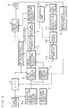
- FIG. 7 is a block diagram showing the configuration of the second embodiment of the electric power steering apparatus of the invention.
- a detection torque signal indicative of the torque detected by the torque sensor 1 is supplied to the CPU 2.
- the CPU 2 receives the detection torque signal, the CPU 2 reads out the target value current corresponding to the detection torque signal from a target value current table (not shown) which is incorporated in the CPU, and differentiates the detection torque signal, and the differential value is added to the target value current (PD control), whereby the motor current target value (magnitude and direction) of the steering force assisting motor 4 is determined.
- a target value current table not shown
- the CPU 2 controls the motor drive circuit 3 with using the motor current target value as a target value of an automatic control, thereby driving the motor 4.
- the driving current of the motor 4 which is detected by a right drive motor current detecting circuit 5a and a left drive motor current detecting circuit 5b is supplied to the CPU 2 as the feedback value of the automatic control.
- the CPU 2 supplies the motor current target value also to a drive logic judging circuit 9a and the motor non-drive detecting circuit 11.
- the detection torque signal from the torque sensor 1 is supplied also to the direction inhibition region judging circuit 8a.
- a predetermined value is for each of the right and left directions.
- the state of the detected torque i.e., whether it is within the predetermined value or not is informed to the drive logic judging circuit 9a and the dead zone detecting circuit 10.
- the detection torque signal from the torque sensor 1 is supplied also to a differentiating circuit 30.
- the differential result of the differentiating circuit 30 is supplied to a torque change direction detecting circuit 31 which in turn detects the change direction of the detected torque.
- a signal indicative of the change direction of the detected torque is supplied to an abnormal current judging circuit 6a and the drive logic judging circuit 9a.
- the dead zone detecting circuit 10 detects the dead zone of the detected torque where the motor current target value is to be zero.
- a detection signal of the dead zone detecting circuit 10 is supplied to the drive logic judging circuit 9a and the abnormal current judging circuit 6a.
- the drive logic judging circuit 9a judges whether the detected torque is outside the dead zone or not, whether the direction in which the motor 4 is to be driven in accordance with the motor current target value is opposite to the direction of the detected torque or not, and whether the direction in which the motor 4 is to be driven in accordance with the motor current target value is opposite to the change direction of the detected torque or not.
- the judgment results of the drive logic judging circuit 9a and the abnormal current judging circuit 6a are supplied to a drive abnormality detecting circuit 7a.
- the detection timer 12 and the definition timer 15 start the timer operations for predetermined times T1 (e.g., 10 msec.) and T2 (e.g., 1 sec.), respectively.
- the latch circuit 16 holds the abnormality detection signal from the drive abnormality detecting circuit 7a.
- the diagnosis lamp 19 is lit and the relay drive inhibiting circuit 17 causes the fail safe relay 18 which connects the motor drive circuit 3 with the power source, to be turned off.
- the torque detected by the torque sensor 1 is supplied to the direction inhibition region judging circuit 8a.
- the direction inhibition region judging circuit 8a judges the direction and magnitude of the detected torque.
- a signal indicative of the direction of the detected torque is sent to the drive logic judging circuit 9a.
- a signal indicative of the magnitudinous relationship with a predetermined value (inside the dead zone or outside the dead zone) in each of the right and left directions as shown in FIG. 8 is sent to the dead zone detecting circuit 10.
- the dead zone detecting circuit 10 supplies a notification signal which indicates whether the detected torque is inside or outside the dead zone, to the drive logic judging circuit 9a and the abnormal current judging circuit 6a.
- the torque detected by the torque sensor 1 is supplied also to the differentiating circuit 30.
- the calculation result of the differentiating circuit 30 is supplied to the torque change direction detecting circuit 31 and the change direction of the detected torque is detected.
- a signal indicative of the change direction of the detected torque is supplied to the abnormal current judging circuit 6a and the drive logic judging circuit 9a.
- the drive abnormality detecting circuit 7a detects the abnormality and activates the detection timer 12 and the definition timer 15, and, when the abnormality notification from the drive logic judging circuit 9a or the abnormal current judging circuit 6a is interrupted, resets the detection timer 12 and the definition timer 15.
- the relationship between the direction in which the motor is to be driven in accordance with the motor current target value and that of the detected torque, and the relationship between the direction in which the motor is driven by the motor driving current and the change direction of the detected torque are added to the conditions for detecting a drive abnormality, whereby the predetermined time T1 of the detection timer 12 can be set to be shorter. Consequently, in the electric power steering apparatus of the second embodiment, when the CPU 2 is normal, the detection timer 12 does not erroneously detect that the CPU 2 runs away, and, when the CPU 2 runs away, the motor 4 can rapidly be turned off.
- the apparatus is not configured so that the latch circuit 13 is not cleared unless the motor non-drive detecting circuit 11 once detects that the motor current target value is zero (non-driven), there arises a problem as discussed below.
- the CPU 2 runs away and the motor current target value becomes excessive, even when the detected torque is inside the dead zone, a large current flows through the motor 4 during the period when the detection timer 12 performs the timer operation for the predetermined time T1, whereby the steering wheel is caused to self-rotate.
- the self-rotation of the steering wheel produces the detected torque the direction of which is opposite to the driving direction of the motor 4 which is driven by the driving current. Therefore, the drive logic judging circuit 9a judges an abnormality and notifies it.
- the detection timer 12 When the CPU 2 detects the non-drive of the motor, the detection timer 12 is reset. Depending on the runaway state of the CPU 2, therefore, the detection and the reset are repeated so that an unstable state may be caused.
- the predetermined time T2 of the definition timer 15 is set so as to be sufficiently longer than the predetermined time T1 of the detection timer 12, and, when a drive abnormality is continued for the predetermined time T2, the fault is determined.
- the drive logic judging circuit 9a judges that the apparatus is normal, and does not notify the drive abnormality detecting circuit 7a of an abnormality.
- the abnormal current judging circuit 6a does not notify the drive abnormality detecting circuit 7a of an abnormality.
- the drive abnormality detecting circuit 7a stops the detection timer 12 and the definition timer 15. Therefore, the latch circuits 13 and 16 do not hold an abnormality notification and hence the motor drive inhibiting circuit 14 and the relay drive inhibiting circuit 17 are not activated.
- the electric power steering apparatus of the second embodiment attains an effect that a runaway of a CPU can be detected in a short time and a sufficient safety countermeasure can be taken.
Landscapes
- Engineering & Computer Science (AREA)
- Chemical & Material Sciences (AREA)
- Combustion & Propulsion (AREA)
- Transportation (AREA)
- Mechanical Engineering (AREA)
- Power Steering Mechanism (AREA)
- Steering Control In Accordance With Driving Conditions (AREA)
Applications Claiming Priority (6)
| Application Number | Priority Date | Filing Date | Title |
|---|---|---|---|
| JP246536/94 | 1994-10-12 | ||
| JP24653694A JP3484617B2 (ja) | 1994-10-12 | 1994-10-12 | 電動パワーステアリング装置 |
| JP24653694 | 1994-10-12 | ||
| JP161177/95 | 1995-06-27 | ||
| JP16117795 | 1995-06-27 | ||
| JP16117795A JP3500517B2 (ja) | 1995-06-27 | 1995-06-27 | 電動パワーステアリング装置 |
Publications (3)
| Publication Number | Publication Date |
|---|---|
| EP0706930A2 true EP0706930A2 (de) | 1996-04-17 |
| EP0706930A3 EP0706930A3 (de) | 1997-07-23 |
| EP0706930B1 EP0706930B1 (de) | 2001-07-04 |
Family
ID=26487407
Family Applications (1)
| Application Number | Title | Priority Date | Filing Date |
|---|---|---|---|
| EP95116104A Expired - Lifetime EP0706930B1 (de) | 1994-10-12 | 1995-10-12 | Elektrische Servolenkung |
Country Status (3)
| Country | Link |
|---|---|
| US (1) | US5720361A (de) |
| EP (1) | EP0706930B1 (de) |
| DE (1) | DE69521581T2 (de) |
Cited By (7)
| Publication number | Priority date | Publication date | Assignee | Title |
|---|---|---|---|---|
| GB2322608A (en) * | 1997-02-28 | 1998-09-02 | Nissan Motor | Steering system for vehicle |
| EP0901217A1 (de) * | 1997-01-23 | 1999-03-10 | Mitsubishi Denki Kabushiki Kaisha | Steuerung für motorischangetriebene servolenkung |
| EP0863065A3 (de) * | 1997-03-04 | 2000-12-13 | Koyo Seiko Co., Ltd. | Elektrische Servolenkung |
| FR2837162A1 (fr) * | 2002-03-11 | 2003-09-19 | Denso Corp | Systeme de commande destine a un dispositif de direction alimente electriquement |
| EP1319576A3 (de) * | 2001-12-17 | 2004-04-07 | Toyoda Koki Kabushiki Kaisha | Steuereinrichtung einer elektrischen Servolenkung |
| EP1452421A2 (de) * | 2003-02-27 | 2004-09-01 | Koyo Seiko Co., Ltd. | Elektrische Servolenkung |
| CN108528525A (zh) * | 2018-04-09 | 2018-09-14 | 江苏农牧科技职业学院 | 一种农用装载车转向控制系统 |
Families Citing this family (12)
| Publication number | Priority date | Publication date | Assignee | Title |
|---|---|---|---|---|
| US5999869A (en) * | 1995-10-12 | 1999-12-07 | Koyo Seiko Co., Ltd. | Electric power steering apparatus |
| JP3391628B2 (ja) * | 1996-04-30 | 2003-03-31 | 三菱電機株式会社 | 電動パワーステアリングの制御装置 |
| JP3285490B2 (ja) * | 1996-05-28 | 2002-05-27 | 三菱電機株式会社 | 電動式パワーステアリング装置 |
| JP3063893B2 (ja) * | 1997-01-07 | 2000-07-12 | 本田技研工業株式会社 | 電動パワーステアリング装置 |
| JP3681259B2 (ja) * | 1997-07-23 | 2005-08-10 | 光洋精工株式会社 | 電動パワーステアリング装置 |
| JP3418098B2 (ja) * | 1997-08-27 | 2003-06-16 | 本田技研工業株式会社 | 電動パワーステアリング装置 |
| JP2000198456A (ja) * | 1998-12-28 | 2000-07-18 | Honda Motor Co Ltd | 電動パワ―ステアリング装置 |
| US6226592B1 (en) * | 1999-03-22 | 2001-05-01 | Veridian Erim International, Inc. | Method and apparatus for prompting a motor vehicle operator to remain within a lane |
| JP3486749B2 (ja) * | 2000-04-05 | 2004-01-13 | 本田技研工業株式会社 | 電動パワーステアリング装置 |
| JP4461615B2 (ja) * | 2000-12-13 | 2010-05-12 | 株式会社デンソー | 電動パワーステアリング機構の制御装置 |
| EP1666339B1 (de) * | 2003-08-28 | 2018-12-05 | NSK Ltd. | Steuerung für elektrische servolenkungsvorrichtungen |
| TWI384748B (zh) * | 2009-04-03 | 2013-02-01 | Anpec Electronics Corp | 用於一馬達之驅動方法及其相關驅動裝置 |
Family Cites Families (3)
| Publication number | Priority date | Publication date | Assignee | Title |
|---|---|---|---|---|
| EP0638470B1 (de) * | 1991-10-10 | 1997-01-22 | Koyo Seiko Co., Ltd. | Elektrische Servolenkung |
| EP0631922B1 (de) * | 1993-07-02 | 1997-03-05 | Koyo Seiko Co., Ltd. | Elektrische Servolenkung |
| JP2932335B2 (ja) * | 1993-07-30 | 1999-08-09 | 光洋精工株式会社 | 電動パワーステアリング装置 |
-
1995
- 1995-10-12 US US08/542,252 patent/US5720361A/en not_active Expired - Lifetime
- 1995-10-12 EP EP95116104A patent/EP0706930B1/de not_active Expired - Lifetime
- 1995-10-12 DE DE69521581T patent/DE69521581T2/de not_active Expired - Lifetime
Non-Patent Citations (1)
| Title |
|---|
| None |
Cited By (13)
| Publication number | Priority date | Publication date | Assignee | Title |
|---|---|---|---|---|
| EP0901217A4 (de) * | 1997-01-23 | 2005-03-23 | Mitsubishi Electric Corp | Regler für motorisch-angetriebene servolenkung |
| EP0901217A1 (de) * | 1997-01-23 | 1999-03-10 | Mitsubishi Denki Kabushiki Kaisha | Steuerung für motorischangetriebene servolenkung |
| EP1764905A1 (de) * | 1997-01-23 | 2007-03-21 | Mitsubishi Denki Kabushiki Kaisha | Steuerung für eine motorbetriebene Servolenkung |
| GB2322608B (en) * | 1997-02-28 | 1999-02-24 | Nissan Motor | Steering system for vehicle |
| US6050359A (en) * | 1997-02-28 | 2000-04-18 | Nissan Motor Co., Ltd. | Steering system for vehicle |
| GB2322608A (en) * | 1997-02-28 | 1998-09-02 | Nissan Motor | Steering system for vehicle |
| EP0863065A3 (de) * | 1997-03-04 | 2000-12-13 | Koyo Seiko Co., Ltd. | Elektrische Servolenkung |
| EP1319576A3 (de) * | 2001-12-17 | 2004-04-07 | Toyoda Koki Kabushiki Kaisha | Steuereinrichtung einer elektrischen Servolenkung |
| FR2837162A1 (fr) * | 2002-03-11 | 2003-09-19 | Denso Corp | Systeme de commande destine a un dispositif de direction alimente electriquement |
| EP1452421A2 (de) * | 2003-02-27 | 2004-09-01 | Koyo Seiko Co., Ltd. | Elektrische Servolenkung |
| EP1452421A3 (de) * | 2003-02-27 | 2005-12-21 | Koyo Seiko Co., Ltd. | Elektrische Servolenkung |
| CN108528525A (zh) * | 2018-04-09 | 2018-09-14 | 江苏农牧科技职业学院 | 一种农用装载车转向控制系统 |
| CN108528525B (zh) * | 2018-04-09 | 2019-04-09 | 江苏农牧科技职业学院 | 一种农用装载车转向控制系统 |
Also Published As
| Publication number | Publication date |
|---|---|
| DE69521581T2 (de) | 2002-05-29 |
| DE69521581D1 (de) | 2001-08-09 |
| US5720361A (en) | 1998-02-24 |
| EP0706930A3 (de) | 1997-07-23 |
| EP0706930B1 (de) | 2001-07-04 |
Similar Documents
| Publication | Publication Date | Title |
|---|---|---|
| EP0706930B1 (de) | Elektrische Servolenkung | |
| EP0638470B1 (de) | Elektrische Servolenkung | |
| US5360077A (en) | Electric power steering apparatus | |
| KR0178294B1 (ko) | 전동파워스티어링 제어장치 | |
| JP3511593B2 (ja) | 電動パワーステアリング制御装置 | |
| US5271474A (en) | Electric power steering apparatus | |
| US6704632B2 (en) | Controller for vehicle steering apparatus and method for detecting abnormality in the controller | |
| US5552684A (en) | Control apparatus for reversible motor and motor-driven power steering system for motor vehicle using the same | |
| EP0522492A2 (de) | Lenkung mit elektrischer Hilfskraft | |
| JP2007134780A (ja) | 自己診断機能を備えた負荷駆動装置 | |
| US6513619B2 (en) | Electrically-driven power steering system | |
| JPH0674024B2 (ja) | 自動車のドライバー拘束システムの制御装置 | |
| US4834201A (en) | Electrical power steering apparatus | |
| US4961144A (en) | Self-check method of four-wheel steering drive system | |
| JP5496257B2 (ja) | 電動パワーステアリング制御装置 | |
| JP3096793B2 (ja) | 電動パワーステアリング装置 | |
| US4569411A (en) | Power steering control apparatus | |
| JP3484617B2 (ja) | 電動パワーステアリング装置 | |
| JPH0520976U (ja) | 電動パワーステアリング装置 | |
| JPS61169366A (ja) | 電動式パワ−ステアリング制御装置 | |
| JP3007932B2 (ja) | 電動パワーステアリング装置 | |
| JP2004129382A (ja) | モータの制御装置 | |
| JP2863971B2 (ja) | 負荷駆動方法 | |
| JPH0446867A (ja) | 電動式パワーステアリング装置 | |
| JP3096792B2 (ja) | 電動パワーステアリング装置 |
Legal Events
| Date | Code | Title | Description |
|---|---|---|---|
| PUAI | Public reference made under article 153(3) epc to a published international application that has entered the european phase |
Free format text: ORIGINAL CODE: 0009012 |
|
| AK | Designated contracting states |
Kind code of ref document: A2 Designated state(s): DE FR GB IT |
|
| PUAL | Search report despatched |
Free format text: ORIGINAL CODE: 0009013 |
|
| AK | Designated contracting states |
Kind code of ref document: A3 Designated state(s): DE FR GB IT |
|
| 17P | Request for examination filed |
Effective date: 19970827 |
|
| 17Q | First examination report despatched |
Effective date: 19991222 |
|
| GRAG | Despatch of communication of intention to grant |
Free format text: ORIGINAL CODE: EPIDOS AGRA |
|
| GRAG | Despatch of communication of intention to grant |
Free format text: ORIGINAL CODE: EPIDOS AGRA |
|
| GRAH | Despatch of communication of intention to grant a patent |
Free format text: ORIGINAL CODE: EPIDOS IGRA |
|
| GRAH | Despatch of communication of intention to grant a patent |
Free format text: ORIGINAL CODE: EPIDOS IGRA |
|
| GRAA | (expected) grant |
Free format text: ORIGINAL CODE: 0009210 |
|
| AK | Designated contracting states |
Kind code of ref document: B1 Designated state(s): DE FR GB IT |
|
| REF | Corresponds to: |
Ref document number: 69521581 Country of ref document: DE Date of ref document: 20010809 |
|
| ITF | It: translation for a ep patent filed |
Owner name: STUDIO TORTA S.R.L. |
|
| ET | Fr: translation filed | ||
| REG | Reference to a national code |
Ref country code: GB Ref legal event code: IF02 |
|
| PLBE | No opposition filed within time limit |
Free format text: ORIGINAL CODE: 0009261 |
|
| STAA | Information on the status of an ep patent application or granted ep patent |
Free format text: STATUS: NO OPPOSITION FILED WITHIN TIME LIMIT |
|
| 26N | No opposition filed | ||
| PGFP | Annual fee paid to national office [announced via postgrant information from national office to epo] |
Ref country code: IT Payment date: 20071026 Year of fee payment: 13 |
|
| PGFP | Annual fee paid to national office [announced via postgrant information from national office to epo] |
Ref country code: GB Payment date: 20071010 Year of fee payment: 13 |
|
| GBPC | Gb: european patent ceased through non-payment of renewal fee |
Effective date: 20081012 |
|
| PG25 | Lapsed in a contracting state [announced via postgrant information from national office to epo] |
Ref country code: IT Free format text: LAPSE BECAUSE OF NON-PAYMENT OF DUE FEES Effective date: 20081012 |
|
| PG25 | Lapsed in a contracting state [announced via postgrant information from national office to epo] |
Ref country code: GB Free format text: LAPSE BECAUSE OF NON-PAYMENT OF DUE FEES Effective date: 20081012 |
|
| PGFP | Annual fee paid to national office [announced via postgrant information from national office to epo] |
Ref country code: FR Payment date: 20141008 Year of fee payment: 20 Ref country code: DE Payment date: 20141007 Year of fee payment: 20 |
|
| REG | Reference to a national code |
Ref country code: DE Ref legal event code: R071 Ref document number: 69521581 Country of ref document: DE |