EP0706919A1 - Lenkradschloss für Kraftfahrzeuge mit einem Automatikgetriebe - Google Patents
Lenkradschloss für Kraftfahrzeuge mit einem Automatikgetriebe Download PDFInfo
- Publication number
- EP0706919A1 EP0706919A1 EP95115616A EP95115616A EP0706919A1 EP 0706919 A1 EP0706919 A1 EP 0706919A1 EP 95115616 A EP95115616 A EP 95115616A EP 95115616 A EP95115616 A EP 95115616A EP 0706919 A1 EP0706919 A1 EP 0706919A1
- Authority
- EP
- European Patent Office
- Prior art keywords
- pusher
- movable core
- steering lock
- electromagnet
- lock according
- Prior art date
- Legal status (The legal status is an assumption and is not a legal conclusion. Google has not performed a legal analysis and makes no representation as to the accuracy of the status listed.)
- Granted
Links
- 230000005540 biological transmission Effects 0.000 title 1
- 230000000903 blocking effect Effects 0.000 claims description 6
- 230000006835 compression Effects 0.000 description 2
- 238000007906 compression Methods 0.000 description 2
- 208000031968 Cadaver Diseases 0.000 description 1
- 230000000295 complement effect Effects 0.000 description 1
- 238000000034 method Methods 0.000 description 1
- 238000000465 moulding Methods 0.000 description 1
- 230000000717 retained effect Effects 0.000 description 1
- 239000007787 solid Substances 0.000 description 1
Images


Classifications
-
- B—PERFORMING OPERATIONS; TRANSPORTING
- B60—VEHICLES IN GENERAL
- B60R—VEHICLES, VEHICLE FITTINGS, OR VEHICLE PARTS, NOT OTHERWISE PROVIDED FOR
- B60R25/00—Fittings or systems for preventing or indicating unauthorised use or theft of vehicles
- B60R25/01—Fittings or systems for preventing or indicating unauthorised use or theft of vehicles operating on vehicle systems or fittings, e.g. on doors, seats or windscreens
- B60R25/02—Fittings or systems for preventing or indicating unauthorised use or theft of vehicles operating on vehicle systems or fittings, e.g. on doors, seats or windscreens operating on the steering mechanism
- B60R25/021—Fittings or systems for preventing or indicating unauthorised use or theft of vehicles operating on vehicle systems or fittings, e.g. on doors, seats or windscreens operating on the steering mechanism restraining movement of the steering column or steering wheel hub, e.g. restraining means controlled by ignition switch
- B60R25/02142—Fittings or systems for preventing or indicating unauthorised use or theft of vehicles operating on vehicle systems or fittings, e.g. on doors, seats or windscreens operating on the steering mechanism restraining movement of the steering column or steering wheel hub, e.g. restraining means controlled by ignition switch comprising externally controlled safety devices for preventing locking during vehicle running condition
- B60R25/02144—Fittings or systems for preventing or indicating unauthorised use or theft of vehicles operating on vehicle systems or fittings, e.g. on doors, seats or windscreens operating on the steering mechanism restraining movement of the steering column or steering wheel hub, e.g. restraining means controlled by ignition switch comprising externally controlled safety devices for preventing locking during vehicle running condition interlocked with gear box or gear lever
-
- F—MECHANICAL ENGINEERING; LIGHTING; HEATING; WEAPONS; BLASTING
- F16—ENGINEERING ELEMENTS AND UNITS; GENERAL MEASURES FOR PRODUCING AND MAINTAINING EFFECTIVE FUNCTIONING OF MACHINES OR INSTALLATIONS; THERMAL INSULATION IN GENERAL
- F16H—GEARING
- F16H61/00—Control functions within control units of change-speed- or reversing-gearings for conveying rotary motion ; Control of exclusively fluid gearing, friction gearing, gearings with endless flexible members or other particular types of gearing
- F16H61/22—Locking of the control input devices
- F16H2061/223—Electrical gear shift lock, e.g. locking of lever in park or neutral position by electric means if brake is not applied; Key interlock, i.e. locking the key if lever is not in park position
Definitions
- the present invention relates to a steering lock for a motor vehicle.
- the invention relates more particularly to an anti-theft device for a motor vehicle equipped with an automatic gearbox, the control of which is ensured by means of a lever capable of occupying a rest position, in particular a parking position, which is detected by a sensor whose output signal is the control parameter of an electromagnet whose movable core ensures the rotation blocking of a rotary member of an anti-theft lock when the lever does not occupy the rest position , and of the type in which the movable core is resiliently biased by a return spring towards its extended position for blocking the rotary member of the lock.
- Such an anti-theft design makes it possible, in association with an automatic gearbox, to prevent the driver from stopping his vehicle and leaving it without having put the gearshift lever in the parking position.
- the lock of the lock remains locked in an angular position, also called accessory position, in which it cannot extract the key out of the lock.
- an electronic control circuit then transmits an output signal to the electromagnet which causes the withdrawal of the movable core against the 'force applied to it by the return spring and the driver can then freely rotate the barrel of the lock to the "stop" position in which he can extract the key from the lock.
- an anti-theft device of the type mentioned above of the type comprising a manual control member for the withdrawal of the movable core against the elastic return force.
- the driver can act mechanically on the control member to cause the removal or erasure of the movable core against the force applied to it by the return spring and turn then the key in the stop position in order to be able to extract the latter.
- such a control member is produced in the form of an articulated lever or rocker whose design is complex, costly and whose manipulation by the driver is not very easy.
- the object of the present invention is to propose a new design of an anti-theft device of the type mentioned above which overcomes these drawbacks.
- the invention provides an anti-theft device characterized in that the manual control member is a pusher mounted sliding in a direction perpendicular to the direction of movement of the mobile core and which comprises an inclined ramp which cooperates with a shoulder formed on the moving core.
- FIGS. 1 and 2 show a box 10 intended to be associated with the box for guiding in rotation of the steering column (not shown) which is of generally cylindrical shape and of which an internal bore 12 receives, fixed in rotation and in axial translation, a stator 14 of a lock 16.
- the stator 14 is an element of generally cylindrical annular shape, a first front part, on the left when considering FIG. 2, is arranged in the bore 12, and a second rear part 18 of which is arranged outside the bore 12.
- the housing 10 also comprises a passage 20 forming a slide and which receives in sliding, in an axial direction parallel to the axis of the bore 12 and of the stator 14, a bolt locking device 22 which is slidably mounted between its retracted position illustrated in FIG. 2 in which its front end 26 is set back relative to the cylindrical end face 28 of the part of the housing 10 intended to cooperate with a tube of the column direction, and a locking position (not shown in the figures) in which its front end 26 projects outside the passage 22 to be received in a housing (not shown) of the steering shaft.
- the bolt 22 is connected in axial translation to a pull tab 30 which is slidably received in a guide slot formed in the front part of the stator 14.
- a locking spring 32 biases the bolt 22 axially towards its locking position by acting on a reaction tab 34 formed on the pull tab 30.
- the pull tab 30 and the bolt 22 are thus permanently biased axially forwards in the locking position of the steering column.
- a rotary control member 36 comprising in particular a control cam which cooperates with a control finger connected to the pull tab.
- the rotary actuating member 36 has a generally cylindrical shape and is rotatably mounted in the stator 14 to be rotated by the rotor or barrel 38 of the lock 16 when the corresponding key is introduced into the lock through an opening 40 formed at the right end of the latter.
- the anti-theft device 10 illustrated in FIGS. 1 and 2 is intended to equip a motor vehicle provided with an automatic gearbox.
- the gearshift lever (not shown) is in a rest position called the parking position.
- an electromagnet 42 whose electrical supply is controlled by a control circuit (not shown) as a function of a signal which is transmitted to it by a sensor for whether or not the gearshift lever is in the parking position.
- the coil of the electromagnet 42 is not energized.
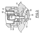
- the lower end 48 of the body 46 of the electromagnet 42 is received in a housing 50 produced integrally by molding with the housing of the anti-theft device 10 and which is arranged at the vertical above a cylindrical surface portion 52 of the rotary drive member 36.
- the free end portion in the form of a cylindrical rod 54 of the movable core 44 is capable of projecting radially inside the stator 14 through an opening 56 formed in the latter and through an opening 58 formed in the wall portion facing the housing 10.
- the movable core 44 of the electromagnet is permanently resiliently stressed by a helical compression spring 60 which biases the movable core vertically downwards considering Figures 2 to 5, c ' that is to say towards an output position of the movable core when the electromagnet 42 is not supplied with current.
- the free end portion in the form of a cylindrical rod 54 which passes through the holes 56 and 58 is thus capable of being received in a locking notch 62 formed in the cylindrical wall 52 of the rotary actuating member 36.
- the notch 62 is delimited by a radial abutment surface 64 and by a surface 66 allowing the end 54 of the movable core 44 to be released from the notch 62, against the force exerted by the spring 60 when the rotary drive member 36 linked to the rotor of the latch 16 rotates counterclockwise when considering FIG. 3.
- the fixing of the electromagnet in the housing 50 is ensured by means of a fixing cover 68 which is resiliently fitted on the part 51 of the anti-theft housing 10 in which the housing 50 is formed by lugs 70 which are received in holes 72 formed in the lower part 74 of the cover 68.
- the housing part 51 also comprises a slide 76 which is open at its two ends and which receives in axial sliding, in a direction parallel to the general axis of the latch 16, the body 78 of a pusher 80 for unlocking the movable core 44.
- the body 78 of the pusher 80 is essentially constituted by two parallel lateral cheeks 82 which delimit between them a longitudinal slot 84 and which are connected together at one end by a transverse connecting edge 86 and at the other end by a solid part 88 constituting an actuating head of the pusher 80.
- the two cheeks 82 are connected by a complementary part which delimits a semi-cylindrical longitudinal housing 90 which serves as a guide for a helical compression return spring 92 which bears at one of its ends against the head 88 and at the other end against a corresponding part of the portion 51 of the housing 10.
- the spring 92 permanently resiliently urges the pusher 80 towards its rest position illustrated in particular in FIG. 2 in which it is retained in position by a retaining spout 94 formed on an extension 96 of the lower part 74 of the cover 68 of retaining retaining the electromagnet 12 which extends through the slot 84.
- the two lateral cheeks 82 each have an inclined ramp 98 which is capable of cooperating, as will be explained below, with a frustoconical shoulder 100 of the movable core 44 of the electromagnet 42 .
- the electromagnet 42 is electrically powered and the control lever of the automatic gearbox is in the parking position.
- the movable core 44 is in its erased position, also called withdrawal position, vertically upwards towards which it is electromagnetically recalled by the coil 46 of the electromagnet 42 against the force applied to it by the spring 60 which is compressed.
- the mobile core or plunger 44 of the electromagnet 42 is in contact, by its free end rod 54 with the external cylindrical surface 52 of the rotary control member 36 .
- the driver can release the plunger, the end 54 of the plunger 44 then coming into contact with the cylindrical surface 52 of the rotary drive member 36 thus making it possible the command again to start the vehicle by means of the latch 14.
Landscapes
- Engineering & Computer Science (AREA)
- Mechanical Engineering (AREA)
- Arrangement Or Mounting Of Control Devices For Change-Speed Gearing (AREA)
- Lock And Its Accessories (AREA)
- Steering Control In Accordance With Driving Conditions (AREA)
- Control Of Transmission Device (AREA)
Applications Claiming Priority (2)
| Application Number | Priority Date | Filing Date | Title |
|---|---|---|---|
| FR9412142 | 1994-10-10 | ||
| FR9412142A FR2725413B1 (fr) | 1994-10-10 | 1994-10-10 | Antivol de direction pour un vehicule automobile equipe d'une boite de vitesses automatique. |
Publications (3)
| Publication Number | Publication Date |
|---|---|
| EP0706919A1 true EP0706919A1 (de) | 1996-04-17 |
| EP0706919B1 EP0706919B1 (de) | 1998-06-10 |
| EP0706919B2 EP0706919B2 (de) | 2002-04-10 |
Family
ID=9467767
Family Applications (1)
| Application Number | Title | Priority Date | Filing Date |
|---|---|---|---|
| EP19950115616 Expired - Lifetime EP0706919B2 (de) | 1994-10-10 | 1995-10-04 | Lenkradschloss für Kraftfahrzeuge mit einem Automatikgetriebe |
Country Status (4)
| Country | Link |
|---|---|
| EP (1) | EP0706919B2 (de) |
| DE (1) | DE69502904T3 (de) |
| ES (1) | ES2117342T5 (de) |
| FR (1) | FR2725413B1 (de) |
Cited By (5)
| Publication number | Priority date | Publication date | Assignee | Title |
|---|---|---|---|---|
| WO2001089888A1 (de) * | 2000-05-24 | 2001-11-29 | Delphi Technologies Inc. | Abziehsperre für einen schlüssel aus einem zündanlassschalter eines kraftfahrzeuges |
| WO2002092404A1 (de) * | 2001-05-15 | 2002-11-21 | Leopold Kostal Gmbh & Co. Kg | Manuell betätigbarer zündanlassschalter für eine schlüsssellose motorstartberechtigungskontrolleinrichtung eines kraftfahrzeuges |
| FR2828857A1 (fr) * | 2001-08-24 | 2003-02-28 | Tokai Rika Co Ltd | Dispositif electronique antivol pour automobile |
| WO2003022646A1 (de) * | 2001-09-10 | 2003-03-20 | Leopold Kostal Gmbh & Co. Kg | Zündanlassschalter |
| US20140124282A1 (en) * | 2011-01-21 | 2014-05-08 | Valeo Sicherheitssysteme Gmbh | Antitheft device for the steering mechanism of a motor vehicle |
Families Citing this family (1)
| Publication number | Priority date | Publication date | Assignee | Title |
|---|---|---|---|---|
| DE19957546C2 (de) * | 1999-11-30 | 2002-02-07 | Huf Huelsbeck & Fuerst Gmbh | Lenkschloß für Kraftfahrzeuge |
Citations (8)
| Publication number | Priority date | Publication date | Assignee | Title |
|---|---|---|---|---|
| US3688861A (en) * | 1969-05-07 | 1972-09-05 | Brevets Neiman Sa Soc D Expl D | Anti-theft devices |
| US3887029A (en) * | 1970-06-19 | 1975-06-03 | Des Brevets Neiman Soc D Expl | Anti-theft devices |
| DE8802327U1 (de) * | 1988-02-23 | 1988-04-14 | Tibbe KG, 8065 Erdweg | Lenkschloß für Kraftfahrzeuge mit automatischem Getriebe |
| GB2211545A (en) * | 1987-12-19 | 1989-07-05 | Honda Lock Mfg Co Ltd | Vehicle steering lock control device |
| EP0336219A2 (de) * | 1988-04-01 | 1989-10-11 | Kabushiki Kaisha Tokai-Rika-Denki-Seisakusho | Lenkungverriegelungsvorrichtung |
| JPH02283962A (ja) * | 1989-04-24 | 1990-11-21 | Mazda Motor Corp | 自動変速機の操作装置 |
| US5065604A (en) * | 1990-06-11 | 1991-11-19 | Sparton Corporation | Ignition interlock system |
| DE4206251A1 (de) * | 1991-03-13 | 1992-09-17 | Volkswagen Ag | Sicherheitsvorrichtung fuer ein kraftfahrzeug mit einem getriebe und einem lenkschloss |
Family Cites Families (5)
| Publication number | Priority date | Publication date | Assignee | Title |
|---|---|---|---|---|
| DE6914368U (de) * | 1969-04-10 | 1969-08-07 | Neiman & Co K G | Zusatzsicherung im schliesszylinder, insbesondere bei diebstahlsicherungen fuer kraftfahrzeuge |
| JPS4911908B1 (de) * | 1969-12-06 | 1974-03-20 | ||
| JPS54170546U (de) * | 1978-05-22 | 1979-12-01 | ||
| JPH02125871U (de) * | 1989-03-28 | 1990-10-17 | ||
| US5096033A (en) * | 1991-01-17 | 1992-03-17 | Grand Haven Stamped Products Company | Lockout mechanism and system for vehicle shifter |
-
1994
- 1994-10-10 FR FR9412142A patent/FR2725413B1/fr not_active Expired - Lifetime
-
1995
- 1995-10-04 EP EP19950115616 patent/EP0706919B2/de not_active Expired - Lifetime
- 1995-10-04 DE DE1995602904 patent/DE69502904T3/de not_active Expired - Lifetime
- 1995-10-04 ES ES95115616T patent/ES2117342T5/es not_active Expired - Lifetime
Patent Citations (8)
| Publication number | Priority date | Publication date | Assignee | Title |
|---|---|---|---|---|
| US3688861A (en) * | 1969-05-07 | 1972-09-05 | Brevets Neiman Sa Soc D Expl D | Anti-theft devices |
| US3887029A (en) * | 1970-06-19 | 1975-06-03 | Des Brevets Neiman Soc D Expl | Anti-theft devices |
| GB2211545A (en) * | 1987-12-19 | 1989-07-05 | Honda Lock Mfg Co Ltd | Vehicle steering lock control device |
| DE8802327U1 (de) * | 1988-02-23 | 1988-04-14 | Tibbe KG, 8065 Erdweg | Lenkschloß für Kraftfahrzeuge mit automatischem Getriebe |
| EP0336219A2 (de) * | 1988-04-01 | 1989-10-11 | Kabushiki Kaisha Tokai-Rika-Denki-Seisakusho | Lenkungverriegelungsvorrichtung |
| JPH02283962A (ja) * | 1989-04-24 | 1990-11-21 | Mazda Motor Corp | 自動変速機の操作装置 |
| US5065604A (en) * | 1990-06-11 | 1991-11-19 | Sparton Corporation | Ignition interlock system |
| DE4206251A1 (de) * | 1991-03-13 | 1992-09-17 | Volkswagen Ag | Sicherheitsvorrichtung fuer ein kraftfahrzeug mit einem getriebe und einem lenkschloss |
Non-Patent Citations (1)
| Title |
|---|
| PATENT ABSTRACTS OF JAPAN vol. 15, no. 49 (M - 1079) 24 April 1989 (1989-04-24) * |
Cited By (7)
| Publication number | Priority date | Publication date | Assignee | Title |
|---|---|---|---|---|
| WO2001089888A1 (de) * | 2000-05-24 | 2001-11-29 | Delphi Technologies Inc. | Abziehsperre für einen schlüssel aus einem zündanlassschalter eines kraftfahrzeuges |
| WO2002092404A1 (de) * | 2001-05-15 | 2002-11-21 | Leopold Kostal Gmbh & Co. Kg | Manuell betätigbarer zündanlassschalter für eine schlüsssellose motorstartberechtigungskontrolleinrichtung eines kraftfahrzeuges |
| FR2828857A1 (fr) * | 2001-08-24 | 2003-02-28 | Tokai Rika Co Ltd | Dispositif electronique antivol pour automobile |
| US6998731B2 (en) | 2001-08-24 | 2006-02-14 | Kabushiki Kaisha Tokai Rika Denki Seisakusho | Electronic automotive anti-theft device |
| WO2003022646A1 (de) * | 2001-09-10 | 2003-03-20 | Leopold Kostal Gmbh & Co. Kg | Zündanlassschalter |
| US20140124282A1 (en) * | 2011-01-21 | 2014-05-08 | Valeo Sicherheitssysteme Gmbh | Antitheft device for the steering mechanism of a motor vehicle |
| US8978811B2 (en) * | 2011-01-21 | 2015-03-17 | Valeo Sicherheitssysteme Gmbh | Antitheft device for the steering mechanism of a motor vehicle |
Also Published As
| Publication number | Publication date |
|---|---|
| DE69502904T2 (de) | 1998-10-08 |
| DE69502904D1 (de) | 1998-07-16 |
| ES2117342T5 (es) | 2002-11-01 |
| EP0706919B1 (de) | 1998-06-10 |
| FR2725413B1 (fr) | 1996-11-29 |
| EP0706919B2 (de) | 2002-04-10 |
| ES2117342T3 (es) | 1998-08-01 |
| FR2725413A1 (fr) | 1996-04-12 |
| DE69502904T3 (de) | 2002-09-12 |
Similar Documents
| Publication | Publication Date | Title |
|---|---|---|
| EP1020336A1 (de) | Kraftfahrzeuglenkungs- Diebstahlsicherung | |
| EP1863989B1 (de) | Schloss mit einem einzigen schalter | |
| EP1127758A1 (de) | Elektronisches Diebstahlsicherungssystem für Kraftfahrzeuge | |
| FR2807373A1 (fr) | Antivol de vehicule automobile comportant des moyens perfectionnes de retenue du pene | |
| EP1084915A1 (de) | Kraftfahrzeuglenkungsdiebstahlsicherung | |
| FR2679504A1 (fr) | Serrure de blocage de la direction d'un vehicule. | |
| EP0669234B1 (de) | Lenkradschloss für Kraftfahrzeuge mit Sperrvorrichtung des Riegelverschlusses | |
| FR2788479A1 (fr) | Dispositif d'antivol comportant un interrupteur electrique pour la detection de l'introduction d'une clef | |
| EP0706919B1 (de) | Lenkradschloss für Kraftfahrzeuge mit einem Automatikgetriebe | |
| FR2808552A1 (fr) | Serrure a deverrouillage mecanique et electrique | |
| EP1569828B1 (de) | Diebstahlvorrichtung, insbesondere eine elektronische, für ein kraftfahrzeug | |
| EP0731006B1 (de) | Lenkradschloss für Kraftfahrzeug | |
| EP0596762B1 (de) | Lenkdiebstahl-Schutzvorrichtung für Kraftfahrzeuge und Schlüssel für derartige Vorrichtung | |
| FR2780012A1 (fr) | Antivol de direction | |
| EP2704926B1 (de) | Diebstahlschutzvorrichtung für lenksäule und entsprechende lenksäule | |
| FR2814418A1 (fr) | Ensemble pour vehicule automobile destine a echanger des donnees dont certaines sont representatives d'au moins un utilisateur autorise du vehicule | |
| EP1091314B1 (de) | System zur blockierung eines Datenträgers in einer Datenaustauschvorrichtung und zur Motorstartberechtigung eines Fahrzeuges | |
| FR2743837A1 (fr) | Pene demi-tour pour serrure reversible et serrure reversible comportant un tel pene | |
| EP1043204A1 (de) | Verbesserte Kraftfahrzeugdiebstahlsicherung | |
| EP1502829B1 (de) | Elektronische Steuer- und Diebstahlvorrichtung für ein Kraftfahrzeug mit dieser Vorrichtung | |
| FR2613676A1 (fr) | Dispositif de verrouillage de direction, notamment permettant de deverrouiller l'arbre de direction d'un vehicule a roues, avec et sans cle | |
| EP1193644B1 (de) | System zum Austausch von Daten zur Authorisation eines KFZ-Benutzers | |
| FR2498541A1 (fr) | Perfectionnements aux antivols pour vehicules automobiles | |
| EP1043203A1 (de) | Fahrzeugdiebstahlsicherung | |
| FR2816267A3 (fr) | Dispositif de commande a cle et unite de commande de demarrage d'un moteur de vehicule automobile comprenant ce dispositif |
Legal Events
| Date | Code | Title | Description |
|---|---|---|---|
| PUAI | Public reference made under article 153(3) epc to a published international application that has entered the european phase |
Free format text: ORIGINAL CODE: 0009012 |
|
| AK | Designated contracting states |
Kind code of ref document: A1 Designated state(s): DE ES GB IT |
|
| 17P | Request for examination filed |
Effective date: 19960926 |
|
| GRAG | Despatch of communication of intention to grant |
Free format text: ORIGINAL CODE: EPIDOS AGRA |
|
| GRAG | Despatch of communication of intention to grant |
Free format text: ORIGINAL CODE: EPIDOS AGRA |
|
| GRAH | Despatch of communication of intention to grant a patent |
Free format text: ORIGINAL CODE: EPIDOS IGRA |
|
| 17Q | First examination report despatched |
Effective date: 19971125 |
|
| GRAH | Despatch of communication of intention to grant a patent |
Free format text: ORIGINAL CODE: EPIDOS IGRA |
|
| GRAA | (expected) grant |
Free format text: ORIGINAL CODE: 0009210 |
|
| AK | Designated contracting states |
Kind code of ref document: B1 Designated state(s): DE ES GB IT |
|
| GBT | Gb: translation of ep patent filed (gb section 77(6)(a)/1977) |
Effective date: 19980619 |
|
| REF | Corresponds to: |
Ref document number: 69502904 Country of ref document: DE Date of ref document: 19980716 |
|
| ITF | It: translation for a ep patent filed | ||
| REG | Reference to a national code |
Ref country code: ES Ref legal event code: FG2A Ref document number: 2117342 Country of ref document: ES Kind code of ref document: T3 |
|
| PLBQ | Unpublished change to opponent data |
Free format text: ORIGINAL CODE: EPIDOS OPPO |
|
| PLBI | Opposition filed |
Free format text: ORIGINAL CODE: 0009260 |
|
| PLBF | Reply of patent proprietor to notice(s) of opposition |
Free format text: ORIGINAL CODE: EPIDOS OBSO |
|
| 26 | Opposition filed |
Opponent name: HUF HUELSBECK & FUERST GMBH. & CO. KG. Effective date: 19990305 |
|
| PLBF | Reply of patent proprietor to notice(s) of opposition |
Free format text: ORIGINAL CODE: EPIDOS OBSO |
|
| PLBF | Reply of patent proprietor to notice(s) of opposition |
Free format text: ORIGINAL CODE: EPIDOS OBSO |
|
| PLBF | Reply of patent proprietor to notice(s) of opposition |
Free format text: ORIGINAL CODE: EPIDOS OBSO |
|
| PLAW | Interlocutory decision in opposition |
Free format text: ORIGINAL CODE: EPIDOS IDOP |
|
| APAC | Appeal dossier modified |
Free format text: ORIGINAL CODE: EPIDOS NOAPO |
|
| APAE | Appeal reference modified |
Free format text: ORIGINAL CODE: EPIDOS REFNO |
|
| APAC | Appeal dossier modified |
Free format text: ORIGINAL CODE: EPIDOS NOAPO |
|
| PLAW | Interlocutory decision in opposition |
Free format text: ORIGINAL CODE: EPIDOS IDOP |
|
| REG | Reference to a national code |
Ref country code: GB Ref legal event code: IF02 |
|
| PUAH | Patent maintained in amended form |
Free format text: ORIGINAL CODE: 0009272 |
|
| STAA | Information on the status of an ep patent application or granted ep patent |
Free format text: STATUS: PATENT MAINTAINED AS AMENDED |
|
| 27A | Patent maintained in amended form |
Effective date: 20020410 |
|
| AK | Designated contracting states |
Kind code of ref document: B2 Designated state(s): DE ES GB IT |
|
| GBTA | Gb: translation of amended ep patent filed (gb section 77(6)(b)/1977) | ||
| REG | Reference to a national code |
Ref country code: ES Ref legal event code: DC2A Kind code of ref document: T5 Effective date: 20020613 |
|
| APAH | Appeal reference modified |
Free format text: ORIGINAL CODE: EPIDOSCREFNO |
|
| PGFP | Annual fee paid to national office [announced via postgrant information from national office to epo] |
Ref country code: DE Payment date: 20121011 Year of fee payment: 18 |
|
| PGFP | Annual fee paid to national office [announced via postgrant information from national office to epo] |
Ref country code: ES Payment date: 20121022 Year of fee payment: 18 Ref country code: GB Payment date: 20121023 Year of fee payment: 18 Ref country code: IT Payment date: 20121023 Year of fee payment: 18 |
|
| GBPC | Gb: european patent ceased through non-payment of renewal fee |
Effective date: 20131004 |
|
| REG | Reference to a national code |
Ref country code: DE Ref legal event code: R119 Ref document number: 69502904 Country of ref document: DE Effective date: 20140501 |
|
| PG25 | Lapsed in a contracting state [announced via postgrant information from national office to epo] |
Ref country code: GB Free format text: LAPSE BECAUSE OF NON-PAYMENT OF DUE FEES Effective date: 20131004 |
|
| PG25 | Lapsed in a contracting state [announced via postgrant information from national office to epo] |
Ref country code: DE Free format text: LAPSE BECAUSE OF NON-PAYMENT OF DUE FEES Effective date: 20140501 Ref country code: IT Free format text: LAPSE BECAUSE OF NON-PAYMENT OF DUE FEES Effective date: 20131004 |
|
| REG | Reference to a national code |
Ref country code: ES Ref legal event code: FD2A Effective date: 20141107 |
|
| PG25 | Lapsed in a contracting state [announced via postgrant information from national office to epo] |
Ref country code: ES Free format text: LAPSE BECAUSE OF NON-PAYMENT OF DUE FEES Effective date: 20131005 |