EP0706148A2 - Vorrichtung zum Kartenauswerfen - Google Patents
Vorrichtung zum Kartenauswerfen Download PDFInfo
- Publication number
- EP0706148A2 EP0706148A2 EP95115493A EP95115493A EP0706148A2 EP 0706148 A2 EP0706148 A2 EP 0706148A2 EP 95115493 A EP95115493 A EP 95115493A EP 95115493 A EP95115493 A EP 95115493A EP 0706148 A2 EP0706148 A2 EP 0706148A2
- Authority
- EP
- European Patent Office
- Prior art keywords
- button
- eject
- card
- operation button
- base
- Prior art date
- Legal status (The legal status is an assumption and is not a legal conclusion. Google has not performed a legal analysis and makes no representation as to the accuracy of the status listed.)
- Withdrawn
Links
Images




Classifications
-
- G—PHYSICS
- G11—INFORMATION STORAGE
- G11C—STATIC STORES
- G11C5/00—Details of stores covered by group G11C11/00
-
- G—PHYSICS
- G06—COMPUTING OR CALCULATING; COUNTING
- G06K—GRAPHICAL DATA READING; PRESENTATION OF DATA; RECORD CARRIERS; HANDLING RECORD CARRIERS
- G06K13/00—Conveying record carriers from one station to another, e.g. from stack to punching mechanism
- G06K13/02—Conveying record carriers from one station to another, e.g. from stack to punching mechanism the record carrier having longitudinal dimension comparable with transverse dimension, e.g. punched card
- G06K13/08—Feeding or discharging cards
- G06K13/0806—Feeding or discharging cards using an arrangement for ejection of an inserted card
-
- G—PHYSICS
- G06—COMPUTING OR CALCULATING; COUNTING
- G06K—GRAPHICAL DATA READING; PRESENTATION OF DATA; RECORD CARRIERS; HANDLING RECORD CARRIERS
- G06K13/00—Conveying record carriers from one station to another, e.g. from stack to punching mechanism
- G06K13/02—Conveying record carriers from one station to another, e.g. from stack to punching mechanism the record carrier having longitudinal dimension comparable with transverse dimension, e.g. punched card
- G06K13/08—Feeding or discharging cards
-
- G—PHYSICS
- G06—COMPUTING OR CALCULATING; COUNTING
- G06K—GRAPHICAL DATA READING; PRESENTATION OF DATA; RECORD CARRIERS; HANDLING RECORD CARRIERS
- G06K13/00—Conveying record carriers from one station to another, e.g. from stack to punching mechanism
- G06K13/02—Conveying record carriers from one station to another, e.g. from stack to punching mechanism the record carrier having longitudinal dimension comparable with transverse dimension, e.g. punched card
- G06K13/08—Feeding or discharging cards
- G06K13/0806—Feeding or discharging cards using an arrangement for ejection of an inserted card
- G06K13/0812—Feeding or discharging cards using an arrangement for ejection of an inserted card the ejection arrangement utilizing a push bar for manipulation by hand in order to eject the inserted card
- G06K13/0818—Feeding or discharging cards using an arrangement for ejection of an inserted card the ejection arrangement utilizing a push bar for manipulation by hand in order to eject the inserted card the push bar comprising a pivotable push button
Definitions
- the present invention relates generally to a card-receiving connector for receiving an IC or memory card and, more specifically, to a card eject mechanism equipped with a foldable push-rod which provides a mechanically effective ejection of a card and at the same time is space-efficient.
- a card-receiving connector has been employed for receiving a card, such as an IC or memory card or the like, in an electronic apparatus, such as a notebook or hand-held personal computer.
- Such card-receiving connectors generally comprise header connectors for electrically connecting the card to the underlying electronic apparatus and an eject mechanism for ejecting the card from the card-receiving connector.
- the eject mechanism typically includes an eject button, an eject rod integral with and extending from the eject button, and an actuation lever associated with an end of the eject rod opposite the eject button for ejecting the card.
- the actuation lever When force is applied to the eject button, the actuation lever is actuated by way of the eject rod and pushes out the card to allow removal thereof.
- a specially molded eject rod limits the material from which the rod can be fabricated and therefore limits applications and certain processes available in which to use the design.
- Another object of the invention is to provide a card eject mechanism for a card-receiving connector which permits design variation and simplification of the card-receiving connector.
- a card eject mechanism for a card-receiving connector includes an eject button, an eject rod connected to the eject button, and an actuation piece operatively associated with an end of the eject rod for ejecting a card from the connector, wherein the eject button is constructed of a base button and an operation button, and the operation button is pivotally connected to the base button for movement between a raised position where the operation button is axially aligned with the base button and a folded position where the operation button is oriented generally perpendicular to the base button; the operation button further includes a base portion, wherein the base button includes a recess for engaging the base portion of the operation button when the operation button is in the raised position.
- the base button of the eject button may include with a lock arm for fixing the operation button in the folded and raised positions.
- a card eject mechanism for a card-receiving connector comprises: an actuation lever for ejecting the card from the connector; an eject rod operatively associated with the actuation lever; an eject button assembly cooperating with the eject rod for transmitting force to the eject rod during ejection of the card, the eject button assembly including a first member fixed to the eject rod and in alignment therewith, and a second member pivotable relative to the first member between an active position for permitting application and transmission of an ejecting force, and a resting position for avoiding inadvertent ejection of the card; and means on the first member of the eject button assembly for holding the second member in the active position.
- the first and second members are pivotally connected through a mechanism which permits pivotal movement of the second member relative to the first member and further permits axial movement of the second member relative to the first member.
- the holding means comprises first means active when the second member is in the active position and axially moved toward the first member for establishing interengagement between the first and second member during ejection of the card such that the member function as an integral button assembly.
- the holding means further comprises a second means active when the second member is in the resting position for restricting pivotal motion of the second member.
- the card eject mechanism may further comprise a locking mechanism for locking the second member in the resting position.
- the locking mechanism may also lock the second member in the active position.
- a card eject mechanism for a card-receiving connector generally includes an eject button 1, an eject rod 2 integral with the eject button 1 and an actuation lever (not shown) operatively associated with an end portion of eject rod 2 for ejecting the card from a header connector (not shown).
- the eject button 1 comprises a base button 3 and an operation button 4.
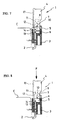
- Operation button 4 is pivotally connected to base button 3. Therefore, operation button 4 is mounted for pivotal movement between a raised position where it is in axial alignment with base button 3 (Fig. 3) and a folded position where it extends generally perpendicular to base button 3 (Fig. 1).
- Base button 3 is integrally connected with eject rod 2 for example by overmolding.
- Operation button 4 has a base portion 5 pivotally connected to base button 3 by a pivot pin 7 located within an elongated hole 10 formed through a support portion 9 of base button 3. Elongated hole 10 extends along the direction of insertion and ejection of the card.
- Base button 3 is also formed with a receptacle recess 6 for pivotally accommodating operation button 4.
- a marking 17 is provided on the side edge of operation button 4 for identifying the operation button in the raised position or in the folded position. While the marking 17 is provided on the side edge of operation button 4 to indicate the folded position in the shown embodiment, the marking could be provided on the front end of operation button 4 to indicate the raised position.
- the card eject button 1 of the card eject mechanism is normally in the folded position, i.e. whereat operation button 4 is perpendicular relative to base button 3, as shown in Fig. 5 and is maintained in this folded position unless and until ejection of the card is performed.
- the folded position the distance of projection of card eject button 1 from a front face of an electronic apparatus, such as a computer, is minimized to avoid inadvertent ejection of the card.
- a rounded end 11 of supporting portion 9 of base button 3 is held in contact with a flat surface 12 of operation button 4 to restrict pivotal movement of operation button 4 relative to base button 3.
- operation button 4 of eject button 1 is first pivoted in a direction indicated by arrow F in Fig. 5. At the same time, operation button 4 is laterally moved in the direction of arrow G in Fig. 6. Operation button 4 is then placed in axial alignment with base button 3 and thus in the raised position as shown in Fig. 7. In this position, a force P is applied to operation button 4 in the stroke or card insertion direction, as shown in Fig. 8, and pivot pin 7 moves axially within elongated hole 10. Base portion 5 of operation button 4 then engages receptacle recess 6 of base button 3. Thus, operation button 4 is therefore secured to base button 3 and fixed in the raised position. An eject rod accommodating recess 14 formed on one end of operation button 4 is aligned with and engages a corresponding end of eject rod 2 for fixing operation button 4 in the raised position.
- eject rod 2 and operation button 4 move in the card insertion direction to actuates the actuation lever and eject card C and move the card to the position shown by line E' in Fig. 9.
- the operation button may be further depressed until the card C is completely ejected as shown by line E''. At the eject position of E'', the card can be manually removed from the card-receiving connector. After completion of ejection, eject button 1 may be locked in the fully depressed position by a known lock mechanism.
- the card When card C is to be used, the card is inserted into a card slot in the card-receiving connector. At the end of the insertion stroke of the card, whereat the terminals of the card are electrically connected with the terminals of the header of the card-receiving connector, eject button 1 is released from its locking position to allow it to return to the perpendicular position shown in Fig. 5 through a process opposite to that described above with respect to the card ejecting operation.
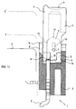
- Figs. 10 and 11 show a second embodiment of the card eject mechanism according to the present invention.
- the second embodiment of the invention differs from the above-described embodiment primarily due to the presence of an elastically deformable lock arm 8.
- the lock arm 8 is formed integrally with base button 3 and is designed for locking operation button 4 in its raised position and its folded position.
- operation button 4 is formed with a recess 16 which corresponds to a locking end 15 of the lock arm 8. Therefore, when locking end 15 engages recess 16 of operation button 4, operation button 4 is positively fixed in the folded position.
- locking end 15 of lock arm 8 contacts the side surface of the operation button 4 for restricting pivotal motion of operation button 4.
- the cantilevered construction of lock arm 8 may provide a "click" or tactile feedback sensation during pivoting of operation button 4 of eject button 1.
- marking 17 is located at the front end for indicating the raised position of operation button 4.
- the present invention simplifies the construction of the card eject mechanism. Furthermore, the simplified construction allows for miniaturization of the card eject mechanism and thus for miniaturizing the entire card-receiving connector.
- the operation button can be positively locked in either the raised position or the folded position.
- the lock arm may provide tactile feedback during pivoting the operation button relative to the base button, additional components such as springs which heretofore were used to provide tactile feedback, are unnecessary. Therefore, the number of parts required for the card eject mechanism is reduced to further simplify the structure.
Landscapes
- Physics & Mathematics (AREA)
- General Physics & Mathematics (AREA)
- Engineering & Computer Science (AREA)
- Theoretical Computer Science (AREA)
- Coupling Device And Connection With Printed Circuit (AREA)
- Details Of Connecting Devices For Male And Female Coupling (AREA)
Applications Claiming Priority (3)
| Application Number | Priority Date | Filing Date | Title |
|---|---|---|---|
| JP26843294 | 1994-10-06 | ||
| JP6268432A JP2707061B2 (ja) | 1994-10-06 | 1994-10-06 | カ−ドドライブ装置に於けるカ−ドイジェクト機構 |
| JP268432/94 | 1994-10-06 |
Publications (2)
| Publication Number | Publication Date |
|---|---|
| EP0706148A2 true EP0706148A2 (de) | 1996-04-10 |
| EP0706148A3 EP0706148A3 (de) | 1999-11-17 |
Family
ID=17458415
Family Applications (1)
| Application Number | Title | Priority Date | Filing Date |
|---|---|---|---|
| EP95115493A Withdrawn EP0706148A3 (de) | 1994-10-06 | 1995-09-30 | Vorrichtung zum Kartenauswerfen |
Country Status (6)
| Country | Link |
|---|---|
| US (1) | US5653603A (de) |
| EP (1) | EP0706148A3 (de) |
| JP (1) | JP2707061B2 (de) |
| KR (1) | KR0140327Y1 (de) |
| MY (1) | MY112544A (de) |
| SG (1) | SG38881A1 (de) |
Cited By (1)
| Publication number | Priority date | Publication date | Assignee | Title |
|---|---|---|---|---|
| EP1445728A1 (de) * | 2003-02-04 | 2004-08-11 | Molex Incorporated | IC Kartenverbinder |
Families Citing this family (14)
| Publication number | Priority date | Publication date | Assignee | Title |
|---|---|---|---|---|
| JP2757162B2 (ja) * | 1995-02-03 | 1998-05-25 | 日本航空電子工業株式会社 | 離脱機構付きコネクタ |
| JP3250659B2 (ja) * | 1997-03-24 | 2002-01-28 | タイコエレクトロニクスアンプ株式会社 | カードコネクタ |
| JP2887865B2 (ja) * | 1997-06-02 | 1999-05-10 | アルプス電気株式会社 | コネクタ装置 |
| TW390521U (en) * | 1997-06-05 | 2000-05-11 | Hon Hai Prec Ind Co Ltd | Electric connector |
| TW377909U (en) * | 1997-07-15 | 1999-12-21 | Hon Hai Prec Ind Co Ltd | Electronic card connector |
| JP2839242B1 (ja) * | 1997-09-19 | 1998-12-16 | アルプス電気株式会社 | Icカード用コネクタ装置 |
| US7014118B1 (en) * | 1997-10-10 | 2006-03-21 | Robinson Nugent, Inc | Module header apparatus |
| JPH11195451A (ja) * | 1997-12-26 | 1999-07-21 | Amp Japan Ltd | イジェクト用ボタン |
| TW379867U (en) * | 1997-12-27 | 2000-01-11 | Hon Hai Prec Ind Co Ltd | Card-backing mechanism for electronic card connector |
| JP3701792B2 (ja) * | 1998-04-10 | 2005-10-05 | アルプス電気株式会社 | コネクタ装置 |
| JP2000182714A (ja) * | 1998-12-18 | 2000-06-30 | Molex Inc | イジェクト機構及びそれを用いた媒体装着装置 |
| TW411048U (en) * | 1998-12-22 | 2000-11-01 | Hon Hai Prec Ind Co Ltd | Electronic card connector |
| TW474489U (en) * | 2001-02-27 | 2002-01-21 | Hon Hai Prec Ind Co Ltd | Card ejecting mechanism of electrical card connector |
| DE202008014604U1 (de) * | 2008-11-04 | 2010-04-08 | Coninvers Gmbh | Elektrischer Steckverbinder |
Citations (1)
| Publication number | Priority date | Publication date | Assignee | Title |
|---|---|---|---|---|
| US5443395A (en) | 1994-06-08 | 1995-08-22 | Molex Incorporated | Ejector system for an IC card connector apparatus |
Family Cites Families (4)
| Publication number | Priority date | Publication date | Assignee | Title |
|---|---|---|---|---|
| JP2659030B2 (ja) * | 1991-09-12 | 1997-09-30 | デュポン・シンガポール・ピーティーイー・リミテッド | コネクタ装置 |
| DE69117961T2 (de) * | 1991-12-16 | 1996-07-25 | Molex Inc | Auswurfsvorrichtung in einer Verbindervorrichtung für IC-Karten |
| US5211568A (en) * | 1992-02-24 | 1993-05-18 | Molex Incorporated | Edge card connector with latch/eject mechanism |
| US5507658A (en) * | 1994-10-05 | 1996-04-16 | Hon Hai Precision Ind. Co., Ltd. | Ejector mechanism for memory card connector with variably positionable pushing block means |
-
1994
- 1994-10-06 JP JP6268432A patent/JP2707061B2/ja not_active Expired - Fee Related
-
1995
- 1995-09-26 US US08/534,225 patent/US5653603A/en not_active Expired - Lifetime
- 1995-09-30 EP EP95115493A patent/EP0706148A3/de not_active Withdrawn
- 1995-10-05 SG SG1995001496A patent/SG38881A1/en unknown
- 1995-10-05 KR KR2019950027832U patent/KR0140327Y1/ko not_active Expired - Lifetime
- 1995-10-05 MY MYUI95002987A patent/MY112544A/en unknown
Patent Citations (1)
| Publication number | Priority date | Publication date | Assignee | Title |
|---|---|---|---|---|
| US5443395A (en) | 1994-06-08 | 1995-08-22 | Molex Incorporated | Ejector system for an IC card connector apparatus |
Cited By (1)
| Publication number | Priority date | Publication date | Assignee | Title |
|---|---|---|---|---|
| EP1445728A1 (de) * | 2003-02-04 | 2004-08-11 | Molex Incorporated | IC Kartenverbinder |
Also Published As
| Publication number | Publication date |
|---|---|
| JP2707061B2 (ja) | 1998-01-28 |
| MY112544A (en) | 2001-07-31 |
| KR960015503U (ko) | 1996-05-17 |
| EP0706148A3 (de) | 1999-11-17 |
| JPH08123916A (ja) | 1996-05-17 |
| KR0140327Y1 (ko) | 1999-04-15 |
| US5653603A (en) | 1997-08-05 |
| SG38881A1 (en) | 1997-04-17 |
Similar Documents
| Publication | Publication Date | Title |
|---|---|---|
| US5653603A (en) | Card eject mechanism for card-receiving connector | |
| JP2576064Y2 (ja) | コネクタ装置 | |
| US5275573A (en) | Electrical connector eject mechanism | |
| US5443395A (en) | Ejector system for an IC card connector apparatus | |
| US6609919B2 (en) | Card connector | |
| US6648694B2 (en) | Connector for memory card | |
| EP0720259A2 (de) | Steckverbinder für eine miniatur gedruckte Platte | |
| US6149450A (en) | Smart card adapter latch | |
| JP2002522874A (ja) | Icカードを保持するラッチを備えた電気コネクタ | |
| JP2839242B1 (ja) | Icカード用コネクタ装置 | |
| JP2001209771A (ja) | カード接続用アダプタおよびアンテナ付きicカード | |
| JPH08511115A (ja) | Simカード及び標準カード用のsmtリーダー | |
| US6839431B2 (en) | Card connector | |
| US6739911B2 (en) | Card connector unit provided with first accommodating position and second accommodating position | |
| JP2002289299A (ja) | カード用コネクタ装置 | |
| US5281157A (en) | Connector device for an information processing medium | |
| US6176714B1 (en) | Ejector for electrical card connector | |
| US6663408B2 (en) | Card connector | |
| US6325653B1 (en) | Terminal connecting apparatus for storage device | |
| US7179104B2 (en) | Connector which can be reduced in size | |
| JPH11176516A (ja) | 部材装着装置 | |
| JP3887164B2 (ja) | カード用コネクタ装置 | |
| JP3450995B2 (ja) | Icカード用コネクタ装置 | |
| JPH11250195A (ja) | スマートカードリーダ | |
| JP2513056Y2 (ja) | メモリカ―ド用コネクタ |
Legal Events
| Date | Code | Title | Description |
|---|---|---|---|
| PUAI | Public reference made under article 153(3) epc to a published international application that has entered the european phase |
Free format text: ORIGINAL CODE: 0009012 |
|
| AK | Designated contracting states |
Kind code of ref document: A2 Designated state(s): DE FR GB IT NL |
|
| PUAL | Search report despatched |
Free format text: ORIGINAL CODE: 0009013 |
|
| AK | Designated contracting states |
Kind code of ref document: A3 Designated state(s): DE FR GB IT NL |
|
| RIC1 | Information provided on ipc code assigned before grant |
Free format text: 6G 06K 13/08 A, 6H 01R 13/633 B |
|
| 17P | Request for examination filed |
Effective date: 20000505 |
|
| 17Q | First examination report despatched |
Effective date: 20020617 |
|
| STAA | Information on the status of an ep patent application or granted ep patent |
Free format text: STATUS: THE APPLICATION IS DEEMED TO BE WITHDRAWN |
|
| 18D | Application deemed to be withdrawn |
Effective date: 20021029 |