EP0705528B1 - Hochspannungsgenerator - Google Patents
Hochspannungsgenerator Download PDFInfo
- Publication number
- EP0705528B1 EP0705528B1 EP94920496A EP94920496A EP0705528B1 EP 0705528 B1 EP0705528 B1 EP 0705528B1 EP 94920496 A EP94920496 A EP 94920496A EP 94920496 A EP94920496 A EP 94920496A EP 0705528 B1 EP0705528 B1 EP 0705528B1
- Authority
- EP
- European Patent Office
- Prior art keywords
- circuit
- primary
- transformer
- voltage generator
- windings
- Prior art date
- Legal status (The legal status is an assumption and is not a legal conclusion. Google has not performed a legal analysis and makes no representation as to the accuracy of the status listed.)
- Expired - Lifetime
Links
Images

Classifications
-
- H—ELECTRICITY
- H05—ELECTRIC TECHNIQUES NOT OTHERWISE PROVIDED FOR
- H05B—ELECTRIC HEATING; ELECTRIC LIGHT SOURCES NOT OTHERWISE PROVIDED FOR; CIRCUIT ARRANGEMENTS FOR ELECTRIC LIGHT SOURCES, IN GENERAL
- H05B6/00—Heating by electric, magnetic or electromagnetic fields
- H05B6/64—Heating using microwaves
- H05B6/66—Circuits
- H05B6/666—Safety circuits
Definitions
- the present invention relates to a generator high voltage intended to supply at least a payload of the unidirectional type such that, for example, a magnetron or an electron tube and comprising a step-up transformer comprising a primary stage connected to a primary circuit, and a secondary stage having a winding connected to a secondary circuit comprising the load of use, said primary circuit being connected to an energy source electric and comprising electronic switching means so as to supply said transformer with high frequency current.
- the primary stage of the transformer comprises first and second windings, mounted in a serial link having an intermediate socket and two end sockets, the primary circuit being connected directly to the intermediate socket.
- the object of the present invention is the realization of a transformer of a reduced price, which is perfectly suited for use in a generator high voltage for microwave oven and susceptible mass production.
- the primary circuit is connected to one of the two end taps via said switching means, a capacity connecting the two end sockets so as to produce, with the first and second windings, an oscillating circuit.
- the generator uses a transformer series resonance whose operation is particularly suitable for a primary circuit comprising means switches consisting of IGBT type switches (Anglo-Saxon initials set for "Insulated Gate Bipolar Transistor ”) or MCT (Anglo-Saxon initials set for "Multiple Collector Transistor).
- IGBT type switches Anglo-Saxon initials set for "Insulated Gate Bipolar Transistor ”
- MCT Anglo-Saxon initials set for "Multiple Collector Transistor
- the high-voltage generator is intended for supplying one or possibly several loads of the unidirectional type such as, for example, a microwave oven magnetron or an electronic tube, and comprises a step-up transformer comprising, as we can see in Figure 1, a primary stage E 1 connected to a primary circuit CP and a secondary stage E 2 having a winding L 3 connected to a secondary circuit S 0 , S 1 comprising the load of use, said circuit primary CP connecting the primary stage E 1 of the transformer T to a source of electrical energy B 0 , B i and comprising switching means K so as to supply the transformer T with high frequency current.
- a step-up transformer comprising, as we can see in Figure 1, a primary stage E 1 connected to a primary circuit CP and a secondary stage E 2 having a winding L 3 connected to a secondary circuit S 0 , S 1 comprising the load of use, said circuit primary CP connecting the primary stage E 1 of the transformer T to a source of electrical energy B 0 , B i and comprising switching
- a series resonance transformer i.e. a transformer with self leakage inductance on a capacity, generally presents itself as an element of type inductive for low frequencies and resonant type when the frequency rises.
- Such an element results from the association of a perfect transformer TP, with a self-inductance L and a capacity C.
- the primary stage E 1 of the transformer T comprises a first and a second winding L 1 , L 2 , the primary circuit being connected on the one hand to the first winding L 1 and, on the other hand, by l intermediary of a capacity C, at the second winding L 2 , said second winding L 2 being mounted in series with the first winding L 1 at the terminals of the capacity C, so as to produce an oscillating circuit.
- a transformer having a primary winding provided with an intermediate socket PI and a socket at each end.
- the primary circuit connects an end socket and the intermediate socket PI to the energy source B 0 , B 1 and the two end sockets are connected together by the capacitor C.
- the inductances of the two windings L 1 and L 2 constituted respectively by the winding on either side of the intermediate tap, are in series in the oscillating circuit which includes the capacity C.
- the high frequency resonant transformer series incorporates the self L and the transformer TP on the same magnetic circuit and thanks to a particular geometrical arrangement of the windings on the magnetic circuit is carried out between the windings couplings adapted to the operation of the load of use likely to be powered.
- Such a transformer consists of three coil carcasses assembled and remains particularly expensive, especially in a mass production application.
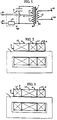
- FIGS. 2 and 3 which are embodiments of transformers according to the invention show a transformer T consisting of a ferrite 1, a carcass 2 comprising coils 3, 4 and 5 carrying the so-called primary windings L 1 and L 2 and a secondary winding L 3 .
- An arrangement of the windings L 1 and L 2 in an embodiment as shown schematically in Figure 2 results in a relatively weak coupling between the windings L 1 and L 2 .
- the two windings of the primary stage have a mutual coupling coefficient, or degree of coupling, between 0.5 and 0.7 and have values of substantially equal self-inductance. With such values of the coupling coefficient, we reach a coefficient effective coupling of the order of 0.9.
- the secondary circuit including a load of use can be realized according to several variants. Two particularly interesting versions for feeding a magnetron are illustrated in Figures 5 and 6.
- the secondary circuit comprises rectifying means.
- the use load U has two supply terminals M 1 , M 2 connected, on the one hand, to a first terminal N 1 of the secondary winding L 3 , respectively by two diodes D 1 and D 2 polarized so opposite to each other, and, on the other hand, to a second terminal N 2 of the secondary winding L 3 respectively by two capacitors C 1 and C 2 .
- the circuit comprises a magnetron M directly connected to the terminals of the secondary winding L 3 and a filtering capacity connected in parallel to the terminals of the magnetron.
- the capacitor Cf represented in FIG. 6 and which is connected in parallel to the magnetron M in fact represents the association of several capacitors, in particular of filtering capacitors and of capacitors internal to the magnetron.
Claims (7)
- Hochspannungsgenerator, der zur Versorgung wenigstens einer Nutzlast vom unidirektionalen Typ wie beispielsweise eines Magnetrons oder einer Elektronenröhre bestimmt ist und einen Aufwärtstransformator (T) mit einer mit einem Primärkreis (CP) verbundenen Primärstufe (E1) und einer Sekundärstufe (E2) aufweist, die eine Wicklung (L3) umfaßt, die mit einem Sekundärkreis (S0, S1) verbunden ist, der die Nutzlast aufweist, wobei der Primärkreis (CP) die Primärstufe (E1) des Transformators (T) mit einer elektrischen Energiequelle (B0, B1) verbindet und Umschaltmittel (K) aufweist, so daß der Transformator mit einem hochfrequenten Strom versorgt wird, wobei die Primärstufe (E1) des Transformators (T) eine erste und eine zweite Wicklung (L1, L2) aufweist, die in Reihe geschaltet sind und einen Zwischenabgriff (Pl) und zwei Endabgriffe aufweisen, wobei der Primärkreis (CP) direkt mit dem Zwischenabgriff verbunden ist, dadurch gekennzeichnet, daß der Primärkreis andererseits über die Umschaltmittel (K) mit einem der beiden Endabgriffe verbunden ist, und daß eine Kapazität (C) die beiden Endabgriffe derart verbindet, daß mit der ersten und der zweiten Wicklung ein Schwingkreis gebildet wird.
- Hochspannungsgenerator nach Anspruch 1,
dadurch gekennzeichnet, daß die beiden Wicklungen der Primärstufe einen Kopplungskoeffizienten zwischen 0,5 und 0,7 besitzen und im wesentlichen gleiche Selbstinduktionswerte aufweisen. - Hochspannungsgenerator nach Anspruch 1 oder 2,
dadurch gekennzeichnet, daß die beiden Wicklungen der Primärstufe und der Sekundärstufe auf einem einzigen Gestell hergestellt sind. - Hochspannungsgenerator nach einem der vorhergehenden Ansprüche,
dadurch gekennzeichnet, daß der Sekundärkreis außerdem Gleichrichtungsmittel aufweist. - Hochspannungsgenerator nach Anspruch 4,
dadurch gekennzeichnet, daß die Nutzlast (U) zwei Versorgungsanschlüsse (M1, M2) aufweist, die einerseits über zwei Gleichrichterdioden (D1, D2), die einander entgegengesetzt polarisiert sind, mit einem ersten Anschluß (N1) der Sekundärwicklung (L3) und andererseits über zwei Kapazitäten (C1, C2) mit einem zweiten Anschluß (N2) der Sekundärwicklung (L3) verbunden sind. - Hochspannungsgenerator nach einem der Ansprüche 1 bis 3,
dadurch gekennzeichnet, daß der Sekundärkreis eine Filterkapazität aufweist, die parallel zu den Anschlüssen eines Magnetrons angeschlossen ist. - Hochspannungsgenerator nach einem der vorhergehenden Ansprüche,
dadurch gekennzeichnet, daß die Umschaltmittel Umschalter vom Typ IGBT oder MCT sind.
Applications Claiming Priority (3)
| Application Number | Priority Date | Filing Date | Title |
|---|---|---|---|
| FR9307565 | 1993-06-22 | ||
| FR9307565A FR2707052B1 (de) | 1993-06-22 | 1993-06-22 | |
| PCT/FR1994/000748 WO1995001083A1 (fr) | 1993-06-22 | 1994-06-21 | Generateur de haute tension |
Publications (2)
| Publication Number | Publication Date |
|---|---|
| EP0705528A1 EP0705528A1 (de) | 1996-04-10 |
| EP0705528B1 true EP0705528B1 (de) | 1998-02-11 |
Family
ID=9448419
Family Applications (1)
| Application Number | Title | Priority Date | Filing Date |
|---|---|---|---|
| EP94920496A Expired - Lifetime EP0705528B1 (de) | 1993-06-22 | 1994-06-21 | Hochspannungsgenerator |
Country Status (4)
| Country | Link |
|---|---|
| EP (1) | EP0705528B1 (de) |
| DE (1) | DE69408535T2 (de) |
| FR (1) | FR2707052B1 (de) |
| WO (1) | WO1995001083A1 (de) |
Families Citing this family (1)
| Publication number | Priority date | Publication date | Assignee | Title |
|---|---|---|---|---|
| KR20020071126A (ko) * | 2001-03-03 | 2002-09-12 | 주식회사 테크노.티 | 인터넷상에서 전송된 영상을 입체로 볼 수 있도록 한 시스템 |
Family Cites Families (8)
| Publication number | Priority date | Publication date | Assignee | Title |
|---|---|---|---|---|
| FR2180442A1 (de) * | 1972-04-17 | 1973-11-30 | Tibbs Christopher | |
| JPS6049554A (ja) * | 1983-08-30 | 1985-03-18 | Mitsubishi Electric Corp | マイクロ波放電光源装置用電源装置 |
| JPS61259488A (ja) * | 1985-05-14 | 1986-11-17 | 松下電器産業株式会社 | 高周波加熱装置 |
| EP0280100B1 (de) * | 1987-02-10 | 1995-05-10 | Matsushita Electric Industrial Co., Ltd. | Hochfrequenz-Heizapparat |
| US4747034A (en) * | 1987-03-05 | 1988-05-24 | David V. Dickey | High efficiency battery adapter |
| JPH01313884A (ja) * | 1988-06-13 | 1989-12-19 | Sharp Corp | 高周波加熱装置 |
| US4882666A (en) * | 1989-03-23 | 1989-11-21 | North American Philips Corporation | High frequency high voltage power supply with controlled output power |
| JPH03295189A (ja) * | 1990-03-28 | 1991-12-26 | Sharp Corp | インバータ電子レンジの駆動回路 |
-
1993
- 1993-06-22 FR FR9307565A patent/FR2707052B1/fr not_active Expired - Lifetime
-
1994
- 1994-06-21 EP EP94920496A patent/EP0705528B1/de not_active Expired - Lifetime
- 1994-06-21 WO PCT/FR1994/000748 patent/WO1995001083A1/fr active IP Right Grant
- 1994-06-21 DE DE69408535T patent/DE69408535T2/de not_active Expired - Fee Related
Also Published As
| Publication number | Publication date |
|---|---|
| EP0705528A1 (de) | 1996-04-10 |
| DE69408535T2 (de) | 1998-07-30 |
| FR2707052B1 (de) | 1996-10-11 |
| FR2707052A1 (de) | 1994-12-30 |
| WO1995001083A1 (fr) | 1995-01-05 |
| DE69408535D1 (de) | 1998-03-19 |
Similar Documents
| Publication | Publication Date | Title |
|---|---|---|
| FR2839189A1 (fr) | Transformateur de faible encombrement | |
| EP0267822A1 (de) | Hochfrequenztransformator mit gedruckter Schaltungswicklung, insbesondere für sehr hohe Spannungsquelle | |
| FR2627644A1 (fr) | Convertisseur continu-continu, sans pertes de commutation, notamment pour alimentation continue haute frequence ou pour amplificateur a tube a ondes progressives | |
| EP0705528B1 (de) | Hochspannungsgenerator | |
| EP1929630B1 (de) | Strikte steuerung elektrischer stromumsetzer | |
| US3701055A (en) | Ka-band solid-state switching circuit | |
| FR2858911A1 (fr) | Circuit d'eclairage a lampe a decharge a detection de courant ou de tension | |
| EP1063870B1 (de) | Fortbildung von Zündübertragern für Entladungslampen in Kraftfahrzeugscheinwerfern | |
| RU2072623C1 (ru) | Умножитель частоты | |
| WO2020115402A1 (fr) | Dispositif d'induction electromagnetique | |
| FR3050069A1 (fr) | Composant magnetique, circuit electrique resonant, convertisseur electrique et systeme electrique | |
| FR3009885A3 (de) | ||
| FR2730108A1 (fr) | Dispositif de commutation d'un circuit de haute tension a transformateur d'impulsion | |
| FR2607618A1 (fr) | Transformateur de retour de spot perfectionne et dispositif de visualisation a tube a rayons cathodiques muni d'un tel transformateur | |
| WO2017140674A1 (fr) | Composant magnétique, circuit electrique resonant, convertisseur electrique et systeme electrique | |
| EP0645886B1 (de) | Hochenergiezündgenerator insbesondere für eine Gasturbine | |
| FR2858910A1 (fr) | Circuit d'eclairage a lampe a decharge a convertisseur continu-alternatif | |
| US20230343504A1 (en) | Improved performance of converter | |
| FR2565399A1 (fr) | Transformateur a fort couplage primaire-secondaire | |
| FR2730342A1 (fr) | Transformateur electrique, en particulier pour circuit d'alimentation a resonance, et circuit equipe d'un tel transformateur | |
| FR3112886A1 (fr) | Ensemble comprenant au moins une première et une deuxième inductance | |
| FR2688356A1 (fr) | Limiteur de courant par inductance serie a circuit magnetique muni d'une gaine supraconductrice. | |
| FR2858907A1 (fr) | Circuit d'eclairage a lampe a decharge | |
| EP0576356B1 (de) | Schaltung für Fehlerstromschutzschalter | |
| FR3105637A1 (fr) | Filtrage d'une charge dans une architecture electrique |
Legal Events
| Date | Code | Title | Description |
|---|---|---|---|
| PUAI | Public reference made under article 153(3) epc to a published international application that has entered the european phase |
Free format text: ORIGINAL CODE: 0009012 |
|
| 17P | Request for examination filed |
Effective date: 19951213 |
|
| AK | Designated contracting states |
Kind code of ref document: A1 Designated state(s): BE DE GB IT NL |
|
| 17Q | First examination report despatched |
Effective date: 19960530 |
|
| GRAG | Despatch of communication of intention to grant |
Free format text: ORIGINAL CODE: EPIDOS AGRA |
|
| GRAG | Despatch of communication of intention to grant |
Free format text: ORIGINAL CODE: EPIDOS AGRA |
|
| GRAH | Despatch of communication of intention to grant a patent |
Free format text: ORIGINAL CODE: EPIDOS IGRA |
|
| GRAH | Despatch of communication of intention to grant a patent |
Free format text: ORIGINAL CODE: EPIDOS IGRA |
|
| GRAA | (expected) grant |
Free format text: ORIGINAL CODE: 0009210 |
|
| AK | Designated contracting states |
Kind code of ref document: B1 Designated state(s): BE DE GB IT NL |
|
| ITF | It: translation for a ep patent filed |
Owner name: FUMERO BREVETTI S.N.C. |
|
| REF | Corresponds to: |
Ref document number: 69408535 Country of ref document: DE Date of ref document: 19980319 |
|
| GBT | Gb: translation of ep patent filed (gb section 77(6)(a)/1977) |
Effective date: 19980511 |
|
| PLBE | No opposition filed within time limit |
Free format text: ORIGINAL CODE: 0009261 |
|
| STAA | Information on the status of an ep patent application or granted ep patent |
Free format text: STATUS: NO OPPOSITION FILED WITHIN TIME LIMIT |
|
| 26N | No opposition filed | ||
| PGFP | Annual fee paid to national office [announced via postgrant information from national office to epo] |
Ref country code: GB Payment date: 20010618 Year of fee payment: 8 |
|
| PGFP | Annual fee paid to national office [announced via postgrant information from national office to epo] |
Ref country code: NL Payment date: 20010630 Year of fee payment: 8 |
|
| PGFP | Annual fee paid to national office [announced via postgrant information from national office to epo] |
Ref country code: BE Payment date: 20010816 Year of fee payment: 8 |
|
| REG | Reference to a national code |
Ref country code: GB Ref legal event code: IF02 |
|
| PG25 | Lapsed in a contracting state [announced via postgrant information from national office to epo] |
Ref country code: GB Free format text: LAPSE BECAUSE OF NON-PAYMENT OF DUE FEES Effective date: 20020621 |
|
| PGFP | Annual fee paid to national office [announced via postgrant information from national office to epo] |
Ref country code: DE Payment date: 20020625 Year of fee payment: 9 |
|
| PG25 | Lapsed in a contracting state [announced via postgrant information from national office to epo] |
Ref country code: BE Free format text: LAPSE BECAUSE OF NON-PAYMENT OF DUE FEES Effective date: 20020630 |
|
| BERE | Be: lapsed |
Owner name: S.A. *MOULINEX Effective date: 20020630 |
|
| PG25 | Lapsed in a contracting state [announced via postgrant information from national office to epo] |
Ref country code: NL Free format text: LAPSE BECAUSE OF NON-PAYMENT OF DUE FEES Effective date: 20030101 |
|
| GBPC | Gb: european patent ceased through non-payment of renewal fee |
Effective date: 20020621 |
|
| NLV4 | Nl: lapsed or anulled due to non-payment of the annual fee |
Effective date: 20030101 |
|
| PG25 | Lapsed in a contracting state [announced via postgrant information from national office to epo] |
Ref country code: DE Free format text: LAPSE BECAUSE OF NON-PAYMENT OF DUE FEES Effective date: 20040101 |
|
| PG25 | Lapsed in a contracting state [announced via postgrant information from national office to epo] |
Ref country code: IT Free format text: LAPSE BECAUSE OF NON-PAYMENT OF DUE FEES;WARNING: LAPSES OF ITALIAN PATENTS WITH EFFECTIVE DATE BEFORE 2007 MAY HAVE OCCURRED AT ANY TIME BEFORE 2007. THE CORRECT EFFECTIVE DATE MAY BE DIFFERENT FROM THE ONE RECORDED. Effective date: 20050621 |