EP0704622B1 - Saugventil-Mechanismus eines Kühlverdichters - Google Patents
Saugventil-Mechanismus eines Kühlverdichters Download PDFInfo
- Publication number
- EP0704622B1 EP0704622B1 EP95306198A EP95306198A EP0704622B1 EP 0704622 B1 EP0704622 B1 EP 0704622B1 EP 95306198 A EP95306198 A EP 95306198A EP 95306198 A EP95306198 A EP 95306198A EP 0704622 B1 EP0704622 B1 EP 0704622B1
- Authority
- EP
- European Patent Office
- Prior art keywords
- stopper
- compressor
- plate
- suction valve
- movement
- Prior art date
- Legal status (The legal status is an assumption and is not a legal conclusion. Google has not performed a legal analysis and makes no representation as to the accuracy of the status listed.)
- Expired - Lifetime
Links
Images


Classifications
-
- F—MECHANICAL ENGINEERING; LIGHTING; HEATING; WEAPONS; BLASTING
- F04—POSITIVE - DISPLACEMENT MACHINES FOR LIQUIDS; PUMPS FOR LIQUIDS OR ELASTIC FLUIDS
- F04B—POSITIVE-DISPLACEMENT MACHINES FOR LIQUIDS; PUMPS
- F04B49/00—Control, e.g. of pump delivery, or pump pressure of, or safety measures for, machines, pumps, or pumping installations, not otherwise provided for, or of interest apart from, groups F04B1/00 - F04B47/00
- F04B49/22—Control, e.g. of pump delivery, or pump pressure of, or safety measures for, machines, pumps, or pumping installations, not otherwise provided for, or of interest apart from, groups F04B1/00 - F04B47/00 by means of valves
- F04B49/225—Control, e.g. of pump delivery, or pump pressure of, or safety measures for, machines, pumps, or pumping installations, not otherwise provided for, or of interest apart from, groups F04B1/00 - F04B47/00 by means of valves with throttling valves or valves varying the pump inlet opening or the outlet opening
Definitions
- the present invention relates to a refrigerant compressor and, more particularly, to a valved suction mechanism of a refrigerant compressor capable of being used in an automotive air conditioning system.
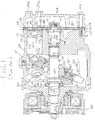
- Fig. 1 depicts a valved suction mechanism in a refrigerant compressor as described in U.S. Pat. No. 4,867,650 issued to Ikeda et al.
- a compressor 10 comprises a cylindrical housing assembly 120 including a cylinder block 121, a front end plate 123 at one end of cylinder block 121, and a rear end plate 124 at the other end of cylinder block 121.
- a crank chamber 122 is formed between cylinder block 121 and front end plate 123.
- Front end plate 123 is mounted on the front end of cylinder block 121 (toward the left side of Fig. 1) by a plurality of bolts 101.
- Rear end plate 124 is mounted on cylinder block 121 at its rear end (towards the right in Fig. 1) by a plurality of bolts 102.
- a valve plate 125 is located between rear end plate 124 and cylinder block 121.
- An opening 231 is centrally formed in front end plate 123 for supporting a drive shaft 126 by a bearing 130, which is disposed in opening 231.
- An inner end portion of drive shaft 126 is rotatably supported by a bearing 131 disposed within a center bore 210 formed in cylinder block 121. Bore 210 extends to a rearward end surface of cylinder block 121 wherein there is disposed a valve control mechanism 119.
- a cam rotor 140 is attached to drive shaft 126 by a pin member 261 and rotates together with shaft 126.
- a thrust needle bearing 132 is disposed between an inner end surface of front end plate 123 and an adjacent axial end surface of cam rotor 140.
- Cam rotor 140 has an arm 141 with a pin member 142 extending therefrom.
- a slant plate 150 is adjacent cam rotor 140 and has an opening 153 through which passes drive shaft 126.
- Slant plate 150 includes an arm 151 having a slot 152.
- Cam rotor 140 and slant plate 150 are coupled by pin member 142, which extends through slot 152 to create a hinged joint.
- Pin member 142 is slidable within slot 152 to allow adjustment of an angular position of slant plate 150 with respect to a longitudinal axis of drive shaft 126.
- a wobble plate 160 is nutatably mounted on slant plate 150 through bearings 161 and 162.
- a fork-shaped slider 163 is attached to an outer peripheral end of wobble plate 160 and is slidably mounted on a sliding rail 164, which is held between front end plate 123 and cylinder block 121.
- Fork-shaped slider 163 prevents rotation of wobble plate 160.
- Wobble plate 160 nutates along rail 164 as cam rotor 140 rotates with drive shaft 126.
- Cylinder block 121 includes a plurality of peripherally-located cylinders 170 in which a plurality of corresponding pistons 171 reciprocate. Each piston 171 is connected to wobble plate 160 by a connecting rod 172.
- Rear end plate 124 has a peripherally-located annular suction chamber 241 and a centrally-located discharge chamber 251.
- Valve plate 125 has a plurality of valved suction conduits 242 linking suction chamber 241 with the respective cylinders 170.
- Valve plate 125 also has a plurality of valved discharge conduits 252 linking discharge chamber 251 with the respective cylinders 170.
- Suction chamber 241 is connected to an evaporator (not shown) of a cooling circuit (not shown) by way of an inlet port 241a.
- Discharge chamber 251 is provided with outlet port 251a, which is connected to a condenser (not shown) of the cooling circuit (not shown).
- Gaskets 127 and 128 are respectively located between cylinder block 121 and an inner surface of valve plate 125, and an outer surface of valve plate 125 and rear end plate 124, to seal the mating surfaces of cylinder block 121, valve plate 125 and rear end plate 124.
- a disk-shaped adjusting screw member 133 is disposed in a central region of bore 210 between bearing 131 and valve control mechanism 119. Disk-shaped adjusting screw member 133 is screwed into bore 210 to be in contact with the inner end surface of drive shaft 126 through a washer 34, and adjusts an axial position of drive shaft 126 by tightening or loosing thereof.
- Connecting rod 172 has first and second ball portions 173a and 173b respectively formed at the front and rear ends thereof. Piston 171 is connected to second ball portion 173b.
- a discharge valve assembly includes a discharge reed valve 181 and a valve retainer 180 which are secured together to valve plate 125 by a fixing bolt 100.
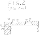
- Gasket 127 includes suction valve 191, formed therein, which opens and closes the suction conduits 242,
- a groove 190 is formed on a periphery of each cylinder 170 at the rearward and radially outer-most location thereof. Groove 190 restricts the opening motion of suction valve 191 by engaging a tip portion of suction valve 191.
- suction valve 191 produces an undesirable ripple noise.
- the aperture between suction valve 191 and suction hole 242 should be designed to be relatively shallow. Accordingly, a depth D (Fig. 2) of groove 190 should be designed be small. Moreover, this has the effect of reducing starting torque shock of the compressor when the compressor starts by operation of clutch 300.
- a disadvantage of this design is that if the depth of groove 190 is designed to be small, in order to reduce apple noise and starting torque shock of the compressor, the discharge ability of the compressor is reduced since the pressure loss of the refrigerant gas increases. Consequently, volumetric efficiency decreases. In this situation, it becomes necessary to increase the compressor size in order to increase volumetric efficiency. Therefore, it is difficult to simultaneously resolve each of the above-mentioned problems.
- US-A-4330999 discloses a suction valve assembly with variable control of the valve members contained therein.
- a suction valve assembly in combination with a compressor having a suction chamber and a discharge chamber on one side of a valve plate and a compression chamber on the other side of the valve plate, the assembly comprising:
- Fig. 1 is a longitudinal sectional view of a slant plate compressor in accordance with the prior art.
- Fig. 2 is an enlarged sectional view of a suction valve assembly in accordance with the prior art.
- Fig. 3 is a longitudinal sectional view of a slant plate compressor in accordance with an embodiment of the present invention.
- Fig. 4 is an enlarged sectional view of a suction valve assembly in accordance with an embodiment of the present invention.
- Fig. 5 is a cross-sectional view of the compressor of Fig. 3 taken along line 5-5 of showing the suction valve assembly of Fig. 4.
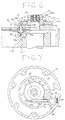
- Fig. 6 is an enlarged sectional view of a suction valve assembly in accordance with an embodiment of the present invention.
- Fig. 7 is cross-sectional view of the compressor of Fig. 3. taken along line 5-5 showing the suction valve assembly of Fig. 6.
- Fig. 8 is a partial axial view of a suction valve assembly in accordance with an embodiment of the present invention.
- Fig. 9 is a partial axial view of a suction valve assembly in accordance with an embodiment of the present invention.
- Fig. 10 is an enlarged partial sectional view of a suction valve assembly in accordance with an embodiment of the present invention and taken along line 10-10 of Fig. 9.
- Fig. 11 is an enlarged sectional view of a suction valve assembly in accordance with an embodiment of the present invention.
- Fig. 12 is an enlarged sectional view of a suction valve assembly in accordance with an embodiment of the present invention.
- Fig. 13 is a cross-sectional view of the compressor of Fig. 3 taken along line 5-5 and showing the section valve assembly of Fig. 12.
- Fig. 3 illustrates a fluid displacement apparatus in accordance with the present invention and, in particular, a slant plate compressor according to one embodiment of the present invention. Certain features of compressor 11 are similar to those described above in connection with the compressor depicted in Fig. 1. Therefore, a detailed description of the similar compressor features is omitted.
- a suction valve mechanism 30 comprises a base plate 43 in contact with a first side surface of a valve plate 35, a supporting plate 44, and a control plate 34 slidably sandwiched between base plate 43 and supporting plate 44.
- Base plate 43, control plate 34 and supporting plate 44 have openings 43a, 34a and 44a respectively formed at a central portion thereof, and are secured with together by a coupling device, such as nut 80, so that axial movement of base plate 43, control plate 34 and supporting plate 44 is restricted.
- base plate 43 has a plurality of holes 43b, which preferably correspond to a number of cylinders 170 of compressor 11, and which are preferably formed at equal intervals around opening 43a.
- Base plate 43 also has a plurality of grooves 43c formed to be in fluid communication with holes 43b. Grooves 43c are each provided with an O-ring 60.
- control plate 34 has a notch portion 46 formed on a first end surface thereof and at least partially surrounding opening 34a.
- Control plate 34 also has a plurality of channels 33 preferably corresponding to a number of cylinders 170.
- channels 33 have an arc-shaped axial cross section and are equally spaced about a periphery of control plate 34.
- a radial cross-section of channel 33 of notch portion 46 includes first stage portion 33a having depth D, which is formed to be linear and parallel to the first end surface of control plate 34.
- Channel 33 also has a second stage portion 33b formed to be linear, and which comprises a portion of the first end surface of control plate 34.
- Channel 33 also has inclined portion 33c formed to join first stage portion 33a and second stage portion 33b and, therefore being inclined with respect to the first end surface of control plate 34.
- Control plate 34 further includes cavity 46a formed therein and opening to the surface of notch portion 46.
- Base plate 43 has a similar cavity 43d formed on a surface thereof and opening toward notch portion 46.
- Ring spring 45 has first end portion 45a extending in an axial direction and second end portion 45b extending in an opposite axial direction and is disposed within notched portion so that first end portion 45a and second end portion 45b are respectively inserted into cavity 46a of control plate 46 and cavity 43d of base plate 43.
- cylinder block 121 includes a plurality of recessed portions 50 formed near each of cylinders 170.
- recessed portions 50 are formed radially inward of, and adjacent to, cylinders 170.
- Each recessed portion 50 includes a first cylindrical portion 50a opening to an end surface of cylinder block 121, a second cylindrical portion 50b extending from first cylindrical portion 50a toward crank chamber 122, and a semicylindrical portion 50c communicating cylinder 170 and first cylindrical portion 50a.
- Second cylindrical portion 50b preferably has a smaller diameter than first cylindrical portion 50a.
- suction valve mechanism 30 also comprises a stopper 31 disposed between cylinder block 121 and suction chamber 23, and extending through a hole formed in valve plate 35.
- Stopper 31 includes end portion 31b, a cylindrical portion 31c, and a flange portion 31a located at an end of cylindrical portion 31c opposite end portion 31b.
- Flange portion 3 la is capable of fittingly contacting an edge of suction valve member 26.
- stopper 31 In a rest state, stopper 31 is urged toward the direction of suction chamber 23 by a restoring force of a first coil spring 32, which is disposed at least partly within second cylindrical portion 50b of recessed portion 50.
- first coil spring 32 extends completely to a bottom portion 50c of recessed portion 50. The bias of stopper 31 and the contact of flange portion 31a with suction valve member 26 thus tends to close suction valve 26.
- control plate 34 also has a pin portion 37 axially extending from a second end surface thereof.
- Rear end plate 13 is provided with piston mechanism 135 therein.
- Piston mechanism 135 includes a cylinder 39 arranged to be substantially perpendicular to the axis of drive shaft 126, a piston 38 disposed within cylinder 39, a rod 36 extending from piston 38 toward suction chamber 23 and engageable with pin portion 37.
- Piston 38 is preferably capable of reciprocating within cylinder 39.
- a first end of cylinder 39 is closed by a faucet 40.
- a second coil spring 41 is disposed between a second end of cylinder 39 and piston 38 so as to urge piston 38 toward faucet 40.
- Cylinder 39 is communicated with discharge chamber 24 through passage 42 formed therebetween in rear end plate 13.
- drive shaft 126 is rotated by the engine of the vehicle through electromagnetic clutch 300.
- Cam rotor 140 rotates together with drive shaft 126, thereby rotating slant plate 150, which causes wobble plate 160 to nutate.
- the nutational motion of wobble plate 160 reciprocates pistons 171 in their respective cylinders 170.
- a refrigerant gas is introduced into suction chamber 23 through inlet port 23a.
- the gas then passes to cylinders 170 through suction valve mechanism 30 where it is compressed.
- the compressed refrigerant gas is discharged to discharge chamber 24 from each cylinder 170 through discharge conduits 27, and therefrom into the cooling circuit (not shown) through outlet port 24a.
- suction valve mechanism 30 When stopper 31 is at the position as shown in Fig. 4, flange portion 31a is at an axially shallow position within recessed portion 50. In this state, suction valve member 26 can only open to a minimum opening level.
- the pressure in cylinder 39 increases due to an increase of the pressure within discharge chamber 24. Thus, a difference is created between the pressure in cylinder 39 and the pressure in suction chamber 23. Accordingly, piston 38 moves toward suction chamber 23 against the restoring force of second coil spring 41.
- End portion 36a of position rod 36 protrudes from cylinder 39 and engages pin portion 37 to rotate control plate 34 in an amount equal to angle ⁇ against the restoring force of ring spring 45.
- control plate 34 The rotational movement of control plate 34 is depicted by arrow A shown in Fig. 10.
- stopper 31 As channel 33 consequently moves with control plate 34, stopper 31 is pushed downward by inclined portion 33c, against the restoring force of first coil spring 32.
- Flange portion 31a thereby moves to an axially deep position within recessed portion 50.
- suction valve member 26 can open to a maximum opening level. This is shown, for example, in Fig. 6.
- the pressure of discharge chamber 24 is relatively low at the time of starting the compressor.
- the position of flange portion 31a stopper 31 is at the shallow level.
- the pressure loss of refrigerant gas through suction hole 25 increases since the opening level of suction valve member 26 is at a minimum level.
- the volumetric efficiency of compressor 11 decreases.
- volumetric efficiency is gradually increased by the ratio of theoretical piston displacement volume to practical displacement. Therefore, the compressor need not conduct rapid compression work during starting and compressed gas is gradually discharged to discharge chamber 24 from cylinder 170. As a result, torque shock of the compressor during starting can be reduced.
- flange portion 31a When the pressure in discharge chamber 24 is low, as in a low-load situation, flange portion 31a is at the shallow position. Suction valve member 26 is restricted by flange portion 31a, such that movement of an end portion of suction valve memoer 26 is limited. This reduces ripple noise in suction valve member 26. Further, as the pressure in discharge chamber 24 gradually increases, as flange portion 31a moves to the deep position, the pressure loss of refrigerant gas through suction conduit 25 decreases since the opening level of suction valve member 26 is at a maximum level Thus, the volumetric efficiency of compressor 11 increases. Therefore, compressor 11 can obtain a high volumetric efficiency during high load operation. This advantage allows for a more compact compressor due to higher discharge ability of compressor 11 as compared to the discharge ability of prior art compressors of the same size. This higher discharge ability is obtained while simultaneously reducing vibrational valve noise and starting torque shock.
- Suction valve mechanism 61 comprises base plate 70 in contact with a first side surface of valve plate 35, and piston mechanism 72 axially disposed in a central portion of rear end plate 14.
- Base plate 70 includes threading hole 70a formed at a central portion thereof. Cylindrical member 194 is threaded into hole 70a.
- Base plate 70 also comprises a plurality of holes 70b, preferably corresponding to a number of cylinders 170, and preferably formed at equal intervals around threading hole 70a.
- Base plate 70 further comprises a plurality of grooves 70c formed to be in fluid communication with holes 70b. Grooves 70c are provided with O-rings 60.
- suction valve mechanism 61 includes a plurality of pin members 71, each having a cylindrical portion 71a and flange portion 71b formed at an end thereof.
- Piston mechanism 72 includes cylinder 74 formed in rear end plate 14 and being substantially coaxial with drive shaft 126. Piston mechanism 72 also includes piston 73 disposed within cylinder 74 and connected to a first end of a piston rod 79, and control plate 76 connected to a second end of piston rod 79, which is toward cylinder block 121. A first end of cylinder 74 is closed by faucet 77.
- First coil spring 75 is disposed between a second end of cylinder 74 and piston 73. Cylinder 74 is in fluid communication with annular discharge chamber 24 through passage 78 formed therebetween in rear end plate 14.
- Control plate 76 includes a plurality of openings 76a formed therein, which are preferably located at equal intervals around the center of control plate 76. Further, the plurality of pin members 71 extend respectively through openings 76a of control plate 76 and are connected to base plate 70 so that control plate 76 can move axially, while limited in movement by flange portions 71b and base plate 70.
Landscapes
- Engineering & Computer Science (AREA)
- Mechanical Engineering (AREA)
- General Engineering & Computer Science (AREA)
- Compressors, Vaccum Pumps And Other Relevant Systems (AREA)
- Compressor (AREA)
Claims (8)
- Ansaugventilanordnung (30, 61) in Kombination mit einem Kompressor (11), mit einer Ansaugkammer (23) und einer Ausgabekammer (24) auf einer Seite einer Ventilplatte (125) und einer Kompressionskammer auf der anderen Seite der Ventilplatte, wobei die Anordnung aufweist:dadurch gekennzeichnet, daßeinen Stopper (31), der in einem Durchgang (43b) vorgesehen ist, der die Ansaugkammer und die Kompressionskammer verbindet, wobei der Durchgang eine Leitung enthält, die sich durch die Ventilplatte erstreckt, wobei der Stopper zwischen einer ersten Position und einer zweiten Position bewegbar ist; undein Ventilteil (26), das an einem Ende der Leitung positioniert ist, das sich zu der Kompressionskammer öffnet, wobei das Ventilteil in Kontakt mit dem Stopper;der Stopper auf eine Änderung in einem Ausgabekammerdruck zum Bewegen zwischen der ersten und der zweiten Position reagiert,die Bewegung des Stoppers zur der ersten Position die Bewegung des Ventilteiles zu einer minimalen Öffnungsposition erlaubt, an der die Leitung an einem minimalen Betrag geöffnet ist,und die Bewegung des Stoppers zu der zweiten Position die Bewegung des Ventilteiles zu einer maximalen Öffnungsposition verursacht, an der die Leitung an einem maximalen Betrag geöffnet ist.
- Ansaugventilanordnung (30, 61) in Kombination mit einem Kompressor (11) nach Anspruch 1, bei der der Stopper (31) zu der ersten Position durch eine Feder (32) vorgespannt ist.
- Ansaugventilanordnung (30, 61) in Kombination mit einem Kompressor (11) nach Anspruch 1, bei der sich der Stopper (31) zu der zweiten Position als Reaktion auf eine Zunahme des Ausgabekammerdruckes bewegt.
- Ansaugventilanordnung (30, 61) in Kombination mit einem Kompressor (11) nach Anspruch 1, weiter mit
einer Druckdifferentialreaktionsvorrichtung (135, 72), die in einem Raum vorgesehen ist, wobei der Raum mit der Ausgabekammer (24) in Verbindung steht, wobei die Druckdifferentialreaktionsvorrichtung mit dem Stopper zum Bewegen des Stoppers zu der zweiten Position als Reaktion auf eine Zunahme des Ausgabekammerdruckes verbunden ist. - Ansaugventilanordnung (30, 61) in Kombination mit einem Kompressor (11) nach Anspruch 4, weiter miteinem Steuerteil (78) zum Verbinden der Druckdifferentialreaktionsvorrichtung (135, 72) mit dem Stopper (31),wobei die Druckdifferentialreaktionsvorrichtung in Eingriff mit dem Steuerteil zum Bewegen des Steuerteiles in eine erste Richtung als Reaktion auf eine Abnahme des Ausgabedruckes und in eine zweite Richtung als Reaktion auf eine Zunahme des Ausgabekammerdruckes in Eingriff bringbar ist,worin die Bewegung des Steuerteiles in die erste Richtung die Bewegung des Stoppers zu der ersten Position bewirkt und worin die Bewegung des Steuerteiles in die zweite Richtung die Bewegung des Stoppers zu der zweiten Position bewirkt.
- Ansaugventilanordnung (30, 61) in Kombination mit einem Kompressor (11) nach Anspruch 5, bei der, wenn sich das Steuerteil (78) zwischen der ersten Richtung und der zweiten Richtung bewegt, das Steuerteil sich innerhalb einer Ebene und um eine Achse hin- und herbewegt, die sich senkrecht zu der Ebene erstreckt.
- Ansaugventilanordnung (30) in Kombination mit einem Kompressor (11) nach Anspruch 5, bei der das Steuerteil ein Plattenteil (34) ist, das drehbar um eine Längsachse des Kompressors bewegbar ist und einen Kanal (33) aufweist, der in einer Oberfläche davon gebildet ist, zum gleitenden Kontaktieren mit dem zweiten Ende des Stoppers zum Bewegen des Stoppers.
- Ansaugventilanordnung (30) in Kombination mit einem Kompressor (11) nach Anspruch 7,worin der Kanal einen schrägen Abschnitt (33c) aufweist, der sich von einem ersten Niveau an der Oberfläche des Plattenteiles zu einem zweiten Niveau in einem axialen Abstand von dem ersten Niveau erstreckt,worin die Bewegung des Plattenteiles (34) in einer ersten Richtung bewirkt, daß sich das erste Niveau des schrägen Abschnittes dem zweiten Ende des Stoppers zum Bewegen des Stoppers zu der maximalen Öffnungsposition nähert,und worin die Bewegung des Plattenteiles in einer zweiten Richtung entgegengesetzt zu der ersten Richtung bewirkt, daß sich das zweite Niveau des schrägen Abschnittes dem zweiten Ende des Stoppers zum Ermöglichen, daß sich der Stopper zu der minimalen Öffnungsposition bewegt, nähert.
Applications Claiming Priority (3)
| Application Number | Priority Date | Filing Date | Title |
|---|---|---|---|
| JP23856894A JP3505233B2 (ja) | 1994-09-06 | 1994-09-06 | 圧縮機 |
| JP23856894 | 1994-09-06 | ||
| JP238568/94 | 1994-09-06 |
Publications (3)
| Publication Number | Publication Date |
|---|---|
| EP0704622A2 EP0704622A2 (de) | 1996-04-03 |
| EP0704622A3 EP0704622A3 (de) | 1997-01-02 |
| EP0704622B1 true EP0704622B1 (de) | 2001-03-14 |
Family
ID=17032162
Family Applications (1)
| Application Number | Title | Priority Date | Filing Date |
|---|---|---|---|
| EP95306198A Expired - Lifetime EP0704622B1 (de) | 1994-09-06 | 1995-09-05 | Saugventil-Mechanismus eines Kühlverdichters |
Country Status (4)
| Country | Link |
|---|---|
| US (1) | US5688111A (de) |
| EP (1) | EP0704622B1 (de) |
| JP (1) | JP3505233B2 (de) |
| DE (1) | DE69520318T2 (de) |
Families Citing this family (15)
| Publication number | Priority date | Publication date | Assignee | Title |
|---|---|---|---|---|
| JPH09166075A (ja) * | 1995-12-13 | 1997-06-24 | Sanden Corp | ピストン往復動式圧縮機 |
| JP3561366B2 (ja) * | 1996-03-29 | 2004-09-02 | サンデン株式会社 | 強制リデュース装置及びそれを備えた圧縮機 |
| DE19634519A1 (de) * | 1996-08-27 | 1998-03-05 | Leybold Vakuum Gmbh | Kolbenvakuumpumpe mit Eintritt und Austritt |
| US6206652B1 (en) | 1998-08-25 | 2001-03-27 | Copeland Corporation | Compressor capacity modulation |
| JP4034883B2 (ja) | 1998-07-08 | 2008-01-16 | サンデン株式会社 | 温度自動膨張弁 |
| JP2000016068A (ja) * | 1998-07-08 | 2000-01-18 | Sanden Corp | 温度自動膨張弁 |
| JP2001193647A (ja) * | 2000-01-17 | 2001-07-17 | Sanden Corp | 往復動型圧縮機 |
| DE10034238A1 (de) * | 2000-07-13 | 2002-01-31 | Mannesmann Rexroth Ag | Hydrotransformator |
| DE102005007849A1 (de) * | 2005-01-25 | 2006-08-17 | Valeco Compressor Europe Gmbh | Axialkolbenverdichter |
| DE102005038273A1 (de) * | 2005-08-02 | 2007-02-08 | Linde Ag | Maschine mit einem drehbaren Rotor |
| BRPI0505734A (pt) * | 2005-12-19 | 2007-09-25 | Brasil Compressores Sa | arranjo de montagem de válvula para compressor de refrigeração |
| US8157538B2 (en) | 2007-07-23 | 2012-04-17 | Emerson Climate Technologies, Inc. | Capacity modulation system for compressor and method |
| DE102008052744B3 (de) * | 2008-10-22 | 2010-04-01 | Voith Patent Gmbh | Kompressor |
| EP2391826B1 (de) | 2009-01-27 | 2017-03-15 | Emerson Climate Technologies, Inc. | Entladesystem und verfahren für kompressoren |
| JP7201311B2 (ja) * | 2017-07-19 | 2023-01-10 | 株式会社日立産機システム | 圧縮機 |
Family Cites Families (14)
| Publication number | Priority date | Publication date | Assignee | Title |
|---|---|---|---|---|
| US2544821A (en) * | 1945-09-07 | 1951-03-13 | Joy Mfg Co | Compressor supercharging system |
| US2585168A (en) * | 1947-08-21 | 1952-02-12 | Worthington Pump & Mach Corp | Compressor control circuit |
| US3043496A (en) * | 1958-11-12 | 1962-07-10 | Westinghouse Air Brake Co | Means and method of inhibiting the rise of the temperature of compressor cylinder incidental to operation while unloaded |
| US3073510A (en) * | 1960-12-29 | 1963-01-15 | Trane Co | Compressor unloading mechanism |
| DE2357578A1 (de) * | 1973-11-19 | 1975-05-22 | Billstein Spezialfab Wilhelm | Regelbare zungenventileinrichtung fuer kolbenverdichter |
| DD110919A1 (de) * | 1974-03-15 | 1975-01-12 | ||
| US4330999A (en) * | 1977-07-27 | 1982-05-25 | Kabushiki Kaisha Toyoda Jidoshokki Seisakusho | Refrigerant compressor |
| US4519752A (en) * | 1982-09-03 | 1985-05-28 | Applied Power Inc. | Control system for a variable displacement pump |
| JPS59113279A (ja) * | 1982-12-20 | 1984-06-29 | Toyoda Autom Loom Works Ltd | 可変容量冷媒圧縮機 |
| US4588359A (en) * | 1984-12-24 | 1986-05-13 | Vilter Manufacturing Corporation | Compressor capacity control apparatus |
| JPS6282282A (ja) * | 1985-10-02 | 1987-04-15 | Toyoda Autom Loom Works Ltd | 可変容量圧縮機 |
| JPH0756258B2 (ja) * | 1985-10-04 | 1995-06-14 | 株式会社豊田自動織機製作所 | 可変容量圧縮機 |
| JPH0450470Y2 (de) * | 1987-04-16 | 1992-11-27 | ||
| JPH0599136A (ja) * | 1991-10-23 | 1993-04-20 | Sanden Corp | 可変容量型斜板式圧縮機 |
-
1994
- 1994-09-06 JP JP23856894A patent/JP3505233B2/ja not_active Expired - Fee Related
-
1995
- 1995-09-05 DE DE69520318T patent/DE69520318T2/de not_active Expired - Fee Related
- 1995-09-05 EP EP95306198A patent/EP0704622B1/de not_active Expired - Lifetime
- 1995-09-06 US US08/523,921 patent/US5688111A/en not_active Expired - Lifetime
Also Published As
| Publication number | Publication date |
|---|---|
| JP3505233B2 (ja) | 2004-03-08 |
| JPH0874734A (ja) | 1996-03-19 |
| DE69520318T2 (de) | 2001-09-06 |
| DE69520318D1 (de) | 2001-04-19 |
| US5688111A (en) | 1997-11-18 |
| EP0704622A3 (de) | 1997-01-02 |
| EP0704622A2 (de) | 1996-04-03 |
Similar Documents
| Publication | Publication Date | Title |
|---|---|---|
| EP0172970B1 (de) | Kältemittelverdichter | |
| EP0704622B1 (de) | Saugventil-Mechanismus eines Kühlverdichters | |
| US4632640A (en) | Wobble plate type compressor with a capacity adjusting mechanism | |
| US5137431A (en) | Lubricating mechanism and method for a piston assembly of a slant plate type compressor | |
| US4664604A (en) | Slant plate type compressor with capacity adjusting mechanism and rotating swash plate | |
| EP0698735B1 (de) | Führungsmechanismus für Verdrängerkolben eines Kolbenverdichters | |
| EP0340024B1 (de) | Schiefscheibenverdichter mit variablem Hubmechanismus | |
| EP0809025A1 (de) | Verdrängerkolben eines Kolbenverdichters | |
| EP0869281B1 (de) | Fluidverdrängungsanlage mit Einrichtung zu veränderlicher Verdrängung | |
| US6592337B2 (en) | Shaft seal of a lip type with fluid guiding components having the same | |
| EP1394411B1 (de) | Taumelscheibenkompressor mit variabler Verdrängung | |
| EP0809024B1 (de) | Verdrängerkolben eines Kolbenverdichters | |
| US5292233A (en) | Variable capacity swash plate type compressor | |
| US5772406A (en) | Piston-type compressor with a lubricating system | |
| US5255569A (en) | Slant plate type compressor with variable displacement mechanism | |
| EP0499341B1 (de) | Taumelscheibenkompressor | |
| EP0844389B1 (de) | Schrägscheibenverdichter | |
| US5873706A (en) | Valved suction mechanism for refrigerant compressor | |
| CA2221475C (en) | Variable displacement compressor | |
| US6224349B1 (en) | Reciprocating type compressor having orbiting valve plate | |
| CA2210265C (en) | Piston for compressors | |
| US5299918A (en) | Bearing for compressor drive shaft | |
| US20050180860A1 (en) | Compressor having swash plate assembly | |
| JP3186322B2 (ja) | 片側ピストン式可変容量圧縮機における潤滑構造 | |
| EP1283360A2 (de) | Kanalstruktur für Verdichter variabler Verdrängung |
Legal Events
| Date | Code | Title | Description |
|---|---|---|---|
| PUAI | Public reference made under article 153(3) epc to a published international application that has entered the european phase |
Free format text: ORIGINAL CODE: 0009012 |
|
| AK | Designated contracting states |
Kind code of ref document: A2 Designated state(s): DE FR GB IT SE |
|
| K1C1 | Correction of patent application (title page) published |
Effective date: 19960403 |
|
| PUAL | Search report despatched |
Free format text: ORIGINAL CODE: 0009013 |
|
| AK | Designated contracting states |
Kind code of ref document: A3 Designated state(s): DE FR GB IT SE |
|
| 17P | Request for examination filed |
Effective date: 19970620 |
|
| 17Q | First examination report despatched |
Effective date: 19991015 |
|
| GRAG | Despatch of communication of intention to grant |
Free format text: ORIGINAL CODE: EPIDOS AGRA |
|
| GRAG | Despatch of communication of intention to grant |
Free format text: ORIGINAL CODE: EPIDOS AGRA |
|
| GRAH | Despatch of communication of intention to grant a patent |
Free format text: ORIGINAL CODE: EPIDOS IGRA |
|
| GRAH | Despatch of communication of intention to grant a patent |
Free format text: ORIGINAL CODE: EPIDOS IGRA |
|
| GRAA | (expected) grant |
Free format text: ORIGINAL CODE: 0009210 |
|
| AK | Designated contracting states |
Kind code of ref document: B1 Designated state(s): DE FR GB IT SE |
|
| ET | Fr: translation filed | ||
| REF | Corresponds to: |
Ref document number: 69520318 Country of ref document: DE Date of ref document: 20010419 |
|
| ITF | It: translation for a ep patent filed |
Owner name: JACOBACCI & PERANI S.P.A. |
|
| PGFP | Annual fee paid to national office [announced via postgrant information from national office to epo] |
Ref country code: DE Payment date: 20010828 Year of fee payment: 7 |
|
| PGFP | Annual fee paid to national office [announced via postgrant information from national office to epo] |
Ref country code: GB Payment date: 20010905 Year of fee payment: 7 |
|
| PGFP | Annual fee paid to national office [announced via postgrant information from national office to epo] |
Ref country code: SE Payment date: 20010906 Year of fee payment: 7 |
|
| PGFP | Annual fee paid to national office [announced via postgrant information from national office to epo] |
Ref country code: FR Payment date: 20010911 Year of fee payment: 7 |
|
| REG | Reference to a national code |
Ref country code: GB Ref legal event code: IF02 |
|
| PLBE | No opposition filed within time limit |
Free format text: ORIGINAL CODE: 0009261 |
|
| STAA | Information on the status of an ep patent application or granted ep patent |
Free format text: STATUS: NO OPPOSITION FILED WITHIN TIME LIMIT |
|
| 26N | No opposition filed | ||
| PG25 | Lapsed in a contracting state [announced via postgrant information from national office to epo] |
Ref country code: GB Free format text: LAPSE BECAUSE OF NON-PAYMENT OF DUE FEES Effective date: 20020905 |
|
| PG25 | Lapsed in a contracting state [announced via postgrant information from national office to epo] |
Ref country code: SE Free format text: LAPSE BECAUSE OF NON-PAYMENT OF DUE FEES Effective date: 20020906 |
|
| PG25 | Lapsed in a contracting state [announced via postgrant information from national office to epo] |
Ref country code: DE Free format text: LAPSE BECAUSE OF NON-PAYMENT OF DUE FEES Effective date: 20030401 |
|
| GBPC | Gb: european patent ceased through non-payment of renewal fee |
Effective date: 20020905 |
|
| EUG | Se: european patent has lapsed | ||
| PG25 | Lapsed in a contracting state [announced via postgrant information from national office to epo] |
Ref country code: FR Free format text: LAPSE BECAUSE OF NON-PAYMENT OF DUE FEES Effective date: 20030603 |
|
| REG | Reference to a national code |
Ref country code: FR Ref legal event code: ST |
|
| PG25 | Lapsed in a contracting state [announced via postgrant information from national office to epo] |
Ref country code: IT Free format text: LAPSE BECAUSE OF NON-PAYMENT OF DUE FEES Effective date: 20050905 |