EP0704596B1 - Fire-resistant, aluminium casing - Google Patents
Fire-resistant, aluminium casing Download PDFInfo
- Publication number
- EP0704596B1 EP0704596B1 EP19950202644 EP95202644A EP0704596B1 EP 0704596 B1 EP0704596 B1 EP 0704596B1 EP 19950202644 EP19950202644 EP 19950202644 EP 95202644 A EP95202644 A EP 95202644A EP 0704596 B1 EP0704596 B1 EP 0704596B1
- Authority
- EP
- European Patent Office
- Prior art keywords
- anchors
- sections
- casing
- outside
- section
- Prior art date
- Legal status (The legal status is an assumption and is not a legal conclusion. Google has not performed a legal analysis and makes no representation as to the accuracy of the status listed.)
- Expired - Lifetime
Links
- 229910052782 aluminium Inorganic materials 0.000 title claims description 18
- XAGFODPZIPBFFR-UHFFFAOYSA-N aluminium Chemical compound [Al] XAGFODPZIPBFFR-UHFFFAOYSA-N 0.000 title claims description 18
- 239000004411 aluminium Substances 0.000 title description 2
- 230000009970 fire resistant effect Effects 0.000 title description 2
- 238000007789 sealing Methods 0.000 claims description 25
- 239000000463 material Substances 0.000 claims description 5
- 238000004873 anchoring Methods 0.000 claims 1
- 230000008961 swelling Effects 0.000 description 12
- 239000011324 bead Substances 0.000 description 6
- 230000008901 benefit Effects 0.000 description 5
- 230000008878 coupling Effects 0.000 description 5
- 238000010168 coupling process Methods 0.000 description 5
- 238000005859 coupling reaction Methods 0.000 description 5
- 229920001971 elastomer Polymers 0.000 description 5
- 230000014759 maintenance of location Effects 0.000 description 5
- 239000005060 rubber Substances 0.000 description 5
- 238000005187 foaming Methods 0.000 description 4
- 230000000717 retained effect Effects 0.000 description 4
- 229910001220 stainless steel Inorganic materials 0.000 description 4
- 239000010935 stainless steel Substances 0.000 description 4
- 230000009471 action Effects 0.000 description 3
- 239000011810 insulating material Substances 0.000 description 3
- 239000011521 glass Substances 0.000 description 2
- 238000010079 rubber tapping Methods 0.000 description 2
- 239000000779 smoke Substances 0.000 description 2
- 239000000853 adhesive Substances 0.000 description 1
- 230000001070 adhesive effect Effects 0.000 description 1
- 230000000712 assembly Effects 0.000 description 1
- 238000000429 assembly Methods 0.000 description 1
- 230000007797 corrosion Effects 0.000 description 1
- 238000005260 corrosion Methods 0.000 description 1
- 230000001419 dependent effect Effects 0.000 description 1
- 230000006866 deterioration Effects 0.000 description 1
- 238000006073 displacement reaction Methods 0.000 description 1
- 238000004880 explosion Methods 0.000 description 1
- 239000000945 filler Substances 0.000 description 1
- 239000003292 glue Substances 0.000 description 1
- 230000017525 heat dissipation Effects 0.000 description 1
- 238000010438 heat treatment Methods 0.000 description 1
- 238000009413 insulation Methods 0.000 description 1
- 239000000155 melt Substances 0.000 description 1
- 229910052751 metal Inorganic materials 0.000 description 1
- 239000002184 metal Substances 0.000 description 1
- 239000000203 mixture Substances 0.000 description 1
- 230000035515 penetration Effects 0.000 description 1
- 230000002265 prevention Effects 0.000 description 1
- 230000009467 reduction Effects 0.000 description 1
- 230000000979 retarding effect Effects 0.000 description 1
- 230000000630 rising effect Effects 0.000 description 1
- 238000005096 rolling process Methods 0.000 description 1
- 230000007480 spreading Effects 0.000 description 1
Images

Classifications
-
- E—FIXED CONSTRUCTIONS
- E06—DOORS, WINDOWS, SHUTTERS, OR ROLLER BLINDS IN GENERAL; LADDERS
- E06B—FIXED OR MOVABLE CLOSURES FOR OPENINGS IN BUILDINGS, VEHICLES, FENCES OR LIKE ENCLOSURES IN GENERAL, e.g. DOORS, WINDOWS, BLINDS, GATES
- E06B5/00—Doors, windows, or like closures for special purposes; Border constructions therefor
- E06B5/10—Doors, windows, or like closures for special purposes; Border constructions therefor for protection against air-raid or other war-like action; for other protective purposes
- E06B5/16—Fireproof doors or similar closures; Adaptations of fixed constructions therefor
- E06B5/165—Fireproof windows
-
- E—FIXED CONSTRUCTIONS
- E04—BUILDING
- E04B—GENERAL BUILDING CONSTRUCTIONS; WALLS, e.g. PARTITIONS; ROOFS; FLOORS; CEILINGS; INSULATION OR OTHER PROTECTION OF BUILDINGS
- E04B2/00—Walls, e.g. partitions, for buildings; Wall construction with regard to insulation; Connections specially adapted to walls
- E04B2/88—Curtain walls
- E04B2/96—Curtain walls comprising panels attached to the structure through mullions or transoms
- E04B2/965—Connections of mullions and transoms
-
- E—FIXED CONSTRUCTIONS
- E06—DOORS, WINDOWS, SHUTTERS, OR ROLLER BLINDS IN GENERAL; LADDERS
- E06B—FIXED OR MOVABLE CLOSURES FOR OPENINGS IN BUILDINGS, VEHICLES, FENCES OR LIKE ENCLOSURES IN GENERAL, e.g. DOORS, WINDOWS, BLINDS, GATES
- E06B3/00—Window sashes, door leaves, or like elements for closing wall or like openings; Layout of fixed or moving closures, e.g. windows in wall or like openings; Features of rigidly-mounted outer frames relating to the mounting of wing frames
- E06B3/04—Wing frames not characterised by the manner of movement
- E06B3/263—Frames with special provision for insulation
- E06B2003/26394—Strengthening arrangements in case of fire
Definitions
- the invention relates to a casing systems according to the preamble of claim 1, and to a casing-panel assembly according to the preamble of claim 12.
- casing systems and such casing-panel assemblies are known from practice and can be applied both in the form of separate casings and in the form of curtain walls.
- a problem of aluminum casings is that they are not sufficiently fire-resistant for use in situations wherein an increased degree of fire-resistance is required.
- a typical example is a situation wherein the danger of a fire spreading from working spaces to a superjacent floor with living spaces has to be limited.
- the fire-resistance of the casings of the working spaces to fire from the inside and the fire-resistance of the casings of the living spaces to fire from the outside should meet specific minimum requirements.
- Dutch standard 6069 for instance essentially requires that a facade must be able to resist a fire of a temperature rising to 900 °C in a period of half an hour, without openings being created in the facade through which the fire or smoke could spread.
- aluminum casings generally do not meet this requirement. Nevertheless, it is often desired to use aluminum casings all the same, in particular when the increased requirements regarding fire-resistance only apply to a minority of the casings or when it is desired to provide a building with a curtain wall.
- EP-A-0 686 735 which belongs to the prior art under Art 54(3) EPC in as for as its priority dates apply, a curtain wall structure is described in which a fire shielding strip is enclosed between a connecting member interconnecting outside and inside sections and one of these sections.
- a glazing assembly constituted by frames of inside and outside sections and panels retained in openings defined by the sections.
- the shown embodiments include three units which are each anchored to one section and overlap a panel mounted to that section at the side facing away from that section. These are: firstly, structures which serves for temporarily retaining the respective panel or window during assembly, secondly, slabs which, according can be made of PVC, rubber or sheet metal and, thirdly, flexible hooks for retaining the panel or window in place relative to one section until a covering profile has been mounted. It is not disclosed that the material of which the structures, slabs or hooks are made is more heat resistant than aluminium. Furthermore, the slabs and the hook do not retain an second section relative to the section to which these are anchored.
- the object of the invention is to provide an aluminum casing system from which casings can be assembled having a considerably increased fire-resistance compared with conventional aluminum casings, without requiring extensive or costly adjustments.
- this object is realized by providing a casing system in a accordanle with claim 1.
- a further object of the invention is to provide a casing-panel assembly with an aluminum casing having an improved fire-resistance, also without making extensive or costly adjustments.
- this object is realized by providing a casing-panel assembly as set forth in claim 12.
- the invention is based on the insight that in the event of fire on the inside or outside of a facade, the sections on the side of the fire or coupling sections made of thermally insulating material and located between the inside and outside sections are usually the first to give way, causing the panels (usually panes) to fall out of the casings, and that this can be prevented through the local provision of elements having a high heat-resistance which hold the sections at the side facing the fire in position relative to the sections located on the side of the casing facing away from the fire.
- these sections located on the side of the casing facing away from the fire hold out considerably longer than the sections located on the side of the fire and the above-mentioned coupling sections, so that owing to the anchors the panels are held in position for a considerably longer time.
- the anchors can also retain portions of locally collapsed sections in position on the side of the fire, as a result of which the hermetic sealing formed by a casing-panel assembly is maintained longer as well.
- the anchors manufactured from a material having a higher failure temperature than aluminum, should be mounted on those sections that are located on the side of the casing opposite the side where the fire risk is greatest.
- the anchors may comprise arms which overlap the panels on that side where the fire risk is greatest and which still retain the panels from that side when sections on that side have already given way because of the heat.
- the retention of the panels by the anchors can also be effected in many other manners.
- the anchors may each be glued to a panel with a heat-resistant adhesive, may each comprise a clamp adapted to retain a panel, may be screwed down to a panel or cooperate with fastening means, such as clamps, mounted on the panels.
- the casing-panel assembly forms part of a curtain wall.
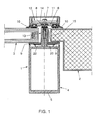
- the curtain wall comprises casings 1 and panels 2, 3.
- the panel 2 is a siding and the panel 3 consists of two layers of glass attached to each other along the outer circumference of the panel.
- Interior, vertical sections of the casing 1 are formed by uprights 4 of the curtain wall. Rear faces 5 of the uprights can be mounted on the bearing structure of the building.
- Exterior, vertical sections of the casing 1 are formed by rails 6. By means of screws 7, the rails 6 are clamped against the uprights 4, with an insulation strip 8 clamped between the rails 6 and the uprights 4.
- the panels 2, 3 are confined between the interior and exterior sections 4 and 6 respectively.
- swelling tape 9 is provided between the panels 2, 3 and the upright 4, which swelling tape swells when heated and then provides extra sealing.
- sealing sections 10 made of rubber and having a heat-resistant composition.
- cover section 11 is provided over the rail 6, on the outside thereof, which, as a matter of fact, forms an initial protection of the rail 6 in the event of fire.
- the panels 2, 3 are held in position by filler strips 15. For clarity's sake, these strips are shown on one side of the upright section 4 only.
- a number of two types of anchors 12, 13 are arranged so as to be distributed over the length of the sections 4, 6, which anchors 12, 13 are both manufactured from stainless steel.
- This material has a higher failure temperature than aluminum, has a higher strength at a slight volume, enabling it to be incorporated into casings according to existing designs, and causes little contact corrosion of the aluminum.
- the anchor 12 shown comprises the screw 7 and a substantially flat plate 14 forming two arms or flanges projecting in opposite directions.
- the screw 7 is inserted into a hole in the plate 14 and clamps the plate 14 against the rail 6.
- the anchor 12 is anchored in place relative to the upright 4, i.e. the interior section.
- the arms formed by the plate 14 overlap the panels 2, 3 on the side opposite the upright 4.
- the arms, formed by the plate 14, of the anchor 12 also retain the rail 6 between that plate 14 and the panels 2, 3, the rail is retained relative to the interior upright 4 for a relatively long time, even when portions of the rail 6 have been attacked by the heat.
- This offers the advantage that an effective sealing along the edge of the panels is maintained for a longer time and the swelling tape 9 is heated less quickly.
- the sealing between the panels 2, 3 and the rail 6 is prevented from already giving way before the swelling tape 9 has been sufficiently heated for swelling and taking over the sealing function of the rail 6.
- the panels 2, 3 are supported more uniformly than when they are exclusively retained directly by the plates 14 of the anchors 12. This also limits the load of the panels 2, 3 themselves, so that they will hold out longer in the event of fire, in particular if additional loads, by wind or explosions, also occur.
- the arms formed by the plate 14 extend to near the sealings 10 between the rail 6 and the panels 2, 3. Accordingly, the sealings 10 are held against the panels even if the rail 6 already deflected in longitudinal direction without support.
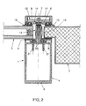
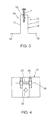
- the anchor 13 of the second type shown is presented separately in Fig. 3.
- This anchor 13 comprises a U-shaped plate element 16 having flanges 18 extending outwardly from free ends of the legs 17 and the screw 7 which it shares in this example with the anchor 12 of the first type and which projects from the bottom 19 of the U-shaped plate element 16.
- the uprights 4 of a curtain wall are generally dimensioned so that they cannot entirely collapse in the case of usual standard fires on the inside of the facade, projecting parts of the uprights 4, such as the outwardly projecting flanges 20, are nevertheless vulnerable enough to collapse prematurely, as a consequence of which the connection with the exterior rails 6 is lost and the panels 2, 3 can fall outside from the casing 1. This is prevented through the use of the anchors 13 of the second type.
- the U-shaped plate element 16 is mounted on the rail 6.
- a hole 22 (see Fig. 4) in the U-shaped plate element 16 through which the screw 7 passes is dimensioned so that the screw engages with the U-shaped plate element 16.
- the rail 6 In the case of fire on the inside of the facade, the rail 6 is located on the cool side of the facade, facing away from the fire, and will hence hold out for a relatively long time.
- the flanges 18 form the arms which overlap the panels 2, 3 on the inside of the curtain wall and which keep the panels 2, 3 clamped against the cool rails 6 so that the hermetic sealing of the facade is maintained for a long time.
- the U-shaped plate element 16 of the anchor 13 of the second type is moreover directly mounted on the upright 4.
- self-tapping screws 21 are passed through holes in the outwardly projecting flanges 18 of the U-shaped plate element 16 and screwed into the uprights 4.
- the anchor 13 of the second type as shown in Fig. 2 moreover has a function in the event of fire on the outside of the facade, as the anchor 12 of the first type is also attached, by means of the scew 7, to the anchor 13 of the second type.
- the flanges 20 of the upright 4 give way, then the anchors 12 of the first type remain coupled, via the anchors 13 of the second type, to the uprights 4, so that the panels 2, 3 are held in place even then.
- the foaming swelling tape 9 ensures that even in the case of small displacements of the panels 2, 3, a proper sealing is still maintained along the edges of the panels 2, 3.
- the attachment of the arms 18 of the anchor 13 of the second type to the interior upright achieves the advantage that portions of the upright 4 are held in position and contribute to the retention of the panels 2, 3 even when other portions of that upright have already given way.
- the longer retention of the uprights 4 in the event of fire on the inside achieves the advantage that the sealing along the edges of the panels is maintained for a longer time and in a better manner, and that the panels 2, 3 are longer supported in a more uniform manner than when the support is directly taken over by the arms 18.
- the swelling tape 9 on the inside of the panel it is important that the swelling tape yields an effective sealing especially as long as and where the uprights 4 are (still) present.
- the arms 18 can be mounted on the upright.
- the arms and the uprights can be constructed so that outer ends of the arms engage behind flanges of or with holes in the upright.
- the plate-shaped portions of the anchors 12, 13 preferably have a length of some centimeters. This is on the one hand sufficient for retaining the panels 2, 3 in position when one of the sections 4, 6 gives way completely or partly, and on the other hand requires only slight amounts of the relatively costly stainless steel.
- the anchor 13 of the second type shown in Fig. 4, comprises a nut 34 and a bolt 23 having a diameter adapted for cooperation with holes 24 (in Figs 3 and 4 indicated by dot and dash lines) in the legs 17, connecting to the bottom 19, of the U-shaped plate element 16 and corresponding holes in the outwardly projecting flanges 20 of the upright 4.
- holes 24 in Figs 3 and 4 indicated by dot and dash lines
- anchors 13 of the second type can be locked in longitudinal direction of the sections 4, 6, if it is desired to provide the anchors 13 at locations where no screws 21 can be provided.
- Fig. 5 shows a variant of a U-shaped plate element 16 for application as part of an anchor 13 of the second type, wherein the legs 17 connecting to the bottom 19 of the U-shaped plate element 16 are of unequal length.
- the distance from the outwardly projecting flanges 18 to the bottom 19 of the U-shaped plate element 16 is different for each of the two flanges.
- This U-shaped plate element 16 is suitable for retaining panels of different thicknesses in position on both sides of casing sections 4, 6.
- Fig. 6 shows a casing system assembled into a casing-panel assembly designed for use as separate casing in an opening in a facade.
- the casing comprises aluminum inside and outside sections 4 and 6 respectively for confining edges of panels 2, 3 therebetween.
- the inside and outside sections 4, 6 are both fixed through rolling to joint coupling sections 25 made from thermally insulating material.
- the resistance to fire on the inside of the casing is increased by distributing local anchors 26 of a third type over the length of the sections 4, 6.
- These anchors 26 of the third type are also manufactured from stainless steel.
- These anchors 26 of the third type are each designed as plate elements flanged so as to be L-shaped and having first and second legs 27, 28, extending at an angle relative to each other, and an outwardly flanged hook edge 29 always provided at an outer end of the second legs 27, 28.
- the flanged hook edges 29 are each anchored to one of the outside sections 6, as they each catch into a groove 30 in the outside section 6.
- the first legs 27, always connecting to the second legs 28 opposite the hook edges 29, each form an arm which, in mounted condition, overlaps one of the panels 2, 3 on the side of the interior section 4.
- the thermally insulating sections 25 give way first, followed by the sections 4 on the inside.
- the panels 2, 3 are still held in position, because the arms 27 overlapping the panels 2, 3 retain the panels 2, 3.
- the flanges of the interior section 4 and sealing rubbers 10 give way, the panels 2, 3 will in fact move away from the exterior section through some distance.
- the foaming swelling tape 9 ensures that a sufficient sealing is nevertheless maintained along the edges of the panels 2, 3.
- the anchors of the third type are used in vertical portions of the casing, it is important that they are anchored in longitudinal direction of the sections 4, 6, preventing the anchors 26 from sliding downwards.
- the anchors 26 can for instance be screwed down, be provided with lips fitting into holes in the exterior section 6, or be provided with a hook edge which is waved in longitudinal direction of the sections 4, 6 and grips in the groove 30 with pretension.
- the arms 27 also extend to near the sealing sections 10 between the section 4 and the panels 2, 3, so that the panels are supported precisely at the location where this is effective for maintaining the sealings along the edges of the panels as long as possible.
- An anchor 26 may also retain a panel 3 in another manner than by the arm 27 for instance by being fastened to the panel with glue or cooperating with a clamp that is clamped over an edge of the panel. It is also possible that the arms 26 are provided with arms 27 and are optionally mounted on the interior sections 4, for instance with self-tapping screws or hook edges.
- the anchors ensure that the interior and exterior sections 4 and 6 are held together, also if the thermally insulating connecting sections 25 give way, while the anchors are not exposed to view all the same.
- the anchors then form brackets which are anchored both to the interior and to the exterior sections 4 and 6 and which bridge the thermally insulating connecting sections 25 for retaining the interior and exterior sections 4 and 6 relative to each other in case the thermally insulating connecting sections give way.
- the section 6 on the outside of the casing is composed of a bearing section 31 and circumferentially closed, tubular glazing bead sections 32, coupled to the bearing section 31 by means of a snap attachment. Since the glazing bead sections 32 are constructed as circumferentially closed, tubular sections, they can resist a greater pressure exerted by the panels than conventional glazing bead sections having separate snap finger flanges catching into the bearing section. These conventional glazing bead sections have to be additionally attached to the bearing sections by means of screws, to be able to resist the pressure exerted by the swelling tape 9 in the event of fire. Owing to the tubular design of the glazing bead sections 32 shown, the provision of screws is not necessary, so that the attachment can be carried out more quickly and no holes which may cause leakage need to be made.
- circumferentially closed, tubular glazing bead sections 32 is also advantageous in combination with other casing sections, which may or may not be provided with anchors for retaining the panels in the event of fire, such as one-piece casing sections without thermally insulating coupling sections.
- one-piece casing sections without thermally insulating coupling sections the heat dissipation in the event of fire is such that the prevailing requirements with regard to fire-resistance can typically be met without special adjustments.
Landscapes
- Engineering & Computer Science (AREA)
- Civil Engineering (AREA)
- Structural Engineering (AREA)
- Architecture (AREA)
- Physics & Mathematics (AREA)
- Electromagnetism (AREA)
- Building Environments (AREA)
- Special Wing (AREA)
- Load-Bearing And Curtain Walls (AREA)
Applications Claiming Priority (2)
| Application Number | Priority Date | Filing Date | Title |
|---|---|---|---|
| NL9401613A NL9401613A (nl) | 1994-09-30 | 1994-09-30 | Brandwerend, aluminium kozijn. |
| NL9401613 | 1994-09-30 |
Publications (2)
| Publication Number | Publication Date |
|---|---|
| EP0704596A1 EP0704596A1 (en) | 1996-04-03 |
| EP0704596B1 true EP0704596B1 (en) | 2003-02-12 |
Family
ID=19864725
Family Applications (1)
| Application Number | Title | Priority Date | Filing Date |
|---|---|---|---|
| EP19950202644 Expired - Lifetime EP0704596B1 (en) | 1994-09-30 | 1995-10-02 | Fire-resistant, aluminium casing |
Country Status (5)
| Country | Link |
|---|---|
| EP (1) | EP0704596B1 (cs) |
| CZ (1) | CZ253295A3 (cs) |
| DE (1) | DE69529594T2 (cs) |
| NL (1) | NL9401613A (cs) |
| PL (1) | PL181497B1 (cs) |
Families Citing this family (13)
| Publication number | Priority date | Publication date | Assignee | Title |
|---|---|---|---|---|
| DE4438113A1 (de) * | 1994-10-26 | 1996-05-02 | Eberspaecher J | Brandsichere Halterung mindestens einer Scheibe |
| DE29500148U1 (de) * | 1995-01-05 | 1996-05-09 | Niemann, Hans Dieter, 50169 Kerpen | Rahmenprofil für Fenster oder Türen |
| AT406075B (de) * | 1998-01-26 | 2000-02-25 | Degelsegger Walter Ing | Verglasung |
| BE1014372A3 (nl) | 2001-09-18 | 2003-09-02 | Reynaers Aluminium Nv | Brandwerend kozijn-paneel samenstel. |
| IE20060153A1 (en) * | 2006-03-02 | 2007-11-14 | Architectural & Metal Systems | Walling system |
| DE202006004607U1 (de) * | 2006-03-21 | 2006-06-01 | SCHÜCO International KG | Rahmenkonstruktion für ein aus Rahmenholmen zusammengesetztes Bauelement |
| DE202006004606U1 (de) | 2006-03-21 | 2006-06-08 | SCHÜCO International KG | Rahmenkonstruktion |
| EP1860250B1 (de) * | 2006-05-26 | 2014-12-03 | Raico Bautechnik GmbH | Aufsatzdichtung |
| DE102012004297B4 (de) | 2012-03-01 | 2019-01-10 | Hueck Gmbh & Co. Kg | Profilanordnung und Rahmenkonstruktion |
| CH708354B1 (de) | 2013-07-16 | 2017-08-31 | Saint Gobain | Brandschutzbauteil |
| PL233265B1 (pl) * | 2017-09-29 | 2019-09-30 | Carboline Polska Spolka Z Ograniczona Odpowiedzialnoscia | Niepalna termoaktywna osłona ognioochronna |
| DE102019133839A1 (de) * | 2019-12-10 | 2021-06-10 | SCHÜCO International KG | Bauelement in Brandschutzausführung und Verfahren zur Montage eines Bauelementes |
| US20230228082A1 (en) * | 2022-01-20 | 2023-07-20 | O'keeffe's, Inc. | Glazed Curtain Wall Panel System |
Family Cites Families (6)
| Publication number | Priority date | Publication date | Assignee | Title |
|---|---|---|---|---|
| FR1264130A (fr) * | 1959-06-16 | 1961-06-19 | Hills West Bromwich Ltd | Ensemble vitré utilisable notamment dans le bâtiment |
| US3797191A (en) * | 1972-10-20 | 1974-03-19 | American Metal Climax Inc | Wall construction |
| US4550542A (en) * | 1984-08-09 | 1985-11-05 | Jack La See | Vision panel frame |
| DE8902212U1 (de) * | 1989-02-24 | 1989-05-03 | Fa. J. Eberspächer, 7300 Esslingen | Vorrichtung zur Halterung von unter thermischer Belastung sich plastisch verformenden ebenen Bauteilen an Gebäuden |
| DE9107171U1 (de) * | 1991-06-11 | 1992-07-16 | W. Hartmann & Co (Gmbh & Co), 2000 Hamburg | Pfosten- und Riegelprofilgerüst für eine mit Flächenelementen ausgefachte Wand- oder Deckenkonstruktion |
| DE9300692U1 (de) * | 1993-01-20 | 1994-05-26 | Schmidlin Ag, Aesch | Dichtungsprofil |
-
1994
- 1994-09-30 NL NL9401613A patent/NL9401613A/nl not_active Application Discontinuation
-
1995
- 1995-09-29 PL PL31072795A patent/PL181497B1/pl not_active IP Right Cessation
- 1995-09-29 CZ CZ952532A patent/CZ253295A3/cs unknown
- 1995-10-02 DE DE1995629594 patent/DE69529594T2/de not_active Expired - Lifetime
- 1995-10-02 EP EP19950202644 patent/EP0704596B1/en not_active Expired - Lifetime
Also Published As
| Publication number | Publication date |
|---|---|
| DE69529594D1 (de) | 2003-03-20 |
| PL310727A1 (en) | 1996-04-01 |
| DE69529594T2 (de) | 2003-12-18 |
| EP0704596A1 (en) | 1996-04-03 |
| CZ253295A3 (en) | 1996-04-17 |
| NL9401613A (nl) | 1996-05-01 |
| PL181497B1 (pl) | 2001-07-31 |
Similar Documents
| Publication | Publication Date | Title |
|---|---|---|
| EP0704596B1 (en) | Fire-resistant, aluminium casing | |
| US10920416B2 (en) | Drywall and sealing device for sealing a connection joint of a drywall | |
| US11808036B2 (en) | Thermal and acoustic insulating and sealing system for a safing slot in a curtain wall | |
| US10633858B2 (en) | Prefabricated curtain wall assembly | |
| US11898348B2 (en) | Curtain wall L-bracket and clip assembly | |
| US5355645A (en) | Stopless butt-joint multiple curtainwall system | |
| US20070204540A1 (en) | Means and method for fireproof sealing between the peripheral edge of individual floors of a building and the exterior wall structure thereof | |
| US11834826B2 (en) | Building facade system and method of forming a building facade | |
| US10519653B2 (en) | Facade assembly, building structure, and method for mounting the facade assembly | |
| US20180030724A1 (en) | Facade assembly, building structure and method for mounting the facade assembly | |
| US10724233B2 (en) | Curtain wall saddle-bracket and clip assembly | |
| CA2003593C (en) | Access opening closure assembly | |
| US10626603B2 (en) | Curtain wall saddle bracket and clip assembly | |
| US6367212B1 (en) | Fire-retardant roof construction | |
| JPH0440498B2 (cs) | ||
| JPH1136726A (ja) | 窓框の窓体取付構造 | |
| JP2766221B2 (ja) | カーテンウォール | |
| KR200417025Y1 (ko) | 방화유리가 부착되는 구조를 갖는 발코니 난간 | |
| GB2224767A (en) | Glazed fire-resistant screen |
Legal Events
| Date | Code | Title | Description |
|---|---|---|---|
| PUAI | Public reference made under article 153(3) epc to a published international application that has entered the european phase |
Free format text: ORIGINAL CODE: 0009012 |
|
| AK | Designated contracting states |
Kind code of ref document: A1 Designated state(s): BE CH DE ES GB IE LI NL |
|
| AX | Request for extension of the european patent |
Free format text: LT;LV;SI |
|
| RAX | Requested extension states of the european patent have changed |
Free format text: LT;LV;SI |
|
| RBV | Designated contracting states (corrected) |
Designated state(s): BE CH DE ES GB IE LI NL |
|
| 17P | Request for examination filed |
Effective date: 19961002 |
|
| 17Q | First examination report despatched |
Effective date: 19980917 |
|
| GRAG | Despatch of communication of intention to grant |
Free format text: ORIGINAL CODE: EPIDOS AGRA |
|
| GRAG | Despatch of communication of intention to grant |
Free format text: ORIGINAL CODE: EPIDOS AGRA |
|
| GRAH | Despatch of communication of intention to grant a patent |
Free format text: ORIGINAL CODE: EPIDOS IGRA |
|
| GRAH | Despatch of communication of intention to grant a patent |
Free format text: ORIGINAL CODE: EPIDOS IGRA |
|
| GRAA | (expected) grant |
Free format text: ORIGINAL CODE: 0009210 |
|
| AK | Designated contracting states |
Designated state(s): BE CH DE ES GB IE LI NL |
|
| PG25 | Lapsed in a contracting state [announced via postgrant information from national office to epo] |
Ref country code: LI Free format text: LAPSE BECAUSE OF FAILURE TO SUBMIT A TRANSLATION OF THE DESCRIPTION OR TO PAY THE FEE WITHIN THE PRESCRIBED TIME-LIMIT Effective date: 20030212 Ref country code: CH Free format text: LAPSE BECAUSE OF FAILURE TO SUBMIT A TRANSLATION OF THE DESCRIPTION OR TO PAY THE FEE WITHIN THE PRESCRIBED TIME-LIMIT Effective date: 20030212 |
|
| REG | Reference to a national code |
Ref country code: GB Ref legal event code: FG4D |
|
| REG | Reference to a national code |
Ref country code: CH Ref legal event code: EP |
|
| REF | Corresponds to: |
Ref document number: 69529594 Country of ref document: DE Date of ref document: 20030320 Kind code of ref document: P |
|
| REG | Reference to a national code |
Ref country code: IE Ref legal event code: FG4D |
|
| PG25 | Lapsed in a contracting state [announced via postgrant information from national office to epo] |
Ref country code: ES Free format text: LAPSE BECAUSE OF FAILURE TO SUBMIT A TRANSLATION OF THE DESCRIPTION OR TO PAY THE FEE WITHIN THE PRESCRIBED TIME-LIMIT Effective date: 20030828 |
|
| REG | Reference to a national code |
Ref country code: CH Ref legal event code: PL |
|
| PLBE | No opposition filed within time limit |
Free format text: ORIGINAL CODE: 0009261 |
|
| STAA | Information on the status of an ep patent application or granted ep patent |
Free format text: STATUS: NO OPPOSITION FILED WITHIN TIME LIMIT |
|
| 26N | No opposition filed |
Effective date: 20031113 |
|
| BECA | Be: change of holder's address |
Owner name: ALCOA NEDERLAND B.V.ALCOALAAN 1, NL-5151 RW DRUNEN Effective date: 20091218 |
|
| NLS | Nl: assignments of ep-patents |
Owner name: REYNOLDS EXTRUSION EUROPE (HOLDING) B.V. Effective date: 20091028 Owner name: ALCOA NEDERLAND B.V. Effective date: 20091028 |
|
| PGFP | Annual fee paid to national office [announced via postgrant information from national office to epo] |
Ref country code: NL Payment date: 20101018 Year of fee payment: 16 Ref country code: IE Payment date: 20101027 Year of fee payment: 16 |
|
| PGFP | Annual fee paid to national office [announced via postgrant information from national office to epo] |
Ref country code: GB Payment date: 20101029 Year of fee payment: 16 |
|
| PGFP | Annual fee paid to national office [announced via postgrant information from national office to epo] |
Ref country code: DE Payment date: 20101230 Year of fee payment: 16 |
|
| PGFP | Annual fee paid to national office [announced via postgrant information from national office to epo] |
Ref country code: BE Payment date: 20111013 Year of fee payment: 17 |
|
| REG | Reference to a national code |
Ref country code: NL Ref legal event code: V1 Effective date: 20120501 |
|
| GBPC | Gb: european patent ceased through non-payment of renewal fee |
Effective date: 20111002 |
|
| PG25 | Lapsed in a contracting state [announced via postgrant information from national office to epo] |
Ref country code: NL Free format text: LAPSE BECAUSE OF NON-PAYMENT OF DUE FEES Effective date: 20120501 Ref country code: DE Free format text: LAPSE BECAUSE OF NON-PAYMENT OF DUE FEES Effective date: 20120501 |
|
| REG | Reference to a national code |
Ref country code: IE Ref legal event code: MM4A |
|
| REG | Reference to a national code |
Ref country code: DE Ref legal event code: R119 Ref document number: 69529594 Country of ref document: DE Effective date: 20120501 |
|
| PG25 | Lapsed in a contracting state [announced via postgrant information from national office to epo] |
Ref country code: GB Free format text: LAPSE BECAUSE OF NON-PAYMENT OF DUE FEES Effective date: 20111002 |
|
| PG25 | Lapsed in a contracting state [announced via postgrant information from national office to epo] |
Ref country code: IE Free format text: LAPSE BECAUSE OF NON-PAYMENT OF DUE FEES Effective date: 20111002 |
|
| BERE | Be: lapsed |
Owner name: ALCOA NEDERLAND B.V. Effective date: 20121031 |
|
| PG25 | Lapsed in a contracting state [announced via postgrant information from national office to epo] |
Ref country code: BE Free format text: LAPSE BECAUSE OF NON-PAYMENT OF DUE FEES Effective date: 20121031 |