EP0704255B1 - Device for reversing the transport direction of flat mail objects - Google Patents
Device for reversing the transport direction of flat mail objects Download PDFInfo
- Publication number
- EP0704255B1 EP0704255B1 EP95113897A EP95113897A EP0704255B1 EP 0704255 B1 EP0704255 B1 EP 0704255B1 EP 95113897 A EP95113897 A EP 95113897A EP 95113897 A EP95113897 A EP 95113897A EP 0704255 B1 EP0704255 B1 EP 0704255B1
- Authority
- EP
- European Patent Office
- Prior art keywords
- transport rollers
- transport
- rotation
- fence
- Prior art date
- Legal status (The legal status is an assumption and is not a legal conclusion. Google has not performed a legal analysis and makes no representation as to the accuracy of the status listed.)
- Expired - Lifetime
Links
Images


Classifications
-
- B—PERFORMING OPERATIONS; TRANSPORTING
- B07—SEPARATING SOLIDS FROM SOLIDS; SORTING
- B07C—POSTAL SORTING; SORTING INDIVIDUAL ARTICLES, OR BULK MATERIAL FIT TO BE SORTED PIECE-MEAL, e.g. BY PICKING
- B07C1/00—Measures preceding sorting according to destination
- B07C1/20—Sorting according to orientation, e.g. according to position of stamp
-
- B—PERFORMING OPERATIONS; TRANSPORTING
- B65—CONVEYING; PACKING; STORING; HANDLING THIN OR FILAMENTARY MATERIAL
- B65H—HANDLING THIN OR FILAMENTARY MATERIAL, e.g. SHEETS, WEBS, CABLES
- B65H15/00—Overturning articles
- B65H15/016—Overturning articles employing rotary or reciprocating elements supporting transport means
-
- B—PERFORMING OPERATIONS; TRANSPORTING
- B65—CONVEYING; PACKING; STORING; HANDLING THIN OR FILAMENTARY MATERIAL
- B65H—HANDLING THIN OR FILAMENTARY MATERIAL, e.g. SHEETS, WEBS, CABLES
- B65H2701/00—Handled material; Storage means
- B65H2701/10—Handled articles or webs
- B65H2701/19—Specific article or web
- B65H2701/1916—Envelopes and articles of mail
Definitions
- the present invention relates to a device for reversing the transport direction of flat mail items for mail distribution systems.
- a problem in mail distribution systems in which flat mail items are supplied with character recognition and marking devices in order to distribute the mail items in accordance with various information applied to their surface is that part of the mail items is transported in the conveying means in such a way that the information item is provided with the information Surface is not arranged in the processing position opposite the character recognition and identification means.
- a shipment that is not in the processing position can be brought into the working position by rotating the shipment about the longitudinal axis and / or the vertical axis.
- a problem that arises with such rotations is that the gaps between the consignments or the distances between the front or rear edges of the consignment are changed by the operation of the rotation, possibly even overlapping of consignments, which can lead to blockages and functional failure of the system.
- DE 43 15 053 already provides a device for reversing the direction known from flat shipments, with funding for feeding the items at a first speed and other funding for the removal of the shipments with a second speed, the first funding for Feeding the shipments with a first predetermined Speed in the second funding to accommodate the Shipments and detection means for determining the time, to which the trailing edge of a broadcast, the first Funding has left, are provided. Every shipment is specified in the second funding with the first Speed recorded and as soon as their trailing edge the has left the first funding, according to a predetermined Decelerated speed profile. Then there is a reversal the direction of conveyance and an acceleration of the shipment to a second predetermined speed. Third party funding are to record the programs from the second Funding at the second predetermined speed provided, the programs in the first, second and third grants managed non-positively at all times become.
- FR-A 2315131 describes a device for billets, which measures which side is on Magnetic stripe is located. Depending on the location of the magnetic stripe then the ticket between two fence elements (guide elements), driven by the transport rollers, directly without Rotation transported or there is a rotation of the fence elements around 180 ° with a special mechanism. Is located only one ticket and only one in the device after emptying, a new ticket can be inserted into the described one Device can be included.
- the object of the present invention is a device to create quickly and with the shipments around their vertical axis can be rotated safely.
- the object is characterized by the features of the independent Claim 1 solved, advantageous training of the invention are in the dependent claims and the description contain.
- Particularly advantageous in the case of the invention Device is that the shipments are inside the device run smoothly and safely. The shipments remain always grasped and are never left to their own devices. Thereby high precision of the movement of the items is achieved and program run disruptions prevented. This device brakes and accelerates the mail items gently. The device is also particularly space-saving.
- the rotation of the Shipments are made in such a way that the gaps in the shipment flow before and after the rotation of the programs are the same or but not the gaps in the shipment, but the distances between the or trailing edges constant before and after the rotation stay.
- Device 3a In the basic structure shown in Fig. 1 Device 3a according to the invention first of all from the feeding conveying means 1 to the device handed over for reversal. Usually they exist Funding 1 from conveyor belts, between which the Consignments are moved upright.
- the reversing device essentially has two symmetrically arranged Fence elements 4, 5, between which one Transport roller 3 is arranged. The transport roller and the Fence elements are in an area between the funding 1 and the discharging conveyors 2 rotatable about an axis A. arranged.
- the fence elements 4, 5 are essentially parallel to each other and arranged tangentially to the transport roller. Every fence element forms an essentially linear elongated and at one end angled sliding surface for the consignments.
- the the two fence elements are point symmetrical to each other arranged to the axis of rotation A that they together form a transport channel form, whose cross section is in the area of the angled Part of each fence element reduced.
- Transport roller 3 and fence elements 4, 5 are the same Axis A rotatable.
- Each fence element consists of a section with a bend and a section that in is essentially linear. From the common Axis A of the transport roller and fence element seen from the angled section of each fence element extends less far than the linear section of each opposite fence element.
- the linear section of a Fence element serves as a receiving surface for the feed the consignments and when the consignments are removed as a removal area. It is advantageous that this part of the Inclusion or discharge of the programs in the area of the supply or discharge conveying means protrudes, that ensures a safe recording or removal of the shipment is.
- the end region of this section preferably protrudes the conveyor belts 1a and 2a. Fixing everyone in the Radius of the fence elements 4,5 protruding rollers and Conveyor belts are designed so that there are no collisions occur with the fence elements 4, 5.
- each fence element is used to Shipments where there is no reversal of the direction of transport is provided at the undiminished speed to the to transfer laxative funds. From the angled one Part of each fence element is one such continuous program against the linear section of the opposite fence element steered from which it is sliding is transferred to the laxative funding 2.
- the transport roller 3 is between the two fence elements 4 and 5 arranged such that a flat consignment is non-positive between the transport roller 3 and a fence element 4, 5 is feasible. This essentially requires choosing one suitable distance between the transport roller and the fence element as well as resilient sliding surfaces 7 in the area of each fence element, in which the shipments between the fence element and Transport roller be guided non-positively.
- the transport roller 3 Speed transported to the discharging funds 2.
- the transport roller 3 is one with the Speed of delivery of the items adjusted speed operated.
- the one between the transport roller 3 and the fence 4 The letter transported in a force-fitting manner becomes linear elongated part of the fence 4 to the angled area moved and towards the opposite linear Section of the fence 5 steered.
- C denotes a possible trajectory of the rear edge of the mail item during the turning process.
- the deviation from a circular path around the axis A results from the during the rotational movement of the shipment between Fence element 4 and transport roller 3.
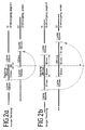
- FIG. 2 illustrates the dynamic processes that typically occur when operating the device.
- the Device can process shipments of different lengths. Shipment lengths between 135 mm are an example and adopted 295 mm; the gaps between the continuously mail items supplied are, for example, 100 mm each at a feed speed of 3 m / s.
- Figure 2b shows the case of a long shipment. At the time t1 the rotation is initiated, which in turn lasts 37 ms.
- the two representations 2a and 2b show that, in the example under consideration, t2 must be selected such that at this point in time the left edge of the letter is 111 mm further away from the axis of rotation A than the right.
- This path of 111 mm corresponds to a rotation time of 37 ms at 3 m / s.
- t 180 l min - l klem, min V , where V denotes the transport speed and l min the length of the shortest letter to be processed.
- l klem, min is the minimum clamping length required for secure contact between the transport roller and the consignment, cf. Figure 2a.
- FIG. 3 shows a sectional view along the length X-X in FIG. 1.
- the device is then mechanically driven two electric motors 8, 9 based on the same geometric Axis A are arranged.
- the torque of the motor 8 is via a hollow shaft 10, which surrounds a shaft 11, to the Fence elements 4, 5 and passed on to the transport roller 3. It is advantageous to avoid unnecessary moments of inertia:
- the fence elements 4, 5 can be designed as a wire frame become.
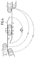
- FIG. 4 shows a further embodiment of the invention shown.
- the rollers 12 and 13 are advantageous with an endless belt 14 provided to better guidance of the program 3a guarantee.
- the letters are taken earlier by one of the transport rollers 12, 13 seized so that the rotary movement can be started earlier can and may take a long time. Therefore, with This arrangement takes advantage of the time required for a 180 ° turn the fence elements are available, extended become.
- Figure 5 shows another embodiment of the mechanical Drive for the device according to the invention. After that is done a transmission of the torque of the motor 14 via the shaft 16 or, the motor 15 via the drive belt 17 on the Hollow shaft 18 on the transport roller or the fence elements. As in FIG. 3, the shafts are supported in bearings 19.
Landscapes
- Engineering & Computer Science (AREA)
- Mechanical Engineering (AREA)
- Registering Or Overturning Sheets (AREA)
- Attitude Control For Articles On Conveyors (AREA)
- Delivering By Means Of Belts And Rollers (AREA)
- Separation, Sorting, Adjustment, Or Bending Of Sheets To Be Conveyed (AREA)
- Manufacturing And Processing Devices For Dough (AREA)
- Sorting Of Articles (AREA)
Abstract
Description
Die vorliegende Erfindung betrifft eine Vorrichtung zur
Umkehrung der Transportrichtung von flachen Sendungen für
Briefverteilanlagen.
In Briefverteilanlagen, in denen flache Sendungen Zeichenerkennungs-
und Kennzeichnungseinrichtungen zugeführt werden,
um die Sendungen entsprechend verschiedener auf ihrer Oberfläche
aufgebrachter Informationen zu verteilen, besteht ein
Problem darin, daß ein Teil der Sendungen derart in den Fördermitteln
transportiert wird, daß die mit der Information
versehene Oberfläche nicht in Bearbeitungsposition gegenüber
den Zeichenerkennungs- und Kennzeichnungsmitteln angeordnet
ist. Eine nicht in Bearbeitungsposition befindliche Sendung
kann durch eine Drehung der Sendung um die Längsachse
und/oder die Hochachse in Arbeitsposition gebracht werden.
Ein bei solchen Drehungen auftretendes Problem besteht darin,
daß die Lücken zwischen den Sendungen bzw. Abständen zwischen
Sendungsvorder- oder Hinterkanten durch die Operation der
Drehung verändert werden, evtl. sogar Überlappungen von
Sendungen auftreten, was zu Verstopfungen und Funktionsausfall
der Anlage führen kann.The present invention relates to a device for reversing the transport direction of flat mail items for mail distribution systems.
A problem in mail distribution systems in which flat mail items are supplied with character recognition and marking devices in order to distribute the mail items in accordance with various information applied to their surface is that part of the mail items is transported in the conveying means in such a way that the information item is provided with the information Surface is not arranged in the processing position opposite the character recognition and identification means. A shipment that is not in the processing position can be brought into the working position by rotating the shipment about the longitudinal axis and / or the vertical axis. A problem that arises with such rotations is that the gaps between the consignments or the distances between the front or rear edges of the consignment are changed by the operation of the rotation, possibly even overlapping of consignments, which can lead to blockages and functional failure of the system.
Aus der DE 43 15 053 ist bereits eine Vorrichtung zur Richtungsumkehr von flachen Sendungen bekannt, mit Fördermitteln zur Zuführung der Sendungen mit einer ersten Geschwindigkeit und weiteren Fördermitteln zur Abfuhr der Sendungen mit einer zweiten Geschwindigkeit, wobei die ersten Fördermittel zur Zuführung der Sendungen mit einer ersten vorgegebenen Geschwindigkeit in die zweiten Fördermittel zur Aufnahme der Sendungen und Detektionsmittel zur Bestimmung des Zeitpunktes, zu dem die Hinterkante einer Sendung, die die ersten Fördermittel verlassen hat, vorgesehen sind. Jede Sendung wird in den zweiten Fördermitteln mit der ersten vorgegebenen Geschwindigkeit aufgenommen und sobald ihre Hinterkante die ersten Fördermittel verlassen hat, nach einem vorgegebenen Geschwindigkeitsprofil abgebremst. Daraufhin erfolgt eine Umkehrung der Förderrichtung und eine Beschleunigung der Sendung auf eine zweite vorgegebene Geschwindigkeit. Dritte Fördermittel sind zur Aufnahme der Sendungen aus den zweiten Fördermitteln mit der zweiten vorgegebenen Geschwindigkeit vorgesehen, wobei die Sendungen in den ersten, zweiten und dritten Fördermitteln zu jedem Zeitpunkt kraftschlüssig geführt werden.DE 43 15 053 already provides a device for reversing the direction known from flat shipments, with funding for feeding the items at a first speed and other funding for the removal of the shipments with a second speed, the first funding for Feeding the shipments with a first predetermined Speed in the second funding to accommodate the Shipments and detection means for determining the time, to which the trailing edge of a broadcast, the first Funding has left, are provided. Every shipment is specified in the second funding with the first Speed recorded and as soon as their trailing edge the has left the first funding, according to a predetermined Decelerated speed profile. Then there is a reversal the direction of conveyance and an acceleration of the shipment to a second predetermined speed. Third party funding are to record the programs from the second Funding at the second predetermined speed provided, the programs in the first, second and third grants managed non-positively at all times become.
In der FR-A 2315131 ist eine Vorrichtung für Billets beschrieben, bei der gemessen wird, auf welcher Seite sich ein Magnetstreifen befindet. Je nach Lage des Magnetstreifens wird dann das Billett zwischen zwei Zaunelementen (Leitelemente), angetrieben durch die Transportrollen, direkt ohne Drehung transportiert oder es erfolgt eine Drehung der Zaunelemente um 180° mit einer speziellen Mechanik. Dabei befindet sich in der Vorrichtung immer nur ein Billet und erst nach der Entleerung kann wieder ein neues Billet in die beschriebene Vorrichtung aufgenommen werden.FR-A 2315131 describes a device for billets, which measures which side is on Magnetic stripe is located. Depending on the location of the magnetic stripe then the ticket between two fence elements (guide elements), driven by the transport rollers, directly without Rotation transported or there is a rotation of the fence elements around 180 ° with a special mechanism. Is located only one ticket and only one in the device after emptying, a new ticket can be inserted into the described one Device can be included.
Aufgabe der vorliegenden Erfindung ist es, eine Vorrichtung zu schaffen, mit der Sendungen um ihre Hochachse schnell und sicher gedreht werden können.The object of the present invention is a device to create quickly and with the shipments around their vertical axis can be rotated safely.
Erfindungsgemäß wird die Aufgabe durch die Merkmale des unabhängigen
Patentanspruches 1 gelöst, vorteilhafte Ausbildungen
der Erfindung sind in den Unteransprüchen und der Beschreibung
enthalten. Besonders vorteilhaft bei der erfindungsgemäßen
Vorrichtung ist, daß die Sendungen innerhalb der Vorrichtung
stoßfrei und sicher geführt werden. Die Sendungen bleiben
stets erfaßt und sind nie sich selbst überlassen. Dadurch
wird eine hohe Präzision der Bewegung der Sendungen erreicht
und Sendungslaufstörungen vorgebeugt. Diese Vorrichtung
bremst und beschleunigt die Sendungen briefschonend. Die Vorrichtung
ist außerdem besonders platzsparend. Die Drehung der
Sendungen erfolgt in einer Weise, daß die Lücken im Sendungsstrom
vor und nach der Drehung der Sendungen gleich sind oder
aber nicht die Sendungslücken, sondern die Abstände der Sendungsvorder-
oder Hinterkanten vor und nach der Drehung konstant
bleiben. According to the invention, the object is characterized by the features of the
Im folgenden wird die Erfindung anhand der Figuren 1 bis 5 näher erläutert. Dabei zeigt
Figur 1- eine Prinzipdarstellung einer erfindungsgemäßen Vorrichtung in Draufsicht,
Figur 2a und 2b- eine Darstellung der zeitlichen Verhältnisse bei langen und kurzen Sendungen,
Figur 3- ein Schnittbild X-X gemäß
Figur 1, - Figur 4
- eine Prinzipdarstellung einer weiteren erfindungsgemäßen Vorrichtung,
Figur 5- eine Prinzipdarstellung eines alternativen Antriebsystems für eine erfindungsgemäße Vorrichtung.
- Figure 1
- 1 shows a schematic diagram of a device according to the invention in plan view,
- Figure 2a and 2b
- a representation of the temporal relationships for long and short programs,
- Figure 3
- 2 shows a sectional view XX according to FIG. 1,
- Figure 4
- a schematic diagram of a further device according to the invention,
- Figure 5
- a schematic diagram of an alternative drive system for a device according to the invention.
Bei der in Fig. 1 in ihrem prinzipiellen Aufbau gezeigten
erfindungsgemäßen Vorrichtung werden die Sendungen 3a
zunächst von den zuführenden Fördermitteln 1 an die Vorrichtung
zur Umkehrung übergeben. Üblicherweise bestehen die
Fördermittel 1 aus Transportbändern, zwischen denen die
Sendungen aufrecht stehend bewegt werden. Die Umkehrvorrichtung
weist im wesentlichen zwei zueinander symmetrisch angeordnete
Zaunelemente 4, 5 auf, zwischen denen eine
Transportrolle 3 angeordnet ist. Die Transportrolle und die
Zaunelemente sind in einem Bereich zwischen den Fördermitteln
1 und den abführenden Fördermitteln 2 drehbar um eine Achse A
angeordnet.In the basic structure shown in Fig. 1
Die Zaunelemente 4, 5 sind im wesentlichen parallel zueinander
und tangential zur Transportrolle angeordnet. Jedes Zaunelement
bildet eine im wesentlichen linear langgestreckte und
an einem Ende abgewinkelte Gleitfläche für die Sendungen. Die
beiden Zaunelemente sind zueinander punktsymmetrisch derart
zur Drehachse A angeordnet, daß sie zusammen einen Transportkanal
bilden, dessen Querschnitt sich im Bereich des abgewinkelten
Teils jedes Zaunelements verringert.The
Transportrolle 3 und Zaunelemente 4, 5 sind um die gleiche
Achse A drehbar. Jedes Zaunelement besteht aus einem Teilabschnitt
mit einer Abwinklung und einem Teilabschnitt, der im
wesentlichen linear ausgebildet ist. Von der gemeinsamen
Achse A der Transportrolle und Zaunelement aus gesehen,
erstreckt sich der abgewinkelte Teilabschnitt jedes Zaunelements
weniger weit als der lineare Teilabschnitt des jeweils
gegenüber liegenden Zaunelements. Der lineare Abschnitt eines
Zaunelements dient bei der Zuführung als Aufnahmefläche für
die Sendungen und bei der Abführung der Sendungen als Abführfläche.
Dazu ist es vorteilhaft, daß dieser Teil bei der
Aufnahme bzw. Abführung der Sendungen derart in den Bereich
des zuführenden bzw. abführenden Fördermittels hineinragt,
daß eine sichere Aufnahme bzw. Abführung der Sendung gewährleistet
ist. Bei der Verwendung von Transportbändern 1a, 2a,
zwischen denen die Sendungen aufrecht stehend bewegt werden,
ragt der Endbereich dieses Teilabschnitts vorzugsweise über
die Transportbänder 1a bzw. 2a. Die Befestigung aller in den
Radius der Zaunelemente 4,5 hineinragenden Rollen und
Transportbänder ist dabei so gestaltet, daß keine Kollisionen
mit den Zaunelementen 4, 5 auftreten.
Der abgewinkelte Teilabschnitt jedes Zaunelements dient dazu,
Sendungen, bei denen keine Umkehrung der Transportrichtung
vorgesehen ist, mit unverminderter Geschwindigkeit an die
abführenden Fördermittel 2 zu übergeben. Von dem abgewinkelten
Teilabschnitt jedes Zaunelements wird dabei eine derart
durchlaufende Sendung gegen den linearen Teilabschnitt des
gegenüberliegenden Zaunelements gelenkt, von dem es gleitend
an das abführende Fördermittel 2 übergeben wird. The angled section of each fence element is used to
Shipments where there is no reversal of the direction of transport
is provided at the undiminished speed to the
to transfer laxative funds. From the angled one
Part of each fence element is one such
continuous program against the linear section of the
opposite fence element steered from which it is sliding
is transferred to the
Die Transportrolle 3 ist zwischen den beiden Zaunelementen 4
und 5 derart angeordnet, daß eine flache Sendung kraftschlüssig
zwischen der Transportrolle 3 und einem Zaunelement 4, 5
führbar ist. Dies erfordert im wesentlichen die Wahl eines
geeigneten Abstands zwischen Transportrolle und Zaunelement
sowie federnde Gleitflächen 7 in dem Bereich jedes Zaunelements,
in dem die Sendungen zwischen Zaunelement und
Transportrolle kraftschlüssig geführt werden.The
Bei der Arbeitsweise der erfindungsgemäßen Vorrichtung ist zwischen zwei Fällen zu unterscheiden.In the operation of the device according to the invention distinguish between two cases.
Soll die Sendung nicht um die Hochachse gedreht werden, so
wird sie durch die Transportrolle 3 mit unverminderter
Geschwindigkeit an die abführenden Fördermittel 2 transportiert.
Die Transportrolle 3 wird dabei mit einer an die
Zuführungsgeschwindigkeit der Sendungen angepaßten Drehzahl
betrieben. Der zwischen Transportrolle 3 und dem Zaun 4
kraftschlüssig transportierte Brief wird dabei von dem linear
langgestreckten Teils des Zauns 4 zum abgewinkelten Bereich
bewegt und in Richtung auf den gegenüberliegenden linearen
Teilabschnitt des Zauns 5 gelenkt.If the shipment is not to be rotated about the vertical axis, then so
it is undiminished by the
Soll die Sendung um ihre Hochachse gedreht werden, so führen
die Zaunelemente eine Drehung um 180° um die Achse A aus. Die
Drehung beginnt frühestens, sobald die Hinterkante der
Sendung die Fördermittel 1 verlassen hat und dies von in Fig.
1 nicht dargestellten Detektionsmitteln festgestellt wurde.
Während diese 180°-Drehung ausgeführt wird, wird die
Geschwindigkeit der Transportrolle negiert. Die Sendung wird
daraufhin von der Transportrolle entlang des linear langgestreckten
Teils des Zauns 4 bewegt und nach Beendigung der
Drehung stoßfrei an die Fördermittel 2 übergeben. Sobald die
Sendung den Kontakt zur Transportrolle 3 verliert, wird deren
Geschwindigkeit wieder umgekehrt, um für die Aufnahme der
nächsten Sendung bereit zu sein. Der Kontakt zwischen Sendung
und Transportrolle wird von nicht in Fig. 1 dargestellten
Detektionsmitteln überwacht. Die Folgesendung darf die
Fördermittel 1 schon teilweise verlassen haben, also in den
Schwenkbereich der Zaunelemente hineinragen, wenn die 180°-Drehung
vollendet ist. Dies ermöglicht eine Verminderung der
kleinsten sicher verarbeitbaren Sendungslücke.If the shipment is to be rotated around its vertical axis, then guide it
the fence elements rotate through 180 ° around the axis A. The
At the earliest, rotation begins as soon as the rear edge of the
Program has left the
In Figur 1 bezeichnet C eine mögliche Bahnkurve der Sendungshinterkante
während des Drehvorgangs. Die Abweichung von
einer Kreisbahn um die Achse A ergibt sich aus der während
der Drehbewegung ausgeführten Bewegung der Sendung zwischen
Zaunelement 4 und Transportrolle 3.In Figure 1, C denotes a possible trajectory of the rear edge of the mail item
during the turning process. The deviation from
a circular path around the axis A results from the during
the rotational movement of the shipment between
Fence element 4 and
In Figur 2 werden die dynamischen Vorgänge verdeutlicht, die bei Betreiben der Vorrichtung typischerweise auftreten. Die Vorrichtung kann Sendungen mit unterschiedlicher Länge bearbeiten. Beispielhaft werden Sendungslängen zwischen 135 mm und 295 mm angenommen; die Lücken zwischen den kontinuierlich zugeführten Sendungen betragen beispielsweise jeweils 100 mm bei einer Zuführgeschwindigkeit von 3 m/s. Die Figur 2a zeigt den Fall einer kurzen Sendung. Zum Zeitpunkt t1 wird die 180°-Drehung eingeleitet. Die Sendung ist zu diesem Zeitpunkt schon fest von der Transportrolle erfaßt. Zum Zeitpunkt t2 = t1 + 37 ms ist der Drehvorgang abgeschlossen und die Sendung wird in den Sendungsstrom eingegliedert ohne ihre relative Positionen verändert zu haben.FIG. 2 illustrates the dynamic processes that typically occur when operating the device. The Device can process shipments of different lengths. Shipment lengths between 135 mm are an example and adopted 295 mm; the gaps between the continuously mail items supplied are, for example, 100 mm each at a feed speed of 3 m / s. Figure 2a shows the case of a short broadcast. At time t1 180 ° rotation initiated. The shipment is at this time already gripped by the transport roller. At time t2 = t1 + 37 msec the turning process is complete and the broadcast is incorporated into the shipment stream without its relative To have changed positions.
Figur 2b zeigt den Fall einer langen Sendung. Zum Zeitpunkt t1 wird die Drehung eingeleitet, die wiederum 37 ms dauert.Figure 2b shows the case of a long shipment. At the time t1 the rotation is initiated, which in turn lasts 37 ms.
Die beiden Darstellungen 2a und 2b lassen erkennen, daß im
betrachteten Beispiel t2 so gewählt werden muß, daß zu diesem
Zeitpunkt die linke Briefkante um 111 mm weiter von der
Drehachse A entfernt ist als die rechte. Dieser Weg von 111
mm entspricht bei 3 m/s gerade einer Drehzeit von 37 ms.
Allgemein gilt für den Zusammenhang zwischen Sendungslänge
und der zur 180°-Drehung zur Verfügung stehenden Zeit:
Figur 3 zeigt ein Schnittbild längs der Länge X-X in Figur 1.
Danach erfolgt der mechanische Antrieb der Einrichtung durch
zwei Elektromotoren 8, 9, die auf der gleichen geometrischen
Achse A angeordnet sind. Das Drehmoment des Motors 8 wird
über eine Hohlwelle 10, die eine Welle 11 umgibt, an die
Zaunelemente 4, 5 und an die Transportrolle 3 weitergegeben.
Vorteilhaft ist dabei die Vermeidung unnötiger Trägheitsmomente:
Die Zaunelemente 4, 5 können als Drahtgestell ausgeführt
werden.FIG. 3 shows a sectional view along the length X-X in FIG. 1.
The device is then mechanically driven
two
In Figur 4 ist eine weitere Ausführungsform der Erfindung
dargestellt. Anstelle einer einzigen Transportrolle sind zwei
Rollen 12 und 13 vorgesehen, die um eine Achse B drehbar
sind. Die Rollen 12 und 13 sind vorteilhaft mit einem Endlos-Riemen
14 versehen, um eine bessere Führung der Sendung 3a zu
gewährleisten. Gegenüber der Ausführungsform nach Figur 1
werden die Briefe früher von einer der Transportrollen 12, 13
ergriffen, so daß die Drehbewegung früher begonnen werden
kann und längere Zeit beanspruchen darf. Daher kann mit
dieser Anordnung vorteilhaft die Zeit, die für eine 180°-Drehung
der Zaunelemente zur Verfügung steht, verlängert
werden. Auch bei dieser Ausführungsform sind die
Transportrollen 12, 13 um ihre Drehachsen 6, 6' jeweils unabhängig
drehbar gegenüber der Drehbewegung der Zaunelemente 4
und 5 um die gemeinsame Drehachse B.FIG. 4 shows a further embodiment of the invention
shown. Instead of a single transport roll, there are two
Figur 5 zeigt eine weitere Ausführungsform des mechanischen
Antriebs für die erfindungsgemäße Vorrichtung. Danach erfolgt
eine Übertragung des Drehmoments des Motors 14 über die Welle
16 bzw, des Motors 15 über den Antriebsriemen 17 auf die
Hohlwelle 18 auf die Transportrolle bzw. die Zaunelemente.
Ebenso wie in Figur 3 sind die Wellen in Lagern 19 gelagert.Figure 5 shows another embodiment of the mechanical
Drive for the device according to the invention. After that is done
a transmission of the torque of the
Claims (4)
- Device for reversing the transport direction of flat items of mail, having first feeding and second discharging conveying means (1, 2) and elongated, pivotable fence elements (4, 5) which are located between the said conveying means and arranged substantially parallel to one another, characterized in that, in the area between the feeding and discharging conveying means (1, 2), one or more transport rollers (3, 12, 13) are arranged one after another in the transport direction, in that the two fence elements (4, 5) are arranged tangentially to the transport rollers, the transport rollers (3, 12, 13) having axes of rotation (A, 6, 6'), the fence elements (4, 5) and the transport rollers (3, 12, 13) being arranged such that they can rotate about a common axis (A or B), the transport rollers (3, 12, 13) being rotatable about their axes of rotation (A, 6, 6'), and the fence elements (4, 5) and transport rollers (12, 13) being independently rotatable about the common axis (A or B) in each case, flat items of mail fed in by the conveying means (1) being guided with a force fit between a fence element (4, 5) and the transport rollers (3, 12, 13) in each case, and in that, if a reversal of the transport direction is envisaged in the case of an item of mail, rotation of the fence elements (4, 5) and the- transport rollers (12, 13) about the common axis (A or B) begins at the earliest as soon as as soon as the trailing edge of the item of mail has left the first feeding conveying means (1), and this has been detected by detection means, and in that during this rotation, the direction of rotation of the transport roller (3) or transport rollers (12, 13) can be reversed in such a way that, after the rotation of the fence elements (4, 5) and the transport rollers (12, 13) about the common axis (A or B) has been completed, a jolt-free transfer to the second conveying means (2) is carried out, and in that as soon as this item of mail has lost contact with the transport roller or the transport rollers (3, 12, 13), the direction of rotation of the transport rollers (3, 12, 13) can be reversed again into the original direction of rotation in such a way that a following item of mail can be fed into the device.
- Device according to Claim 1, characterized in that each fence element (4, 5) has a sprung sliding surface (7) in the area in which the items of mail are guided between the fence element (4, 5) and transport rollers (3, 12, 13).
- Device according to Claim 1, characterized in that the fence elements (4, 5) are fitted to a hollow shaft (10, 18), and the drive to the transport roller (3) or the transport rollers (12, 13) is provided by a shaft (11, 16) arranged axially in the hollow shaft (10, 18).
- Device according to Claim 2, characterized in that the transport rollers arranged one after another in the transport direction are provided with an endless belt that connects them.
Applications Claiming Priority (2)
| Application Number | Priority Date | Filing Date | Title |
|---|---|---|---|
| DE4431800A DE4431800A1 (en) | 1994-09-07 | 1994-09-07 | Device for reversing the transport direction of flat items |
| DE4431800 | 1994-09-07 |
Publications (3)
| Publication Number | Publication Date |
|---|---|
| EP0704255A2 EP0704255A2 (en) | 1996-04-03 |
| EP0704255A3 EP0704255A3 (en) | 1998-01-21 |
| EP0704255B1 true EP0704255B1 (en) | 2001-08-16 |
Family
ID=6527592
Family Applications (1)
| Application Number | Title | Priority Date | Filing Date |
|---|---|---|---|
| EP95113897A Expired - Lifetime EP0704255B1 (en) | 1994-09-07 | 1995-09-05 | Device for reversing the transport direction of flat mail objects |
Country Status (3)
| Country | Link |
|---|---|
| EP (1) | EP0704255B1 (en) |
| AT (1) | ATE204214T1 (en) |
| DE (2) | DE4431800A1 (en) |
Families Citing this family (2)
| Publication number | Priority date | Publication date | Assignee | Title |
|---|---|---|---|---|
| JP4145638B2 (en) | 2002-11-27 | 2008-09-03 | 株式会社東芝 | Paper sheet inversion control device and paper sheet inversion control method |
| US9132979B1 (en) * | 2014-05-06 | 2015-09-15 | Xerox Corporation | Shuttling nip set for media sheet inversion |
Family Cites Families (13)
| Publication number | Priority date | Publication date | Assignee | Title |
|---|---|---|---|---|
| DD17547A (en) * | ||||
| GB621533A (en) * | 1946-01-29 | 1949-04-11 | Milos Horica | A device for turning over articles of flat shape at a point where they are transferred from one conveyor belt to another conveyor belt |
| DE2153051A1 (en) * | 1971-10-25 | 1973-05-03 | Wilhelm Dr Ing May | METHOD AND DEVICE FOR ALIGNING LETTERS OR DGL. ON THEIR TRANSPORTATION FROM A TASK POINT TO AN INDEPENDENT SORTING DEVICE |
| FR2315131A1 (en) * | 1975-06-19 | 1977-01-14 | Signaux Entr Electriques | Access control for transport tickets with magnetic track - with component of rotary form to return tickets inserted wrong way round |
| DE3412464A1 (en) * | 1984-04-03 | 1985-10-10 | Adrema Maschinenbau GmbH, 6148 Heppenheim | Apparatus for turning flat articles, especially filled postal envelopes |
| DE8410361U1 (en) * | 1984-04-03 | 1987-09-10 | Adrema Maschinenbau GmbH, 6148 Heppenheim | Device for turning flat objects, especially filled envelopes |
| DE3634860A1 (en) * | 1986-10-13 | 1988-04-14 | Microhandling Handhabungsgerae | Device for sorting and simultaneously twisting (intrinsic rotation through 180@) of components in the form of parallelepipeds |
| US4798278A (en) * | 1987-07-23 | 1989-01-17 | General Machine Design, Inc. | Conveyor for turning packages upside down |
| GB2230245A (en) * | 1989-04-12 | 1990-10-17 | Noshe Eng Ltd | Article orientators |
| DE4107464A1 (en) * | 1991-03-08 | 1992-09-10 | Schmid Gmbh & Co Geb | METHOD AND DEVICE FOR SINGLE-SIDED TREATMENT OF DISK-SHAPED OBJECTS |
| JP3127035B2 (en) * | 1992-01-31 | 2001-01-22 | 芝浦メカトロニクス株式会社 | Paper sheet reversing device |
| FR2695381B1 (en) * | 1992-09-08 | 1994-11-04 | Sierem Sa | Device for modifying the orientation of products having at least two faces such as packets of articles. |
| DE4345160C2 (en) | 1993-05-06 | 1995-03-30 | Licentia Gmbh | Device for reversing the direction of flat mail items |
-
1994
- 1994-09-07 DE DE4431800A patent/DE4431800A1/en not_active Withdrawn
-
1995
- 1995-09-05 AT AT95113897T patent/ATE204214T1/en not_active IP Right Cessation
- 1995-09-05 EP EP95113897A patent/EP0704255B1/en not_active Expired - Lifetime
- 1995-09-05 DE DE59509507T patent/DE59509507D1/en not_active Expired - Fee Related
Also Published As
| Publication number | Publication date |
|---|---|
| EP0704255A3 (en) | 1998-01-21 |
| ATE204214T1 (en) | 2001-09-15 |
| EP0704255A2 (en) | 1996-04-03 |
| DE59509507D1 (en) | 2001-09-20 |
| DE4431800A1 (en) | 1996-03-14 |
Similar Documents
| Publication | Publication Date | Title |
|---|---|---|
| EP0827931B1 (en) | Device and method for the dynamic guidance of flat articles | |
| DE2643709A1 (en) | SORTING DEVICE FOR UNORDERLY DISTRIBUTED PARTS | |
| DD211963A5 (en) | DEVICE FOR SORTING LONG-SECTION PARTS | |
| EP0582963B1 (en) | Device for changing the position of items transported on endless conveyors | |
| EP1753681A1 (en) | Device for reversal of direction of planar letters | |
| DE19510649A1 (en) | Transport device | |
| EP0727370B1 (en) | Conveyor system | |
| DE3709726C2 (en) | Sheet ejector for depositing the sheets discharged from a sheet treatment device | |
| DE69515772T2 (en) | METHOD AND DEVICE FOR OVERLAPPING DOCUMENTS | |
| DE4315053C2 (en) | Device for reversing the direction of flat mail items | |
| DE3025951A1 (en) | METHOD AND DEVICE FOR DIVIDING AND SEPARATING MULTIPLE-LEADING ENTRIES IN A SINGLE-LEADED TRACK | |
| DE3743676C2 (en) | Printing and / or embossing device | |
| EP0704255B1 (en) | Device for reversing the transport direction of flat mail objects | |
| DE69317117T2 (en) | SEGMENTED TRANSPORT SECTION WITH FAST RUNNING TAPES | |
| DE60308780T2 (en) | Device for turning bows | |
| DE10126876B4 (en) | Method and device for sorting piece goods | |
| EP0893385A1 (en) | Device for processing printed products | |
| EP0775657B1 (en) | Device for aligning flat mail objects | |
| DE19516779A1 (en) | Conveyor system for sorting irregularly arriving packages | |
| DE1171189B (en) | Device for the transport of successively fed card or sheet-shaped recording media | |
| DE20319973U1 (en) | Roller conveyor for crates has vertical roller which can be raised above conveyor surface and turns crates through right angle, e.g. for further processing | |
| DE3730132C2 (en) | ||
| DE10158426A1 (en) | Sorting device for flat goods, esp. letters, parcels, etc. consists of open cylinder drum with groups of overlapping rotating longitudinal rollers located in steps, with passage gaps for letters etc. | |
| EP0911094B1 (en) | Apparatus for positioning sheet metal blanks | |
| DE19916196B4 (en) | Device and method for collecting sheet material |
Legal Events
| Date | Code | Title | Description |
|---|---|---|---|
| PUAI | Public reference made under article 153(3) epc to a published international application that has entered the european phase |
Free format text: ORIGINAL CODE: 0009012 |
|
| AK | Designated contracting states |
Kind code of ref document: A2 Designated state(s): AT BE CH DE DK ES FR GB GR IE IT LI LU NL PT SE |
|
| RAP1 | Party data changed (applicant data changed or rights of an application transferred) |
Owner name: SIEMENS AKTIENGESELLSCHAFT |
|
| PUAL | Search report despatched |
Free format text: ORIGINAL CODE: 0009013 |
|
| AK | Designated contracting states |
Kind code of ref document: A3 Designated state(s): AT BE CH DE DK ES FR GB GR IE IT LI LU NL PT SE |
|
| RHK1 | Main classification (correction) |
Ipc: B07C 1/20 |
|
| 17P | Request for examination filed |
Effective date: 19980220 |
|
| 17Q | First examination report despatched |
Effective date: 19991130 |
|
| GRAG | Despatch of communication of intention to grant |
Free format text: ORIGINAL CODE: EPIDOS AGRA |
|
| GRAG | Despatch of communication of intention to grant |
Free format text: ORIGINAL CODE: EPIDOS AGRA |
|
| GRAH | Despatch of communication of intention to grant a patent |
Free format text: ORIGINAL CODE: EPIDOS IGRA |
|
| GRAH | Despatch of communication of intention to grant a patent |
Free format text: ORIGINAL CODE: EPIDOS IGRA |
|
| GRAA | (expected) grant |
Free format text: ORIGINAL CODE: 0009210 |
|
| AK | Designated contracting states |
Kind code of ref document: B1 Designated state(s): AT BE CH DE DK ES FR GB GR IE IT LI LU NL PT SE |
|
| PG25 | Lapsed in a contracting state [announced via postgrant information from national office to epo] |
Ref country code: NL Free format text: LAPSE BECAUSE OF FAILURE TO SUBMIT A TRANSLATION OF THE DESCRIPTION OR TO PAY THE FEE WITHIN THE PRESCRIBED TIME-LIMIT Effective date: 20010816 Ref country code: IE Free format text: LAPSE BECAUSE OF FAILURE TO SUBMIT A TRANSLATION OF THE DESCRIPTION OR TO PAY THE FEE WITHIN THE PRESCRIBED TIME-LIMIT Effective date: 20010816 Ref country code: GR Free format text: LAPSE BECAUSE OF NON-PAYMENT OF DUE FEES Effective date: 20010816 Ref country code: GB Free format text: LAPSE BECAUSE OF FAILURE TO SUBMIT A TRANSLATION OF THE DESCRIPTION OR TO PAY THE FEE WITHIN THE PRESCRIBED TIME-LIMIT Effective date: 20010816 |
|
| REF | Corresponds to: |
Ref document number: 204214 Country of ref document: AT Date of ref document: 20010915 Kind code of ref document: T |
|
| REG | Reference to a national code |
Ref country code: CH Ref legal event code: EP |
|
| PG25 | Lapsed in a contracting state [announced via postgrant information from national office to epo] |
Ref country code: LU Free format text: LAPSE BECAUSE OF NON-PAYMENT OF DUE FEES Effective date: 20010905 Ref country code: AT Free format text: LAPSE BECAUSE OF NON-PAYMENT OF DUE FEES Effective date: 20010905 |
|
| REF | Corresponds to: |
Ref document number: 59509507 Country of ref document: DE Date of ref document: 20010920 |
|
| PGFP | Annual fee paid to national office [announced via postgrant information from national office to epo] |
Ref country code: FR Payment date: 20010928 Year of fee payment: 7 |
|
| PG25 | Lapsed in a contracting state [announced via postgrant information from national office to epo] |
Ref country code: LI Free format text: LAPSE BECAUSE OF NON-PAYMENT OF DUE FEES Effective date: 20010930 Ref country code: CH Free format text: LAPSE BECAUSE OF NON-PAYMENT OF DUE FEES Effective date: 20010930 Ref country code: BE Free format text: LAPSE BECAUSE OF NON-PAYMENT OF DUE FEES Effective date: 20010930 |
|
| REG | Reference to a national code |
Ref country code: IE Ref legal event code: FG4D Free format text: GERMAN |
|
| PG25 | Lapsed in a contracting state [announced via postgrant information from national office to epo] |
Ref country code: SE Free format text: LAPSE BECAUSE OF FAILURE TO SUBMIT A TRANSLATION OF THE DESCRIPTION OR TO PAY THE FEE WITHIN THE PRESCRIBED TIME-LIMIT Effective date: 20011116 Ref country code: PT Free format text: LAPSE BECAUSE OF FAILURE TO SUBMIT A TRANSLATION OF THE DESCRIPTION OR TO PAY THE FEE WITHIN THE PRESCRIBED TIME-LIMIT Effective date: 20011116 Ref country code: DK Free format text: LAPSE BECAUSE OF FAILURE TO SUBMIT A TRANSLATION OF THE DESCRIPTION OR TO PAY THE FEE WITHIN THE PRESCRIBED TIME-LIMIT Effective date: 20011116 |
|
| PGFP | Annual fee paid to national office [announced via postgrant information from national office to epo] |
Ref country code: DE Payment date: 20011119 Year of fee payment: 7 |
|
| ET | Fr: translation filed | ||
| NLV1 | Nl: lapsed or annulled due to failure to fulfill the requirements of art. 29p and 29m of the patents act | ||
| GBV | Gb: ep patent (uk) treated as always having been void in accordance with gb section 77(7)/1977 [no translation filed] |
Effective date: 20010816 |
|
| PG25 | Lapsed in a contracting state [announced via postgrant information from national office to epo] |
Ref country code: ES Free format text: LAPSE BECAUSE OF FAILURE TO SUBMIT A TRANSLATION OF THE DESCRIPTION OR TO PAY THE FEE WITHIN THE PRESCRIBED TIME-LIMIT Effective date: 20020228 |
|
| BERE | Be: lapsed |
Owner name: SIEMENS A.G. Effective date: 20010930 |
|
| REG | Reference to a national code |
Ref country code: CH Ref legal event code: PL |
|
| PLBE | No opposition filed within time limit |
Free format text: ORIGINAL CODE: 0009261 |
|
| STAA | Information on the status of an ep patent application or granted ep patent |
Free format text: STATUS: NO OPPOSITION FILED WITHIN TIME LIMIT |
|
| 26N | No opposition filed | ||
| PG25 | Lapsed in a contracting state [announced via postgrant information from national office to epo] |
Ref country code: DE Free format text: LAPSE BECAUSE OF NON-PAYMENT OF DUE FEES Effective date: 20030401 |
|
| PG25 | Lapsed in a contracting state [announced via postgrant information from national office to epo] |
Ref country code: FR Free format text: LAPSE BECAUSE OF NON-PAYMENT OF DUE FEES Effective date: 20030603 |
|
| REG | Reference to a national code |
Ref country code: FR Ref legal event code: ST |
|
| PG25 | Lapsed in a contracting state [announced via postgrant information from national office to epo] |
Ref country code: IT Free format text: LAPSE BECAUSE OF NON-PAYMENT OF DUE FEES;WARNING: LAPSES OF ITALIAN PATENTS WITH EFFECTIVE DATE BEFORE 2007 MAY HAVE OCCURRED AT ANY TIME BEFORE 2007. THE CORRECT EFFECTIVE DATE MAY BE DIFFERENT FROM THE ONE RECORDED. Effective date: 20050905 |