EP0703867B1 - Vorrichtung und verfahren zum herstellen von broschüren - Google Patents
Vorrichtung und verfahren zum herstellen von broschüren Download PDFInfo
- Publication number
- EP0703867B1 EP0703867B1 EP94916463A EP94916463A EP0703867B1 EP 0703867 B1 EP0703867 B1 EP 0703867B1 EP 94916463 A EP94916463 A EP 94916463A EP 94916463 A EP94916463 A EP 94916463A EP 0703867 B1 EP0703867 B1 EP 0703867B1
- Authority
- EP
- European Patent Office
- Prior art keywords
- papers
- cover
- sheaf
- covers
- glue
- Prior art date
- Legal status (The legal status is an assumption and is not a legal conclusion. Google has not performed a legal analysis and makes no representation as to the accuracy of the status listed.)
- Expired - Lifetime
Links
Images

Classifications
-
- B—PERFORMING OPERATIONS; TRANSPORTING
- B42—BOOKBINDING; ALBUMS; FILES; SPECIAL PRINTED MATTER
- B42C—BOOKBINDING
- B42C1/00—Collating or gathering sheets combined with processes for permanently attaching together sheets or signatures or for interposing inserts
-
- B—PERFORMING OPERATIONS; TRANSPORTING
- B65—CONVEYING; PACKING; STORING; HANDLING THIN OR FILAMENTARY MATERIAL
- B65H—HANDLING THIN OR FILAMENTARY MATERIAL, e.g. SHEETS, WEBS, CABLES
- B65H1/00—Supports or magazines for piles from which articles are to be separated
- B65H1/08—Supports or magazines for piles from which articles are to be separated with means for advancing the articles to present the articles to the separating device
-
- B—PERFORMING OPERATIONS; TRANSPORTING
- B42—BOOKBINDING; ALBUMS; FILES; SPECIAL PRINTED MATTER
- B42C—BOOKBINDING
- B42C11/00—Casing-in
- B42C11/02—Machines or equipment for casing-in or applying covers to pamphlets, magazines, pads, or other paper-covered booklets
-
- B—PERFORMING OPERATIONS; TRANSPORTING
- B42—BOOKBINDING; ALBUMS; FILES; SPECIAL PRINTED MATTER
- B42C—BOOKBINDING
- B42C9/00—Applying glue or adhesive peculiar to bookbinding
- B42C9/0056—Applying glue or adhesive peculiar to bookbinding applying tape or covers precoated with adhesive to a stack of sheets
-
- B—PERFORMING OPERATIONS; TRANSPORTING
- B65—CONVEYING; PACKING; STORING; HANDLING THIN OR FILAMENTARY MATERIAL
- B65H—HANDLING THIN OR FILAMENTARY MATERIAL, e.g. SHEETS, WEBS, CABLES
- B65H1/00—Supports or magazines for piles from which articles are to be separated
- B65H1/08—Supports or magazines for piles from which articles are to be separated with means for advancing the articles to present the articles to the separating device
- B65H1/24—Supports or magazines for piles from which articles are to be separated with means for advancing the articles to present the articles to the separating device with means for relieving or controlling pressure of the pile
-
- Y—GENERAL TAGGING OF NEW TECHNOLOGICAL DEVELOPMENTS; GENERAL TAGGING OF CROSS-SECTIONAL TECHNOLOGIES SPANNING OVER SEVERAL SECTIONS OF THE IPC; TECHNICAL SUBJECTS COVERED BY FORMER USPC CROSS-REFERENCE ART COLLECTIONS [XRACs] AND DIGESTS
- Y10—TECHNICAL SUBJECTS COVERED BY FORMER USPC
- Y10S—TECHNICAL SUBJECTS COVERED BY FORMER USPC CROSS-REFERENCE ART COLLECTIONS [XRACs] AND DIGESTS
- Y10S412/00—Bookbinding: process and apparatus
- Y10S412/902—Heating and pressing
Definitions
- the present invention relates to a method and a device for the manufacture of booklets. More specifically, the invention refers to booklets comprising a cover made up of two cover sheets, a spine therebetween, and a bead of glue attached to the inside of the spine, as well as a sheaf of papers inserted between the two cover sheets, one side edge of the sheaf being connected with the inside of the spine by means of the bead of glue.
- a flat sheet of cardboard and/or plastic is folded such that it is divided into two cover sheets and a spine forming a cover.
- a bead of melt glue is attached to the inside of the spine. This is done by melting the bead and then letting it solidify on cooling whereby it will adhere to the spine.
- the cover sheets are then folded towards each other such as to form a cover, the bead of glue being oriented between the cover sheets.
- He will then insert the cover containing the sheaf of papers into a binding machine, for example, of the kind disclosed in SE-B 434 367, such that the outside of the spine will get into contact with a heating plate. After a certain amount of time the glue will melt and the sheaf of papers will sink into it. The user will then remove the cover containing the sheaf of papers from the machine and the glue will be allowed to cool, the side edges of the sheaf of papers adhering to the spine.
- a binding machine for example, of the kind disclosed in SE-B 434 367
- a book binding machine for the manufacture of book blocks by applying a melt glue along one edge of the book block.
- said machine provides products of a different kind from booklets containing sheaves of papers which are attached to the spines of the booklets. Further, it does not possess any transport means for moving sheaves of papers or booklets.
- Fig. 1 is a schematic side view of the device according to the present invention.
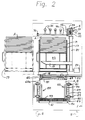
- Fig. 2 is a section along the line II-II in Fig. 1, and
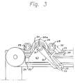
- Fig. 3 is a side view showing the device of Figs. 1 and 2 on an enlarged scale.
- the device according to the invention is built into a machine provided with a support 1 having wheels 2.
- the main parts of the machine are a device in the form of a platform 10, receiving a sheaf of papers B, the sheets of paper of which are not interconnected, from a copying machine (not shown) or a (laser) printer, a device 3, transporting the sheaf of papers to an assembly device 4, a device 5 for taking covers A out of a cassette K and transporting one cover at a time to the device 4, a device 6 for collecting covers containing sheaves of papers, which covers have been fed out from the assembly device 4, a device 7 for activation of a binding agent on the spine of each cover A, so as to connect the sheaf of papers in the cover with the spine thereof, a device 8 for jogging up the sheaves of papers in the covers in connection with their passing through the activation device 7, and a device 9 for carrying away booklets H comprising sheaves of papers B bound into the covers A.
- the transport device 3 for the sheaves of papers B includes a plate 12 which is insertable between the platform 10 and a sheaf of papers B resting thereon, the plate being mounted at 11a on an arm 1 mounted at 12 to which arm a reciprocating pivoting movement is imparted by a driving device (not shown). Said pivoting movement in one direction (clockwise) is indicated by the arrow P1. A reciprocating pivoting movement is imparted also to the plate 12 on the arm 11 by a driving device (not shown). Said pivoting movement in one direction (counter-clockwise) is indicated by the arrow P2.
- a holding means 15 to which is imparted, by a driving device (not shown), a pivoting movement between a position in which the holding means presses a sheaf of papers B lying on the plate 12 onto the same, as shown in solid lines in Fig. 1, and a position in which the holding means is at a distance from the sheaf of papers, as shown in dash dotted lines in Fig. 1.
- the sheaf of papers B usually consists of a sheaf of sheets of paper of the same size (A4) which are not interconnected. Further, the sheaf of papers B may contain so called index sheets having portions on which letters and/or numbers are printed, which portions project beyond the other sheets of the sheaf of papers.
- Fig. 2 there is shown a sheaf of this kind containing 10 index sheets B1 provided with numerals 1 - 10. As is evident from the figure, the index sheets B1 are designed such that no portions of the same project beyond the upper side edge of the sheaf of papers B in the two areas adjacent the two end edges of the sheaf of papers.
- Each of the covers A consists of a sheet of cardboard and/or plastics material provided with creasing lines along which the sheet is folded and which define two cover sheets and a spine therebetween.
- a binding agent usually consisting of a bead of glue of a thermoplastic material, which at room temperature is solid but will become plastic when heated.
- Each cassette K consists of a box of cardboard or the like which is closed during storage and transportation.
- the cassette is provided with weakenings (not shown) so that a portion of the cassette is easily removable to expose an opening K1, through which the covers A may be taken out of the cassette.
- the cassette K has an abutment K2 which, for example, is integral with the cassette and which centers the covers therein.
- the cassette K also contains a support means K3, preferably in the form of a cardboard wedge extending between two of the side walls of the cassette, which cardboard wedge is displaceable within the cassette obliquely upwards-downwards as shown in Fig. 1.
- An empty cassette K is filled with covers A by inserting a stack of covers, which bear against each other and form a V-shape, for example, through the base of the cassette, whereupon the wedge K3 is likewise inserted through the base and into the space in the innermost cover. The base is then closed.
- the outermost cover A bears against the abutment K2 and against a non-illustrated cap portion of the cassette, identical with the abutment, which portion will later be removed on opening of the cassette so as to form the opening K1.
- Said cover in turn bears against another cover such that the binding agent on the spine of the first-mentioned cover is located opposite and in contact with the outside of the spine of the last-mentioned cover or is located at a short distance therefrom.
- said portion and the wedge K3 it is ensured that the covers will be centered and that they will keep their V-shape in the cassette.
- each cassette is detachably inserted in a slider 16 and 17, respectively, which is easily slidable, by means of wheels 18 and expanding bars 22, from a position shown in dash-dotted lines in Fig. 2 outwardly of the machine support 1 to a position inside the machine as shown in solid lines in Figs. 1 and 2.
- a sword 19 disposed in the machine will penetrate one of the side walls of the cassette and will be inserted in the wedge K3 to the position shown in Fig. 2.
- the sword 19 will then be displaced upwards by a reversible motor 20 which is connected with the sword by means of a belt 21. Said displacement will cause the wedge K3 to be displaced upwards in the cassette carrying with it the covers A while the sword 19 is cutting a slot in the side wall of the cassette.
- the side wall may, for example, be perforated.
- the displacement of the sword, the wedge and the covers will continue until the spine portion of the uppermost (outermost) cover A acts on a photocell means (not shown) disposed above the cassette K which will give an impulse to the motor 20 to stop.
- the device 5 which is best shown in Fig. 3, includes a reciprocating endless conveyor belt 23 driven by a reversible motor (not shown). In the space between the upper and lower parts of the conveyor belt 23 there is a rail 24, a vertically slidable projection 25 and a fixed projection 26.
- a slider 27 is horizontally slidably mounted on the rail 24.
- the slider 27 carries a wheel 28. Between the wheel 28 and the shaft 28a, on which the wheel is rotatably mounted on the slider, acts a helical spring 30.
- the belt 23 passes over the wheel 28 and under two rolls 29 rotatably mounted on either side of the wheel in the slider 27.
- the shaft 28a supports a wheel 31.
- a wheel 32 is attached to the shaft 34.
- the wheels 31 and 32 are interconnected by means of an endless belt 33.
- the shaft 34 which is hollow, supports four hollow arms with suction cups 33.
- the end of shaft 34 which is not mounted in the slider 27 is rotatably mounted on the machine support 1, at 36.
- a vacuum source (not shown) is connected with the shaft at 36.
- the stop 25 may be moved from the position in Fig. 1 in order not to prevent the slider 27 from being moved to a position in which it is stopped by the projection 26 above the right-hand cassette K. Said movement takes place on an impulse from the machine or the machine operator when covers A are to collected from the right-hand cassette, which should be done when the left-hand cassette is empty or when covers of other size or kind are to be used instead of the covers in the left-hand cassette.
- the assembly device 4 comprises a holder or a gap having two side walls 38 and 39 opposing each other at an angle of approximately 45°.
- the bottom of the gap 38, 39 is defined by a roll 40 rotatable by a non-illustrated motor and having a shoulder 41 as well as by a counter roll 44 driven by a spring, which counter roll is freely rotatably towards the roll 40.
- the side walls 38 and 39 are provided with a fixed suction cup 42 and a movable suction cup 43, respectively, which are connected to a vacuum source (not shown).
- the roll 40 will then be rotated counter-clockwise, and the shoulder 41 will get out of contact with the spine of the cover A.
- the counter roll 44 will then be moved to the right in Fig. 1 and will clamp the cover A containing a sheaf of papers B against the periphery of the roll 40 above the shoulder 41.
- the cover and the sheaf of papers will be fed by said rolls in the direction of the arrow P4 and will fall down into the inclining collecting device 6.
- the device 6 comprises a shelf 46 mounted rotatably around the shaft 45, which shelf is able to support one or more covers A containing sheaves of papers B.
- the device 6 When the device 6 is pivoted clockwise round the shaft 45 to its vertical position shown in Fig. 1 in dash dotted lines, it will deliver the cover or several covers containing a sheaf (sheaves) of papers to the activation device 7.
- the activation device 7 comprises a transport device consisting of two identical, synchronously driven conveyors 50 each consisting of two identical cogged belts 51, which are interconnected by means of yokes 52. The smallest distance between the yokes of the two conveyors 50 is less than the height of a cover A.
- the two belts 51 in each conveyor 50 are driven by identical cogged wheels 53 which are interconnected by means of shafts 54.
- the lower ends of the shafts 54 are provided with bevel gear wheels 55 engaging bevel gear wheels 56 attached to a shaft 57, one of which being rotated by a motor (not shown).
- Each of the shafts 57 is provided with a roller 58. Round the rollers 58 extends an endless belt 59 whose speed is synchronous with the speeds of the conveyors 50. Between the two parts of the belts 59 there are disposed a heating means 60 and a cooling means 61.
- a cover A or several covers A containing a sheaf (sheaves) of papers B which are inserted by the device 6 between the conveyors 50, are collected by the yokes 52 and the belt 59.
- Fig. 2 there is shown a cover A containing a sheaf of papers B resting on the belt 59 and located between two pairs of opposing yokes 52.
- the distance between two adjacent yokes 52 in each conveyor 50 is selected such that there is room between them for several covers A of small spine width and containing sheaves of papers B or such that there is room between them for one cover of the largest spine width and containing a sheaf of papers.
- thermoplastic beads of glue on the inside of the spines are first heated by the device 60 so that the beads of glue will melt and the sheaves of papers will sink into the same.
- the bead of glue will be cooled by the device 61, whereby the beads of glue will solidify and the sheaves of papers B will be connected to the inside of the spines.
- the covers A containing the sheaves of papers B through the heating portion of the device 7, i.e. over the device 60 they will be jogged up by the device 8.
- the jogging up device 8 comprises a plate 62 having two lower side portions 62a, the distance between which is somewhat less than the height of a cover A and a sheaf of papers B and is somewhat greater than the portions of the index sheets B1 projecting beyond the edge of the sheaf of papers and the cover farthest away from the latter.
- the plate 62 is connected with two arms 63 mounted on the machine support 1 and is pivoted by a motor (not shown) between an upper position at a distance from the the covers and the sheaves of papers in the device 7 and a lower position in which the portions 62a press against the two areas of the covers and the sheaves of papers which are located on either side of the index sheets B1.
- the last-mentioned position is shown in Figs. 1 and 2.
- the extension of the plate 62 in the longitudinal direction of the device 7 is greater than the distance between a plurality of yokes 52 in order for several covers and sheaves of papers to be jogged up simultaneously every time the plate 62 is pivoted towards
- a second jogging-up device comprises two spaced apart plates 70 to which is imparted, by non-illustrated drive means, a repeated movement towards and from the vertical side edges of the covers A and the sheaves of papers B in Fig. 2 so as to ensure that they will be positioned in a respective vertical plane.
- the transport device 9 comprises two spaced apart endless conveyor belts 64 extending around two rollers 65 and 66, one of which is driven by a motor (not shown).
- the belts 64 are provided with a plurality of projecting, equally spaced apart shelves 67.
- a motor driven device 68 working synchronously with the belt 64 will convey the booklet(s) to an inclined plane 69 on the machine support. In said plane 69, the booklets are available to be removed from the machine.
Claims (18)
- Verfahren zur Herstellung von Broschüren, von denen jede einen aus zwei Umschlagseiten und einem dazwischen sich befindenden Rücken hergestellten Umschlag, und eine auf der Innenseite des Rückens aufgebrachte Klebstoffraupe, sowie ein zwischen die beiden Umschlagseiten des Umschlages eingeführtes Papierbündel, aufweist, wobei die eine Seitenkante dieses Bündels über die Klebstoffraupe mit der Rückeninnenseite verbunden ist, gekennzeichnet durch folgende Schritte:a) Transport eines aus nicht miteinander verbundenen Papierblättern bestehenden Papierbündels (B) mittels einer ersten motorangetriebenen Transportvorrichtung (3) in eine erste Position,b) Transport eines von mehreren mit angebrachter Klebstoffraupe versehener Umschläge (A), wobei diese Umschläge aneinander anliegend angeordnet sind, mittels der ersten Transportvorrichtung oder einer zweiten motorangetriebenen Transportvorrichtung (5) in eine von den anderen Umschlägen distanzierte zweite Position,c) in Kontakt bringen des Papierbündels mit dem mit der Klebstoffraupe versehenen Umschlag, derart, dass das Papierbündel im Umschlag umschlossen wird und die Seitenkante des Papierbündels gegen die Klebstoffraupe zu gerichtet ist, undd) Transport des ein Papierbündel enthaltenden Umschlages an einer Aktivierungseinheit (7) vorbei, oder umgekehrt, wobei diese Aktivierungseinheit die Klebstoffraupe derart aktiviert, dass die Seitenkante des Papierbündels mit der Innenseite des Rückens verbunden wird.
- Verfahren nach Anspruch 1, dadurch gekennzeichnet, dass das Papierbündel (B) aus einer Kopiermaschine oder einem Laserdrucker in eine von dieser bzw. diesem distanzierte Position zugeführt wird, wo das Papierbündel zum Transport verfügbar ist.
- Verfahren nach Anspruch 1 oder 2, dadurch gekennzeichnet, dass die Klebstoffraupe durch Erwärmen derselben bis sie mindestens teilweise schmilzt, aktiviert, und danach durch Abkühlung erhärtet wird.
- Verfahren nach einem der vorangehenden Ansprüche, dadurch gekennzeichnet, dass der Umschlag (A) in eine Position (bei 4) transportiert wird, in welcher seine Umschlagseiten voneinander distanziert sind, das Papierbündel (B) in eine Position innerhalb dem Umschlag transportiert wird, die Umschlagseiten gegeneinander zu bewegt werden bis sie im wesentlichen parallel zueinander verlaufen, und während dem Transport des Umschlags und des Papierbündels relativ zur Aktivierungseinheit (7) in dieser Position gehalten werden.
- Verfahren nach einem der vorangehenden Ansprüche, dadurch gekennzeichnet, dass der ein Papierbündel (B) enthaltende Umschlag (A) in eine Warteposition (bei 6) transportiert wird bevor er allein oder zusammen mit weiteren in der Warteposition sich befindenden, Papierbündel enthaltenden Umschlägen mittels einer Transportvorrichtung (50-59) an der Aktiviereinheit (7), oder umgekehrt, vorbeibewegt wird.
- Verfahren nach einem der vorangehenden Ansprüche, dadurch gekennzeichnet, dass das Papierbündel (B) nach dem Zusammenfügen mit dem Umschlag (A) aufgestossen wird.
- Verfahren nach einem der vorangehenden Ansprüche, dadurch gekennzeichnet, dass eine Mehrzahl von mit Klebstoffraupen versehenen Umschlägen (A) einzeln aus einer Kassette (K) abgegeben wird, wobei die Umschläge (A) unter weitgehend gleichen Abständen voneinander gehalten werden, worauf sie mittels der zweiten Transportvorrichtung (5) weitertransportiert werden.
- Verfahren nach Anspruch 7, dadurch gekennzeichnet, dass, nachdem ein oder mehrere Umschläge aus der Kassette (K) abgegeben wurden, die nachfolgenden Umschlage in im wesentlichen die gleiche Position wie der bzw. die zuerst erwähnte(n) Umschlag bzw. Umschläge sich befand(en) als er bzw. sie aus der Kassette abgegeben wurden, transportiert werden.
- Verfahren nach einem der vorangehenden Ansprüche, dadurch gekennzeichnet, dass sämtliche Umschläge (A) mittels einer Transportvorrichtung (19-21) direkt oder über eine für die Umschläge bestimmte Abstützanordnung (K3) transportiert werden.
- Vorrichtung zur Herstellung von Broschüren, von denen jede einen aus zwei Umschlagseiten und einem dazwischen sich befindenden Rücken hergestellten Umschlag, und eine auf der Innenseite des Rückens aufgebrachte Klebstoffraupe, sowie ein zwischen die beiden Umschlagseiten des Umschlages eingeführtes Papierbündel, aufweist, wobei die eine Seitenkante dieses Bündels über die Klebstoffraupe mit der Rückeninnenseite verbunden ist, gekennzeichnet durcha) eine erste motorangetriebene Transportvorrichtung (3) zum Transport eines Papierbündels (B), bestehend aus nicht miteinander verbundenen Papierblättern in eine erste Position,b) eine zweite motorangetriebene Transportvorrichtung (5) zum Transport eines mit angebrachter Klebstoffraupe versehenen Umschlages (A) in eine von einer Mehrzahl von mit Klebstoffraupen versehenen, aneinanderliegenden Umschlägen distanzierte zweite Position,c) eine Zusammenführanordnung (4) zum Zusammenbringen des Papierbündels mit dem mit der Klebstoffraupe versehenen Umschlag,d) eine Transportvorrichtung (50-59) zur Aufnahme des mit der Klebstoffraupe und dem Papierbündel versehenen Umschlages, wobei die Seitenkante des Papierbündels an der Klebstoffraupe anliegt, unde) eine Aktivierungseinheit (7) zur Aktivierung der Klebstoffraupe während der Bewegung der Transportvorrichtung oder der Aktivierungseinheit, so dass die Seitenkante des Papierbündels mit der Innenseite des Rückens verbunden wird.
- Vorrichtung nach Anspruch 10, dadurch gekennzeichnet, dass die Aktivierungseinheit (7) eine Heizanordnung (60) und in Transportrichtung der Umschläge gesehen nach der Heizanordnung vorzugsweise eine Kühlanordnung (61) aufweist.
- Vorrichtung nach Anspruch 10 oder 11, dadurch gekennzeichnet, dass die zweite motorangetriebene Transportvorrichtung (5) mindestens eine sich hin- und herbewegende Ansaugvorrichtung (35) aufweist.
- Vorrichtung nach einem der Ansprüche 10-12, dadurch gekennzeichnet, dass die Zusammenführanordnung (4) einen Halter (38,39), in welchem ein Umschlag (A) während dem Einführen eines Papierbündels in denselben mit den Umschlagseiten vorzugsweise einen spitzen Winkel bildend, gehalten wird, und Mittel (40,41,42) zum Transport des ein Papierbündel enthaltenden Umschlages gegen eine Aktivierungseinheit (7) zu, aufweist.
- Vorrichtung nach einem der Ansprüche 10-13, gekennzeichnet durch eine Sammelanordnung (6) für mehrere, Papierbündel (B) enthaltende Umschläge (A), wobei diese Sammelanordnung zum Transport eines oder mehrerer je ein Papierbündel enthaltender Umschläge zur Transportvorrichtung (50-59) bestätigtwerden kann.
- Vorrichtung nach einem der Ansprüche 10-14, gekennzeichnet durch eine Aufstossanordnung (8) zum Aufstossen des Papierbündels (B) nach dessen Zusammenfügen mit dem mit einer Klebstoffraupe versehenen Umschlag (A).
- Vorrichtung nach einem der Ansprüche 10-15, dadurch gekennzeichnet, dass die Umschläge in einer Kassette (k) zusammengebracht und mittels einer Anordnung (19-21) zum Transport der Umschläge zu der zweiten Transportvorrichtung (5) aus der Kassette ausgebracht werden.
- Vorrichtung nach Anspruch 16, dadurch gekennzeichnet, dass die Transferanordnung (19-21) ein Element (19) aufweist, welches sich in Kontakt mit mindestens einem der in der Kassette sich befindenden Umschläge (A) befindet oder mit einem Abstand von den in der Kassette (K) sich befindenden Umschlägen angeordnet ist, wobei dieser Abstand mittels einer für die Umschläge (A) bestimmten Abstützanordnung (K3) überbrückt wird.
- Vorrichtung nach Anspruch 16 oder 17, dadurch gekennzeichnet, dass die Transferanordnung (19-21) zum Transport der in der Kassette (K) sich befindenden Umschläge (A) über einen in der Kassette (K) sich befindenden Schlitz ausgebildet ist.
Priority Applications (2)
| Application Number | Priority Date | Filing Date | Title |
|---|---|---|---|
| EP97109109A EP0798245B1 (de) | 1993-05-18 | 1994-05-17 | Kassette für Broschüren-Einbanddeckel und Verfahren zum Füllen derselben |
| GR20000401720T GR3034029T3 (en) | 1993-05-18 | 2000-07-26 | A cassette containing booklet covers and a method for filling the same |
Applications Claiming Priority (3)
| Application Number | Priority Date | Filing Date | Title |
|---|---|---|---|
| SE19939301708A SE9301708D0 (sv) | 1993-05-18 | 1993-05-18 | Saett och anordning foer att tilverka haeften |
| SE9301708 | 1993-05-18 | ||
| PCT/SE1994/000460 WO1994026535A1 (en) | 1993-05-18 | 1994-05-17 | A method and a device for the manufacture of booklets |
Related Child Applications (1)
| Application Number | Title | Priority Date | Filing Date |
|---|---|---|---|
| EP97109109A Division EP0798245B1 (de) | 1993-05-18 | 1994-05-17 | Kassette für Broschüren-Einbanddeckel und Verfahren zum Füllen derselben |
Publications (2)
| Publication Number | Publication Date |
|---|---|
| EP0703867A1 EP0703867A1 (de) | 1996-04-03 |
| EP0703867B1 true EP0703867B1 (de) | 1998-01-21 |
Family
ID=20389982
Family Applications (2)
| Application Number | Title | Priority Date | Filing Date |
|---|---|---|---|
| EP97109109A Expired - Lifetime EP0798245B1 (de) | 1993-05-18 | 1994-05-17 | Kassette für Broschüren-Einbanddeckel und Verfahren zum Füllen derselben |
| EP94916463A Expired - Lifetime EP0703867B1 (de) | 1993-05-18 | 1994-05-17 | Vorrichtung und verfahren zum herstellen von broschüren |
Family Applications Before (1)
| Application Number | Title | Priority Date | Filing Date |
|---|---|---|---|
| EP97109109A Expired - Lifetime EP0798245B1 (de) | 1993-05-18 | 1994-05-17 | Kassette für Broschüren-Einbanddeckel und Verfahren zum Füllen derselben |
Country Status (15)
| Country | Link |
|---|---|
| US (1) | US5570985A (de) |
| EP (2) | EP0798245B1 (de) |
| JP (1) | JP3611328B2 (de) |
| KR (1) | KR100323726B1 (de) |
| AT (2) | ATE192116T1 (de) |
| AU (1) | AU686164B2 (de) |
| CA (1) | CA2161699C (de) |
| DE (2) | DE69424191T2 (de) |
| ES (2) | ES2114197T3 (de) |
| GR (2) | GR3026685T3 (de) |
| NO (2) | NO306542B1 (de) |
| SE (1) | SE9301708D0 (de) |
| TW (1) | TW235942B (de) |
| WO (1) | WO1994026535A1 (de) |
| ZA (1) | ZA943431B (de) |
Families Citing this family (14)
| Publication number | Priority date | Publication date | Assignee | Title |
|---|---|---|---|---|
| SE9301708D0 (sv) * | 1993-05-18 | 1993-05-18 | Jan Sabelstroem | Saett och anordning foer att tilverka haeften |
| IT1261356B (it) * | 1993-11-18 | 1996-05-20 | Finlega Spa | Procedimento e macchina per la fabbricazione di copertine per libri e simili, e copertine cosi' realizzate. |
| SE506022C2 (sv) * | 1996-01-22 | 1997-11-03 | Urpo Latvakangas | Förfarande, anordning och tillbehör för framställning av häften |
| SE506217C2 (sv) * | 1996-03-14 | 1997-11-24 | Urpo Latvakangas | Förfarande och anordning för att tillverka häften |
| SE507804C2 (sv) * | 1996-11-11 | 1998-07-13 | Bindomatic Ab | Sätt att stapla för framställning av häften avsedda höljen, ett dylikt hölje och sätt vid tillverkning av dylika häften |
| JPH10147465A (ja) * | 1996-11-20 | 1998-06-02 | Minolta Co Ltd | 用紙処理装置 |
| US6213456B1 (en) * | 1997-01-08 | 2001-04-10 | Minolta Co., Ltd. | Finisher for use with an image forming apparatus |
| US6042318A (en) * | 1997-06-30 | 2000-03-28 | Xerox Corporation | Bookbinding system employing microwave heating |
| EP0999074B1 (de) * | 1998-11-02 | 2006-02-01 | Grapha-Holding Ag | Verfahren zur Herstellung von Druckerzeugnissen |
| JP3744234B2 (ja) * | 1998-11-10 | 2006-02-08 | コニカミノルタホールディングス株式会社 | シート後処理装置及び画像形成装置 |
| US6494661B1 (en) * | 2000-05-12 | 2002-12-17 | Heidelberger Druckmaschinen Ag | Device and method for providing a cover for a book |
| US6893874B2 (en) * | 2000-10-17 | 2005-05-17 | Baker Hughes Incorporated | Method for storing and transporting crude oil |
| US7185646B2 (en) | 2003-10-27 | 2007-03-06 | Smart Parts, Inc. | Pneumatic assembly for a paintball gun |
| CN114347557A (zh) * | 2022-01-10 | 2022-04-15 | 广东晟图智能装备有限公司 | 全自动皮壳包边设备 |
Family Cites Families (28)
| Publication number | Priority date | Publication date | Assignee | Title |
|---|---|---|---|---|
| US936480A (en) * | 1908-01-08 | 1909-10-12 | George Sague | Pamphlet-coverer. |
| US2549890A (en) * | 1946-07-03 | 1951-04-24 | Hoe & Co R | Book casing-in machine |
| US3093396A (en) * | 1960-12-22 | 1963-06-11 | Betsy Ross Feld | Bookbinding method and apparatus |
| GB1258746A (de) * | 1969-03-17 | 1971-12-30 | ||
| CH541436A (de) * | 1970-05-14 | 1973-09-15 | Hunkeler Ag Jos | Vorrichtung zum Einschieben und Einkleben von Einlageblättern in Papierbogen |
| CH513729A (de) * | 1970-10-15 | 1971-10-15 | Martini Buchbindermaschf | Vorrichtung an Heftmaschine zum Zuführen und Ausrichten von gefalzten Bogenlagen |
| US3767188A (en) * | 1971-05-24 | 1973-10-23 | Burt & Co F N | Paper feeding device |
| NL145364B (nl) * | 1971-06-17 | 1975-03-17 | Optische Ind De Oude Delft Nv | Inrichting voor het een voor een verplaatsen van rechthoekige stukken bladvormig materiaal van een stapel. |
| US3952356A (en) * | 1975-02-21 | 1976-04-27 | Minnesota Mining & Manufacturing Company | Gauge and alignment device for attaching covers to books |
| US3994427A (en) * | 1975-04-29 | 1976-11-30 | Pitney-Bowes, Inc. | Automatic sheet jogging and stapling machine |
| CH610547A5 (de) * | 1975-05-12 | 1979-04-30 | Gen Binding Corp | |
| DE2614530A1 (de) * | 1976-04-03 | 1977-10-13 | Eisbein Develop | Verpackungsmittel fuer einen blattstapel |
| US4178201A (en) * | 1976-04-27 | 1979-12-11 | Swingline, Inc. | Carrier for holding sheets of material for use with a thermal binding machine |
| SE422044B (sv) * | 1979-10-25 | 1982-02-15 | Asteroe & Stockhaus | Anordning for jemnstotning av en arkbunt |
| SE434367B (sv) * | 1980-04-15 | 1984-07-23 | Semotex Ab | Bindningsanordning |
| US4381108A (en) * | 1981-06-29 | 1983-04-26 | Newsome John R | Device for aligning signatures fed in shingled relation |
| FR2540788B3 (fr) * | 1983-02-15 | 1985-12-13 | Ordibel | Ensemble d'emboitage, de transfert et d'empilage, a fonctionnement automatique, pour machines a brocher des documents |
| IT1175477B (it) * | 1984-04-09 | 1987-07-01 | Sitma | Caricatore di segnatura fogli e prodotti similari per alimentatori di macchine confezionatrici di macchine per legatoria e simili |
| SE444538B (sv) * | 1984-09-19 | 1986-04-21 | Bind O Matic Ab | Anordning for limning av ark |
| JPS61133366U (de) * | 1985-02-07 | 1986-08-20 | ||
| US4626156A (en) * | 1985-05-13 | 1986-12-02 | Eastman Kodak Company | Finishing apparatus with cover inserter |
| JPS6265260U (de) * | 1985-10-14 | 1987-04-23 | ||
| DE3614216C2 (de) * | 1986-04-26 | 1994-08-11 | Kolbus Gmbh & Co Kg | Buchdeckenmagazin für Bucheinhängemaschine |
| SE500756C2 (sv) * | 1989-09-15 | 1994-08-29 | Jan Tholerus | Sätt och maskin för tillverkning av häften |
| SE8903049L (sv) * | 1989-09-15 | 1991-03-16 | Jan Tholerus | Anordning vid tillverkning av hoeljen |
| JPH03106695A (ja) * | 1989-09-21 | 1991-05-07 | Mita Ind Co Ltd | 製本機 |
| JPH0785948B2 (ja) * | 1991-01-08 | 1995-09-20 | 隆治 宮崎 | 丁合機の自動給紙装置 |
| SE9301708D0 (sv) * | 1993-05-18 | 1993-05-18 | Jan Sabelstroem | Saett och anordning foer att tilverka haeften |
-
1993
- 1993-05-18 SE SE19939301708A patent/SE9301708D0/xx unknown
-
1994
- 1994-04-08 US US08/224,809 patent/US5570985A/en not_active Expired - Lifetime
- 1994-05-16 TW TW083104408A patent/TW235942B/zh not_active IP Right Cessation
- 1994-05-17 AT AT97109109T patent/ATE192116T1/de not_active IP Right Cessation
- 1994-05-17 ES ES94916463T patent/ES2114197T3/es not_active Expired - Lifetime
- 1994-05-17 KR KR1019950705143A patent/KR100323726B1/ko not_active IP Right Cessation
- 1994-05-17 DE DE69424191T patent/DE69424191T2/de not_active Expired - Fee Related
- 1994-05-17 WO PCT/SE1994/000460 patent/WO1994026535A1/en active IP Right Grant
- 1994-05-17 AT AT94916463T patent/ATE162472T1/de not_active IP Right Cessation
- 1994-05-17 EP EP97109109A patent/EP0798245B1/de not_active Expired - Lifetime
- 1994-05-17 EP EP94916463A patent/EP0703867B1/de not_active Expired - Lifetime
- 1994-05-17 DE DE69408139T patent/DE69408139T2/de not_active Expired - Fee Related
- 1994-05-17 CA CA002161699A patent/CA2161699C/en not_active Expired - Fee Related
- 1994-05-17 AU AU68109/94A patent/AU686164B2/en not_active Ceased
- 1994-05-17 JP JP52534094A patent/JP3611328B2/ja not_active Expired - Lifetime
- 1994-05-17 ES ES97109109T patent/ES2148875T3/es not_active Expired - Lifetime
- 1994-05-18 ZA ZA943431A patent/ZA943431B/xx unknown
-
1995
- 1995-11-15 NO NO954610A patent/NO306542B1/no not_active IP Right Cessation
-
1998
- 1998-04-21 GR GR980400866T patent/GR3026685T3/el unknown
-
1999
- 1999-07-26 NO NO19993625A patent/NO323339B1/no not_active IP Right Cessation
-
2000
- 2000-07-26 GR GR20000401720T patent/GR3034029T3/el not_active IP Right Cessation
Also Published As
| Publication number | Publication date |
|---|---|
| NO323339B1 (no) | 2007-04-02 |
| TW235942B (de) | 1994-12-11 |
| WO1994026535A1 (en) | 1994-11-24 |
| DE69424191T2 (de) | 2001-02-15 |
| DE69408139D1 (de) | 1998-02-26 |
| EP0798245A2 (de) | 1997-10-01 |
| GR3026685T3 (en) | 1998-07-31 |
| AU686164B2 (en) | 1998-02-05 |
| US5570985A (en) | 1996-11-05 |
| NO954610L (no) | 1995-11-15 |
| JP3611328B2 (ja) | 2005-01-19 |
| ES2114197T3 (es) | 1998-05-16 |
| DE69424191D1 (de) | 2000-05-31 |
| KR960702387A (ko) | 1996-04-27 |
| SE9301708D0 (sv) | 1993-05-18 |
| CA2161699A1 (en) | 1994-11-24 |
| GR3034029T3 (en) | 2000-11-30 |
| NO993625L (no) | 1995-11-15 |
| KR100323726B1 (ko) | 2002-06-20 |
| DE69408139T2 (de) | 1998-09-03 |
| NO306542B1 (no) | 1999-11-22 |
| CA2161699C (en) | 2005-04-12 |
| EP0703867A1 (de) | 1996-04-03 |
| ZA943431B (en) | 1995-02-17 |
| EP0798245B1 (de) | 2000-04-26 |
| ATE162472T1 (de) | 1998-02-15 |
| ES2148875T3 (es) | 2000-10-16 |
| AU6810994A (en) | 1994-12-12 |
| NO954610D0 (no) | 1995-11-15 |
| ATE192116T1 (de) | 2000-05-15 |
| JPH08510200A (ja) | 1996-10-29 |
| EP0798245A3 (de) | 1997-12-17 |
| NO993625D0 (no) | 1999-07-26 |
Similar Documents
| Publication | Publication Date | Title |
|---|---|---|
| AU723328B2 (en) | Method, device and accessories for the manufacture of booklets | |
| EP0703867B1 (de) | Vorrichtung und verfahren zum herstellen von broschüren | |
| CN1107617C (zh) | 用于生产包装件的设备 | |
| US6837290B2 (en) | Informational item bonding machine | |
| EP0685328B1 (de) | Stauchfalzmaschine | |
| EP0491825B1 (de) | Verfahren und vorrichtung zur herstellung von broschüren | |
| CA2271383C (en) | A cover intended for the fabrication of a booklet, a method of handling such covers, and a method of fabricating such booklets | |
| AU706082B2 (en) | A cassette containing booklet covers and a method for filling the same | |
| JP2992568B2 (ja) | テープによる結束装置 | |
| CA2243561C (en) | Method, device and accessories for the manufacture of booklets | |
| US4855010A (en) | Apparatus for gluing sheets of material together | |
| EP0572459A1 (de) | Verfahren zur automatischen verpackung von photographische bildern und vorrichtung zur ausführung des verfahrens | |
| MXPA99004263A (en) | A cover intended for the fabrication of a booklet, a method of handling such covers, and a method of fabricating such booklets | |
| JPH02196677A (ja) | 紙片搬送装置付きプリンタ |
Legal Events
| Date | Code | Title | Description |
|---|---|---|---|
| PUAI | Public reference made under article 153(3) epc to a published international application that has entered the european phase |
Free format text: ORIGINAL CODE: 0009012 |
|
| 17P | Request for examination filed |
Effective date: 19951218 |
|
| AK | Designated contracting states |
Kind code of ref document: A1 Designated state(s): AT BE CH DE DK ES FR GB GR IE IT LI LU MC NL PT SE |
|
| 17Q | First examination report despatched |
Effective date: 19960729 |
|
| GRAG | Despatch of communication of intention to grant |
Free format text: ORIGINAL CODE: EPIDOS AGRA |
|
| GRAG | Despatch of communication of intention to grant |
Free format text: ORIGINAL CODE: EPIDOS AGRA |
|
| GRAH | Despatch of communication of intention to grant a patent |
Free format text: ORIGINAL CODE: EPIDOS IGRA |
|
| GRAH | Despatch of communication of intention to grant a patent |
Free format text: ORIGINAL CODE: EPIDOS IGRA |
|
| GRAA | (expected) grant |
Free format text: ORIGINAL CODE: 0009210 |
|
| RAP1 | Party data changed (applicant data changed or rights of an application transferred) |
Owner name: BINDOMATIC AB |
|
| RIN1 | Information on inventor provided before grant (corrected) |
Inventor name: SABELSTROEM, JAN Inventor name: LATVAKANGAS, URPO |
|
| AK | Designated contracting states |
Kind code of ref document: B1 Designated state(s): AT BE CH DE DK ES FR GB GR IE IT LI LU MC NL PT SE |
|
| PG25 | Lapsed in a contracting state [announced via postgrant information from national office to epo] |
Ref country code: AT Free format text: LAPSE BECAUSE OF FAILURE TO SUBMIT A TRANSLATION OF THE DESCRIPTION OR TO PAY THE FEE WITHIN THE PRESCRIBED TIME-LIMIT Effective date: 19980121 |
|
| REF | Corresponds to: |
Ref document number: 162472 Country of ref document: AT Date of ref document: 19980215 Kind code of ref document: T |
|
| XX | Miscellaneous (additional remarks) |
Free format text: TEILANMELDUNG 97109109.5 EINGEREICHT AM 05/06/97. |
|
| REG | Reference to a national code |
Ref country code: CH Ref legal event code: EP |
|
| REF | Corresponds to: |
Ref document number: 69408139 Country of ref document: DE Date of ref document: 19980226 |
|
| ITF | It: translation for a ep patent filed |
Owner name: JACOBACCI & PERANI S.P.A. |
|
| PG25 | Lapsed in a contracting state [announced via postgrant information from national office to epo] |
Ref country code: PT Free format text: LAPSE BECAUSE OF FAILURE TO SUBMIT A TRANSLATION OF THE DESCRIPTION OR TO PAY THE FEE WITHIN THE PRESCRIBED TIME-LIMIT Effective date: 19980421 Ref country code: DK Free format text: LAPSE BECAUSE OF FAILURE TO SUBMIT A TRANSLATION OF THE DESCRIPTION OR TO PAY THE FEE WITHIN THE PRESCRIBED TIME-LIMIT Effective date: 19980421 |
|
| REG | Reference to a national code |
Ref country code: ES Ref legal event code: FG2A Ref document number: 2114197 Country of ref document: ES Kind code of ref document: T3 |
|
| PG25 | Lapsed in a contracting state [announced via postgrant information from national office to epo] |
Ref country code: LU Free format text: LAPSE BECAUSE OF NON-PAYMENT OF DUE FEES Effective date: 19980517 Ref country code: IE Free format text: LAPSE BECAUSE OF NON-PAYMENT OF DUE FEES Effective date: 19980517 |
|
| ET | Fr: translation filed | ||
| REG | Reference to a national code |
Ref country code: IE Ref legal event code: FG4D Free format text: 78588 |
|
| PLBQ | Unpublished change to opponent data |
Free format text: ORIGINAL CODE: EPIDOS OPPO |
|
| PLBI | Opposition filed |
Free format text: ORIGINAL CODE: 0009260 |
|
| PLBF | Reply of patent proprietor to notice(s) of opposition |
Free format text: ORIGINAL CODE: EPIDOS OBSO |
|
| PG25 | Lapsed in a contracting state [announced via postgrant information from national office to epo] |
Ref country code: MC Free format text: LAPSE BECAUSE OF NON-PAYMENT OF DUE FEES Effective date: 19981130 |
|
| 26 | Opposition filed |
Opponent name: SWEDEX VERTIEBS-GMBH FUER TECHNISCHE UND ELEKTROTE Effective date: 19981020 |
|
| NLR1 | Nl: opposition has been filed with the epo |
Opponent name: SWEDEX VERTIEBS-GMBH FUER TECHNISCHE UND ELEKTROTE |
|
| PLBF | Reply of patent proprietor to notice(s) of opposition |
Free format text: ORIGINAL CODE: EPIDOS OBSO |
|
| REG | Reference to a national code |
Ref country code: IE Ref legal event code: MM4A |
|
| PLBO | Opposition rejected |
Free format text: ORIGINAL CODE: EPIDOS REJO |
|
| REG | Reference to a national code |
Ref country code: GB Ref legal event code: IF02 |
|
| PLBN | Opposition rejected |
Free format text: ORIGINAL CODE: 0009273 |
|
| STAA | Information on the status of an ep patent application or granted ep patent |
Free format text: STATUS: OPPOSITION REJECTED |
|
| 27O | Opposition rejected |
Effective date: 20011007 |
|
| NLR2 | Nl: decision of opposition | ||
| PGFP | Annual fee paid to national office [announced via postgrant information from national office to epo] |
Ref country code: GR Payment date: 20040525 Year of fee payment: 11 |
|
| PG25 | Lapsed in a contracting state [announced via postgrant information from national office to epo] |
Ref country code: GR Free format text: LAPSE BECAUSE OF NON-PAYMENT OF DUE FEES Effective date: 20051205 |
|
| PLAB | Opposition data, opponent's data or that of the opponent's representative modified |
Free format text: ORIGINAL CODE: 0009299OPPO |
|
| PGFP | Annual fee paid to national office [announced via postgrant information from national office to epo] |
Ref country code: NL Payment date: 20090527 Year of fee payment: 16 Ref country code: ES Payment date: 20090525 Year of fee payment: 16 |
|
| PGFP | Annual fee paid to national office [announced via postgrant information from national office to epo] |
Ref country code: SE Payment date: 20090525 Year of fee payment: 16 Ref country code: IT Payment date: 20090530 Year of fee payment: 16 Ref country code: FR Payment date: 20090529 Year of fee payment: 16 Ref country code: DE Payment date: 20090526 Year of fee payment: 16 |
|
| PGFP | Annual fee paid to national office [announced via postgrant information from national office to epo] |
Ref country code: BE Payment date: 20090525 Year of fee payment: 16 |
|
| PGFP | Annual fee paid to national office [announced via postgrant information from national office to epo] |
Ref country code: CH Payment date: 20090515 Year of fee payment: 16 |
|
| PGFP | Annual fee paid to national office [announced via postgrant information from national office to epo] |
Ref country code: GB Payment date: 20090528 Year of fee payment: 16 |
|
| BERE | Be: lapsed |
Owner name: *BINDOMATIC A.B. Effective date: 20100531 |
|
| REG | Reference to a national code |
Ref country code: NL Ref legal event code: V1 Effective date: 20101201 |
|
| REG | Reference to a national code |
Ref country code: CH Ref legal event code: PL |
|
| GBPC | Gb: european patent ceased through non-payment of renewal fee |
Effective date: 20100517 |
|
| EUG | Se: european patent has lapsed | ||
| REG | Reference to a national code |
Ref country code: FR Ref legal event code: ST Effective date: 20110131 |
|
| PG25 | Lapsed in a contracting state [announced via postgrant information from national office to epo] |
Ref country code: LI Free format text: LAPSE BECAUSE OF NON-PAYMENT OF DUE FEES Effective date: 20100531 Ref country code: CH Free format text: LAPSE BECAUSE OF NON-PAYMENT OF DUE FEES Effective date: 20100531 |
|
| PG25 | Lapsed in a contracting state [announced via postgrant information from national office to epo] |
Ref country code: BE Free format text: LAPSE BECAUSE OF NON-PAYMENT OF DUE FEES Effective date: 20100531 Ref country code: SE Free format text: LAPSE BECAUSE OF NON-PAYMENT OF DUE FEES Effective date: 20100518 Ref country code: NL Free format text: LAPSE BECAUSE OF NON-PAYMENT OF DUE FEES Effective date: 20101201 Ref country code: IT Free format text: LAPSE BECAUSE OF NON-PAYMENT OF DUE FEES Effective date: 20100517 |
|
| PG25 | Lapsed in a contracting state [announced via postgrant information from national office to epo] |
Ref country code: DE Free format text: LAPSE BECAUSE OF NON-PAYMENT OF DUE FEES Effective date: 20101201 |
|
| PG25 | Lapsed in a contracting state [announced via postgrant information from national office to epo] |
Ref country code: FR Free format text: LAPSE BECAUSE OF NON-PAYMENT OF DUE FEES Effective date: 20100531 |
|
| REG | Reference to a national code |
Ref country code: ES Ref legal event code: FD2A Effective date: 20110715 |
|
| PG25 | Lapsed in a contracting state [announced via postgrant information from national office to epo] |
Ref country code: ES Free format text: LAPSE BECAUSE OF NON-PAYMENT OF DUE FEES Effective date: 20110705 Ref country code: GB Free format text: LAPSE BECAUSE OF NON-PAYMENT OF DUE FEES Effective date: 20100517 |
|
| PG25 | Lapsed in a contracting state [announced via postgrant information from national office to epo] |
Ref country code: ES Free format text: LAPSE BECAUSE OF NON-PAYMENT OF DUE FEES Effective date: 20100518 |