EP0703459A1 - Capteur d'accélération de type capacitif - Google Patents
Capteur d'accélération de type capacitif Download PDFInfo
- Publication number
- EP0703459A1 EP0703459A1 EP95113187A EP95113187A EP0703459A1 EP 0703459 A1 EP0703459 A1 EP 0703459A1 EP 95113187 A EP95113187 A EP 95113187A EP 95113187 A EP95113187 A EP 95113187A EP 0703459 A1 EP0703459 A1 EP 0703459A1
- Authority
- EP
- European Patent Office
- Prior art keywords
- capacitance
- capacitor
- acceleration
- difference
- acceleration sensor
- Prior art date
- Legal status (The legal status is an assumption and is not a legal conclusion. Google has not performed a legal analysis and makes no representation as to the accuracy of the status listed.)
- Granted
Links
Images


Classifications
-
- G—PHYSICS
- G01—MEASURING; TESTING
- G01P—MEASURING LINEAR OR ANGULAR SPEED, ACCELERATION, DECELERATION, OR SHOCK; INDICATING PRESENCE, ABSENCE, OR DIRECTION, OF MOVEMENT
- G01P15/00—Measuring acceleration; Measuring deceleration; Measuring shock, i.e. sudden change of acceleration
- G01P15/02—Measuring acceleration; Measuring deceleration; Measuring shock, i.e. sudden change of acceleration by making use of inertia forces using solid seismic masses
- G01P15/08—Measuring acceleration; Measuring deceleration; Measuring shock, i.e. sudden change of acceleration by making use of inertia forces using solid seismic masses with conversion into electric or magnetic values
- G01P15/13—Measuring acceleration; Measuring deceleration; Measuring shock, i.e. sudden change of acceleration by making use of inertia forces using solid seismic masses with conversion into electric or magnetic values by measuring the force required to restore a proofmass subjected to inertial forces to a null position
- G01P15/131—Measuring acceleration; Measuring deceleration; Measuring shock, i.e. sudden change of acceleration by making use of inertia forces using solid seismic masses with conversion into electric or magnetic values by measuring the force required to restore a proofmass subjected to inertial forces to a null position with electrostatic counterbalancing means
-
- G—PHYSICS
- G01—MEASURING; TESTING
- G01P—MEASURING LINEAR OR ANGULAR SPEED, ACCELERATION, DECELERATION, OR SHOCK; INDICATING PRESENCE, ABSENCE, OR DIRECTION, OF MOVEMENT
- G01P15/00—Measuring acceleration; Measuring deceleration; Measuring shock, i.e. sudden change of acceleration
- G01P15/02—Measuring acceleration; Measuring deceleration; Measuring shock, i.e. sudden change of acceleration by making use of inertia forces using solid seismic masses
- G01P15/08—Measuring acceleration; Measuring deceleration; Measuring shock, i.e. sudden change of acceleration by making use of inertia forces using solid seismic masses with conversion into electric or magnetic values
- G01P15/125—Measuring acceleration; Measuring deceleration; Measuring shock, i.e. sudden change of acceleration by making use of inertia forces using solid seismic masses with conversion into electric or magnetic values by capacitive pick-up
Definitions
- the present invention relates to a capacitor type acceleration sensor based on the electrostatic servo system for sensing an acceleration by making use of a variation of capacitance of a capacitor.
- a capacitor type acceleration sensor based on the electrostatic servo system is a typical example of the acceleration sensor.
- the capacitor type acceleration sensor is fabricated by a silicon microfabrication technique.
- the capacitor type acceleration sensor has a broad dynamic range and a high sensitivity. Because of advantageous features, the acceleration sensor has the attraction of designers in this field.
- Fig. 4 is a block diagram showing the circuit arrangement of a conventional capacitor type acceleration sensor based on the electrostatic servo system.
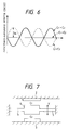
- the mechanical construction of an acceleration sensing element 1 used in the acceleration sensor of Fig. 4 is schematically illustrated in Fig. 7.
- a movable electrode 4 is disposed at the mid position (neutral position) between fixed electrodes 2 and 3.
- the movable electrode 4 is supported at both ends thereof by a couple of cantilevers 5 in such a way when receiving an acceleration, the movable electrode 4 is displaced in the Y directions.
- a variable capacitor C1 is constructed with the fixed electrode 2 and the movable electrode 4
- another variable capacitor C2 is constructed with the fixed electrode 3 and the movable electrode 4.
- the variable capacitors C1 and C2 are fabricated by the silicon microfabrication technique.
- a sinusoidal wave signal of an amplitude Vp and at an angular frequency ⁇ , generated by an oscillator 6, is applied to the variable capacitor C2 of the acceleration sensing element 1.
- a phase invertor 9 is inserted between the oscillator 6 and the variable capacitor C1.
- the sinusoidal wave signal, generated by the oscillator 6, is phase shifted by 180° by the phase invertor 9, and applied to the variable capacitor C1.
- the amplitude and the angular frequency of the sinusoidal wave signal inverted and applied to the variable capacitor C1 are also Vp and ⁇ .
- the acceleration sensing element 1 is connected at the output terminal to a capacitance-difference detector circuit 10, which functions as a capacitance-difference detecting means for detecting a capacitance difference between the variable capacitors C1 and C2, and outputs in the form of power signal.
- the capacitance-difference detector circuit 10 includes an operational amplifier A1.
- the output terminal of the acceleration sensing element 1 is connected to the inverting input terminal of the operational amplifier A1.
- the noninverting input terminal of the operational amplifier A1 is earthed.
- a feedback resistor Rf is inserted between the inverting input terminal and the output terminal of the operational amplifier A1.
- a synchronous detector circuit 12 is inserted between the oscillator 6 and the capacitance-difference detector circuit 10.
- An electrostatic power generation/feedback means 15 is inserted between the output terminal of the capacitance-difference detector circuit 10 and the acceleration sensing element 1.
- the electrostatic power generation/feedback means 15 applies an electrostatic power to the fixed- and movable- electrode pairs 2 and 4, and 3 and 4.
- the electrostatic power sets the movable electrode 4 at a preset reference position (the neutral position) in accordance with the output signal of the capacitance-difference detector circuit 10.
- the electrostatic power generation/feedback means 15 includes an integrator 11, a comparator 13, and a feedback ratio setting circuit 14.
- the integrator 11 detects an output voltage of the capacitance-difference detector circuit 10, integrates it, and outputs the result of the integration to the comparator 13.
- the comparator 13 compares the output voltage signal of the capacitance-difference detector circuit 10 with a reference voltage. More specifically, the output voltage signal of the capacitance-difference detector circuit 10 is integrated by the integrator 11. The output voltage signal of the integrator 11 and a reference voltage are compared by the comparator 13. The reference voltage is equal to the integrated value (offset) of the output voltage of the capacitance-difference detector circuit 10 when the acceleration is zero. That is, it is zero.
- the feedback ratio setting circuit 14 applies the output signal of the comparator 13 as a servo feedback voltage to the fixed- and movable-electrode pairs 2 and 4, and 3 and 4.
- the movable electrode 4 of the acceleration sensing element 1 is controlled so as to be at the position thereof when the acceleration is zero. Accordingly, the output voltage of the capacitor type acceleration sensor when the acceleration is zero is the feedback voltage itself.
- the sinusoidal wave signals which are respectively applied to the fixed electrodes 2 and 3 are out of phase, but are equal in the amplitude Vp and the angular frequency ⁇ .
- An amplitude V A of the output voltage V OUT1 of the capacitance-difference detector circuit 10, which receives the output signal from the acceleration sensing element 1 receiving such sinusoidal wave signals, is mathematically expressed by the following equation (1).
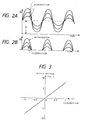
- a waveform of the output voltage V OUT1 is as shown in Fig. 6.
- V A -Rf•Vp• ⁇ •(C2 - C1)
- the movable electrode 4 when no acceleration acts on the acceleration sensing element 1, the movable electrode 4 is set at the mid position between the fixed electrodes 2 and 3. At this position, the capacitance values of the variable capacitors C1 and the C2 are equal to each other.
- the amplitude V A of the output voltage V OUT1 is zero as seen from the equation (1).
- the operational amplifier A1 of the capacitance-difference detector circuit 10 produces voltage of zero as a capacitance-difference detect signal.
- the capacitance values of the variable capacitors C1 and C2 vary, so that the amplitude V A takes a value dependent on the capacitance-difference between the variable capacitors C1 and C2.
- the output voltage V OUT1 of the capacitance-difference detector circuit 10 also vary dependent on the capacitance-difference between the variable capacitors C1 and C2.
- the output voltage V OUT1 varies along a waveform as indicated by a solid line in Fig. 6.
- C1 ⁇ C2 viz., an acceleration acts on the acceleration sensing element 1 in the direction that is opposite to that of the electrostatic power in the previous case
- the capacitance-difference detect voltage V OUT1 varies along a waveform as indicated by a dotted line. In this case, it is phased shifted 180° from the output voltage in the previous case.
- the direction of the acceleration can be judged by synchronizing the sinusoidal wave signal from the oscillator 6 with the capacitance-difference detect voltage V OUT1 of the capacitance-difference detector circuit 10 by the synchronous detector circuit 12.
- the electrostatic power generation/feedback means 15 produces the servo feedback voltage that depends on the output voltage of the capacitance-difference detector circuit 10. This servo feedback voltage is outputted as the output voltage of the acceleration sensor.
- an electrostatic power to reduce the capacitance of the variable capacitor C1 is applied to the fixed- and movable-electrode pairs 2 and 4, and 3 and 4, when C1 > C2.
- the phase of the capacitance-difference detect signal is inverted depending on the direction of the acceleration. Because of this, a small capacitance detecting region is within the phase inverted region. As a result, the linearity of the capacitance-difference detect signal is poor in the vicinity of the 0 point, and the resolution of the capacitor type acceleration sensor is low.
- the capacitance-difference detect voltage whose phase is inverted depending on the direction of the acceleration, varies with time.
- the variation of this voltage takes a sinusoidal waveform varying with respect to the zero voltage, irrespective of the direction of the acceleration.
- the capacitance-difference detect voltage is an AC voltage of a sinusoidal waveform.
- the present invention has an object to provide a capacitor type acceleration sensor which is simple in circuit construction and high in resolution, not using the synchronous detector circuit.
- a capacitor type acceleration sensor based on the electrostatic servo system having an acceleration sensing element having two variable capacitors that are constructed with a couple of fixed electrodes and a movable electrode that is located between the fixed electrodes and movable in response to an acceleration, capacitance-difference detector means for detecting a capacitance difference between the two variable capacitors and for producing the detected capacitance difference in the form of a voltage, and electrostatic power generation/feedback means for applying an electrostatic power to the fixed- and movable-electrode pairs in order to set the movable electrode at a preset reference position in accordance with the output signal of capacitance-difference detector means, the capacitor type acceleration sensor being characterized in that another fixed capacitor of which the capacitance value is larger than the maximum capacitance-difference between the variable capacitors of which the capacitance values vary in accordance with an acceleration, is connected across either of the variable capacitors.
- the electrostatic power generation/feedback means includes a comparator for comparing the integrated value of the output voltage of the capacitance-difference detector means with the reference voltage, and further reference voltage adjusting means for adjusting the reference voltage to be equal to the integrated value of the voltage that is produced from the capacitance-difference detector means when an acceleration is zero.
- the additional fixed capacitor of which the capacitance value is larger than the maximum capacitance-difference between the variable capacitors of which the capacitance values vary in accordance with an acceleration is connected across either of the variable capacitors. Therefore, the capacitance of the variable capacitor coupled with the additional fixed capacitor is larger than that of the variable capacitor not coupled with the additional fixed capacitor, irrespective of the direction of acceleration. Accordingly, the phase of the output voltage of the capacitance-difference detector means is fixed, not inverted. The output signal of the capacitance-difference detector means is monotonously increased or decreased over the entire dynamic range of acceleration. The linearity of the capacitance-difference detect signal is good in the vicinity of a point where the acceleration is zero, and the resolution of the capacitor type acceleration sensor is high.
- Fig. 1 is a circuit diagram showing an embodiment of a capacitor type acceleration sensor according to the present invention.
- the capacitor type acceleration sensor of the present embodiment like the conventional one, includes an acceleration sensing element 1, a capacitance-difference detector circuit 10, and a electrostatic power generation/feedback means 15.
- the capacitor type acceleration sensor of the embodiment is different from the conventional one in that a fixed capacitor Cx and reference voltage adjusting means 18 are additionally provided.
- the fixed capacitor Cx is connected in parallel with the variable capacitor C2 of the acceleration sensing element 1.
- a capacitance value of the fixed capacitor Cx is larger than the maximum capacitance-difference between the variable capacitors C1 and C2 of which the capacitance values vary in accordance with an acceleration.
- the reference voltage adjusting means 18 adjusts the reference voltage, which is to be inputted to the noninverting input terminal of the comparator 13 in the electrostatic power generation/feedback means 15, to be equal to the integrated value of the voltage that is produced from the capacitance-difference detector circuit 10 when an acceleration is zero.
- the capacitance values of the variable capacitors C1 and C2 in the acceleration sensing element 1 are selected as: C1 ⁇ C2.
- the capacitance of the fixed capacitor Cx, which is connected in parallel with the variable capacitor C2, is larger than the maximum capacitance difference between the variable capacitors C1 and C2 over the dynamic range of acceleration.
- the relation (C2 + Cx) > C1 holds. Accordingly, the impedance of (C2 + Cx) is always smaller than that of C1.
- the output terminal of the acceleration sensing element 1 containing the fixed capacitor Cx is connected to the capacitance-difference detector circuit 10.
- the output terminal of the capacitance-difference detector circuit 10 is connected to a pulse-conversion circuit 19 and an analog switch 20.
- An electrostatic power generation/feedback means 15 is connected to the output terminal of the analog switch 20 and the input terminal of the acceleration sensing element 1.
- the electrostatic power generation/feedback means 15 includes an integrator 11, a comparator 13, and a feedback ratio setting circuit (feedback ratio adjustor) 14.
- the integrator 11 includes an operational amplifier A3, a resistor R1, and a capacitor C3.
- the noninverting input terminal of the operational amplifier A3 is earthed.
- the resistor R1 and the capacitor C3, connected in parallel, are inserted between the inverting input terminal and the output terminal of the operational amplifier A3.
- the comparator 13 is connected to the output terminal of the operational amplifier A3.
- the comparator 13 includes an operational amplifier A4, a capacitor C4, a resistor R2, and the reference voltage adjusting means 18.
- the resistor R2 is connected to the inverting input terminal of the operational amplifier A4.
- the capacitor C4 is inserted between the inverting input terminal of the operational amplifier A4 and the output terminal thereof.
- the feedback ratio setting circuit 14 and an integrator/adder 16 are connected to the output terminal of the operational amplifier A4.
- the reference voltage adjusting means 18 is connected to the noninverting input terminal of the operational amplifier A4.
- the reference voltage adjusting means 18 includes an operational amplifier A5, a variable resistor R3 of the slider type, and a couple of power sources 30 and 31.
- the noninverting input terminal of the operational amplifier A5 is connected through the variable resistor R3 to the power sources 30 and 31.
- the output terminal and the inverting input terminal of the operational amplifier A5 are connected to the noninverting input terminal of the operational amplifier A4, through a resistor R5.
- the integrated value Vr of the reference voltage inputted to the operational amplifier A4 is adjusted by slidably operating the variable resistor R3.
- the feedback ratio setting circuit 14 includes an operational amplifier A8, a resistor R8, and a variable resistor R9.
- the inverting input terminal of the operational amplifier A8 is connected to the output terminal of the comparator 13 (more exactly the output terminal of the operational amplifier A4, through the resistor R8, and further to the variable resistor R9.
- the noninverting input terminal and the output terminal of the operational amplifier A8 are interconnected.
- the output terminal of the operational amplifier A8 is connected through the resistor R7 to the inverting input terminal of an operational amplifier A7, and through a resistor R6 to the inverting input terminal of an operational amplifier A6.
- These operational amplifiers A6 and A7 serve as servo adders.
- the output terminal of the operational amplifier A6 is connected to the capacitor C3 (denoted as A in the figure) of the variable capacitor C2 and the fixed capacitor Cx.
- the output terminal of the operational amplifier A7 is connected to the fixed electrode 2 (denoted as B in the figure) of the variable capacitor C1.
- the noninverting input terminals of the operational amplifiers A6 and A7 are both earthed.
- the integrator/adder 16 includes an operational amplifier A10, a parallel circuit of a capacitor C5 and a resistor R10, resistors R11 and R12, and a variable power source 32. As shown, the inverting input terminal of the operational amplifier A10 is connected to the output terminal of the operational amplifier A4, through the resistor R11, and further to the resistor R12 and the variable power source 32. The noninverting input terminal of the operational amplifier A10 is earthed. The parallel circuit of the capacitor C5 and the resistor R10 is inserted between the inverting input terminal and the output terminal of the operational amplifier A10.
- the phase invertor 9 includes an operational amplifier A9.
- the noninverting input terminal of the operational amplifier A9 is earthed.
- the inverting input terminal of the operational amplifier A9 is connected through a resistor R13 to an oscillator 6.
- a resistor R14 is inserted between the output terminal and the inverting input terminal of the operational amplifier A9.
- the output terminal of the operational amplifier A9 is connected-through a resistor R16 to the inverting input terminal of the operational amplifier A7.
- the oscillator 6 is connected to the inverting input terminal of the operational amplifier A6, through a resistor R15.
- a sinusoidal wave signal of an amplitude Vp and at an angular frequency ⁇ , generated by an oscillator 6, is applied to the variable capacitor C2 of the acceleration sensing element 1, through the operational amplifier A6.
- the sinusoidal wave signal, generated by the oscillator 6, is phase shifted 180° by the phase invertor 9, and applied to the variable capacitor C1.
- the amplitude and the angular frequency of the sinusoidal wave signal inverted and applied to the variable capacitor C1 are also Vp and ⁇ .
- V1 -Rf•Vp• ⁇ •Cx - Rf•Vp• ⁇ •(C2 - C1)
- Rf represents resistance of the feedback resistor Rf of the operational amplifier A1
- ⁇ (angular frequency) 2 ⁇ f.
- the output voltage Va of the capacitance-difference detector circuit 10 has an offset voltage of -Rf•Vp• ⁇ •Cx, and has a linear relationship with the capacitance-difference (C2 - C1) between the variable capacitors C1 and C2.
- the equation (2) can be rearranged into the following equation (3).
- V1 -Rf•Vp• ⁇ •(Cx - (C2 - C1))
- the amplitude V1 of the output voltage Va is proportional to a capacitance-difference (Cx - (C2 - C1)), which is the capacitance difference between the capacitance Cx of the fixed capacitor Cx and the capacitance-difference (C2 - C1) between the variable capacitors C1 and C2.
- the capacitance Cx of the fixed capacitor Cx is selected to be larger than the maximum value of the capacitance-difference (C2 - C1). Accordingly, the capacitance Cx is always larger than the capacitance-difference (C2 - C1). And the capacitance-difference (Cx - (C2 - C1)) is positive irrespective of the direction of acceleration. The phase of it is not inverted when the direction of acceleration is changed.
- the output voltage Va of the capacitance-difference detector circuit 10 is a sinusoidal AC voltage whose phase will not be inverted.
- the output voltage Va as the capacitance-difference detect signal has an offset voltage even when the acceleration is zero, as shown in Fig. 2A.
- Each of these AC voltages outputted from the capacitance-difference detector circuit 10 is half-wave rectified by a pulse-conversion circuit 19 and an analog switch 20, into a voltage signal Vb as shown in Fig. 2B.
- the signal Vb is integrated by the integrator 11 into a DC voltage Vc.
- the DC voltage Vc is applied through the input resistor R2 to the inverting input terminal of the operational amplifier A4.
- the reference voltage Vr is adjusted so as to be equal to the integrated value of the output voltage of the capacitance-difference detector circuit 10 when the acceleration is zero, and is inputted to the noninverting input terminal of the operational amplifier A4, from the reference voltage adjusting means 18.
- the operational amplifier A4 compares the reference voltage Vr with the integrated value of the capacitance-difference detect signal that is detected by the capacitance-difference detector circuit 10.
- a difference between the integrated value of the capacitance-difference detect signal and the integrated value of the offset voltage is outputted as a servo voltage Vs.
- the servo voltage Vs is fed back to the operational amplifiers A6 and A7, and to the fixed electrode 3 and 2 of the capacitors C3 and C2, through the feedback ratio setting circuit (feedback ratio adjustor) 14.
- the servo voltage Vs is also applied to the integrator/adder 16 where noise components of the servo voltage Vs, are removed.
- the noise components are offset voltages of the operational amplifiers A1 to A4, for example.
- the servo voltage Vs after the removal of its noise components, is outputted as an output voltage V OUT .
- the output voltage V OUT linearly varies with respect to the acceleration as shown in Fig. 3.
- the result of measuring an acceleration within ⁇ 1G by using the capacitor type acceleration sensor of the present embodiment is plotted in Fig. 3.
- the phase of the capacitance-difference detect signal outputted from the capacitance-difference detector circuit 10 is fixed, not inverted, irrespective of the direction of the acceleration.
- the capacitance-difference detect signal is monotonously increased or decreased over the entire dynamic range of acceleration.
- the phase of the capacitance-difference detect signal is inverted depending on the direction of the acceleration. Because of this, a small capacitance detecting region is within the phase inverted region. As a result, the linearity of the capacitance-difference detect signal is poor in the vicinity of the 0 point, and the resolution of the capacitor type acceleration sensor is low.
- the present invention successfully solves the problem of the conventional capacitor type acceleration sensor.
- the linearity of the capacitance-difference detect signal is good in the vicinity of the 0 point, and the resolution of the capacitor type acceleration sensor is high.
- the capacitor type acceleration sensor of the present invention there is no need of using the synchronous detector circuit for detecting the direction of the acceleration. In this respect, the capacitor type acceleration sensor is simplified in the circuit construction, and hence the sensor cost is reduced.
- the offset voltage of the capacitance-difference detect signal when the acceleration is zero is not reduced to zero.
- the offset voltage other than zero is present also when the acceleration is zero.
- the integrated value of the offset voltage is adjusted by the reference voltage adjusting means 18, whereby the movable electrode 4 is set at the reference position.
- the present invention eliminates the troublesome work to adjust the variable capacitors C1 and C2 so as to have exactly equal capacitance values, the work being essential to the conventional capacitor type acceleration sensor. Accordingly, the capacitor type acceleration sensor of the present invention is able to exactly sense an acceleration even if it suffers from the product variation.
- the fixed capacitor Cx may be connected in parallel with the variable capacitor C1, while it is connected in parallel with the variable capacitor C2 in the embodiment.
- the integrator/adder 16 for removing the noise components of the operational amplifiers A1 to A4, which is connected to the output of the capacitor type acceleration sensor, may be removed if required.
- the integrated value Vr to be inputted to the operational amplifier A4 of the comparator 13 is adjusted by the reference voltage adjusting means 18 that is connected to the noninverting input terminal of the operational amplifier A4.
- the reference voltage adjusting means 18 may be substituted by a power source which produces a fixed reference voltage.
- the offset voltage signal is contained in the output signal of the comparator 13. However, it can be removed by using a circuit for removing the offset voltage signal at a proper location in the circuit.
- the additional fixed capacitor of which the capacitance value is larger than the maximum capacitance-difference between the variable capacitors of which the capacitance values vary in accordance with an acceleration is connected in parallel with either of the variable capacitors. Accordingly, the phase of the output voltage of the capacitance-difference detector means is not inverted depending on the direction of acceleration.
- the magnitude and the direction of the acceleration can easily be known from the output signal of the capacitance-difference detector means.
- the linearity of the capacitance-difference detect signal is good even in the small acceleration detecting region, and the resolution (detect accuracy and a detect sensitivity) of the capacitor type acceleration sensor is high. There is no need of using the synchronous detector circuit for detecting the direction of the acceleration, so that the capacitor type acceleration sensor is simplified in the circuit construction, and hence the sensor cost is reduced.
- the capacitor type acceleration sensor includes reference voltage adjusting means for adjusting the reference voltage that is to be inputted to the comparator of the electrostatic power generation/feedback means, to be equal to the integrated value of the voltage that is produced from the capacitance-difference detector means when an acceleration is zero.
- the reference voltage is adjusted by the reference voltage adjusting means, so that an electrostatic power for setting the movable electrode at a preset standard position is adjusted.
- the reference voltage to be inputted to the comparator is reduced to zero, and to this end, the capacitance values of the two variable capacitors must be adjusted to exactly be equal to each other.
- the capacitor type acceleration sensor of the present invention is free from such troublesome work.
- the capacitor type acceleration sensor of the invention is able to exactly sense an acceleration even if the capacitance values of the two variable capacitors are deviated from the designed ones. This fact makes it easy to manufacture the acceleration sensing element of the capacitor type acceleration sensor.
Applications Claiming Priority (2)
| Application Number | Priority Date | Filing Date | Title |
|---|---|---|---|
| JP06222592A JP3139305B2 (ja) | 1994-08-24 | 1994-08-24 | 容量型加速度センサ |
| JP222592/94 | 1994-08-24 |
Publications (2)
| Publication Number | Publication Date |
|---|---|
| EP0703459A1 true EP0703459A1 (fr) | 1996-03-27 |
| EP0703459B1 EP0703459B1 (fr) | 1999-06-02 |
Family
ID=16784889
Family Applications (1)
| Application Number | Title | Priority Date | Filing Date |
|---|---|---|---|
| EP95113187A Expired - Lifetime EP0703459B1 (fr) | 1994-08-24 | 1995-08-22 | Capteur d'accélération de type capacitif |
Country Status (4)
| Country | Link |
|---|---|
| US (1) | US5597956A (fr) |
| EP (1) | EP0703459B1 (fr) |
| JP (1) | JP3139305B2 (fr) |
| DE (1) | DE69509992T2 (fr) |
Families Citing this family (73)
| Publication number | Priority date | Publication date | Assignee | Title |
|---|---|---|---|---|
| JP3198922B2 (ja) * | 1996-07-03 | 2001-08-13 | 株式会社村田製作所 | 静電容量型センサの製造方法 |
| US5808198A (en) * | 1997-05-19 | 1998-09-15 | The Charles Stark Draper Laboratory, Inc. | RF balanced capacitive vibration sensor system |
| JPH1114658A (ja) * | 1997-06-25 | 1999-01-22 | Mitsubishi Electric Corp | 静電容量式加速度センサ |
| US6530275B1 (en) | 1999-08-31 | 2003-03-11 | Analog Devices, Inc. | Feedback circuit for micromachined accelerometer |
| US7120495B2 (en) * | 2000-09-18 | 2006-10-10 | Cameron Health, Inc. | Flexible subcutaneous implantable cardioverter-defibrillator |
| US6950705B2 (en) | 2000-09-18 | 2005-09-27 | Cameron Health, Inc. | Canister designs for implantable cardioverter-defibrillators |
| US20020035377A1 (en) * | 2000-09-18 | 2002-03-21 | Cameron Health, Inc. | Subcutaneous electrode for transthoracic conduction with insertion tool |
| US6754528B2 (en) | 2001-11-21 | 2004-06-22 | Cameraon Health, Inc. | Apparatus and method of arrhythmia detection in a subcutaneous implantable cardioverter/defibrillator |
| US20020035378A1 (en) * | 2000-09-18 | 2002-03-21 | Cameron Health, Inc. | Subcutaneous electrode for transthoracic conduction with highly maneuverable insertion tool |
| US6927721B2 (en) * | 2001-11-05 | 2005-08-09 | Cameron Health, Inc. | Low power A/D converter |
| US6778860B2 (en) | 2001-11-05 | 2004-08-17 | Cameron Health, Inc. | Switched capacitor defibrillation circuit |
| US7043299B2 (en) | 2000-09-18 | 2006-05-09 | Cameron Health, Inc. | Subcutaneous implantable cardioverter-defibrillator employing a telescoping lead |
| US7065407B2 (en) | 2000-09-18 | 2006-06-20 | Cameron Health, Inc. | Duckbill-shaped implantable cardioverter-defibrillator canister and method of use |
| US20020095184A1 (en) * | 2000-09-18 | 2002-07-18 | Bardy Gust H. | Monophasic waveform for anti-tachycardia pacing for a subcutaneous implantable cardioverter-defibrillator |
| US6721597B1 (en) * | 2000-09-18 | 2004-04-13 | Cameron Health, Inc. | Subcutaneous only implantable cardioverter defibrillator and optional pacer |
| US7069080B2 (en) | 2000-09-18 | 2006-06-27 | Cameron Health, Inc. | Active housing and subcutaneous electrode cardioversion/defibrillating system |
| US7194309B2 (en) * | 2000-09-18 | 2007-03-20 | Cameron Health, Inc. | Packaging technology for non-transvenous cardioverter/defibrillator devices |
| US7090682B2 (en) | 2000-09-18 | 2006-08-15 | Cameron Health, Inc. | Method and apparatus for extraction of a subcutaneous electrode |
| US6866044B2 (en) | 2000-09-18 | 2005-03-15 | Cameron Health, Inc. | Method of insertion and implantation of implantable cardioverter-defibrillator canisters |
| US6788974B2 (en) * | 2000-09-18 | 2004-09-07 | Cameron Health, Inc. | Radian curve shaped implantable cardioverter-defibrillator canister |
| US20020107544A1 (en) * | 2000-09-18 | 2002-08-08 | Cameron Health, Inc. | Current waveform for anti-bradycardia pacing for a subcutaneous implantable cardioverter-defibrillator |
| US6988003B2 (en) * | 2000-09-18 | 2006-01-17 | Cameron Health, Inc. | Implantable cardioverter-defibrillator having two spaced apart shocking electrodes on housing |
| US7039465B2 (en) | 2000-09-18 | 2006-05-02 | Cameron Health, Inc. | Ceramics and/or other material insulated shell for active and non-active S-ICD can |
| US6937907B2 (en) * | 2000-09-18 | 2005-08-30 | Cameron Health, Inc. | Subcutaneous electrode for transthoracic conduction with low-profile installation appendage and method of doing same |
| US20020035379A1 (en) | 2000-09-18 | 2002-03-21 | Bardy Gust H. | Subcutaneous electrode for transthoracic conduction with improved installation characteristics |
| US7146212B2 (en) * | 2000-09-18 | 2006-12-05 | Cameron Health, Inc. | Anti-bradycardia pacing for a subcutaneous implantable cardioverter-defibrillator |
| US20020035381A1 (en) * | 2000-09-18 | 2002-03-21 | Cameron Health, Inc. | Subcutaneous electrode with improved contact shape for transthoracic conduction |
| US7076296B2 (en) * | 2000-09-18 | 2006-07-11 | Cameron Health, Inc. | Method of supplying energy to subcutaneous cardioverter-defibrillator and pacer |
| US6952610B2 (en) * | 2000-09-18 | 2005-10-04 | Cameron Health, Inc. | Current waveforms for anti-tachycardia pacing for a subcutaneous implantable cardioverter- defibrillator |
| US7194302B2 (en) * | 2000-09-18 | 2007-03-20 | Cameron Health, Inc. | Subcutaneous cardiac stimulator with small contact surface electrodes |
| US7248921B2 (en) * | 2003-06-02 | 2007-07-24 | Cameron Health, Inc. | Method and devices for performing cardiac waveform appraisal |
| US7392085B2 (en) * | 2001-11-21 | 2008-06-24 | Cameron Health, Inc. | Multiple electrode vectors for implantable cardiac treatment devices |
| US7330757B2 (en) * | 2001-11-21 | 2008-02-12 | Cameron Health, Inc. | Method for discriminating between ventricular and supraventricular arrhythmias |
| US20040199082A1 (en) * | 2003-04-03 | 2004-10-07 | Ostroff Alan H. | Selctable notch filter circuits |
| US6901801B2 (en) * | 2003-07-28 | 2005-06-07 | The Boeing Company | Capacitance acceleration derivative detector |
| US7124634B2 (en) * | 2003-07-29 | 2006-10-24 | The Boeing Company | Single plate capacitive acceleration derivative detector |
| KR100601953B1 (ko) * | 2004-05-03 | 2006-07-14 | 삼성전자주식회사 | 메모리 소자의 캐패시터 및 그 제조 방법 |
| US7310577B2 (en) * | 2004-09-29 | 2007-12-18 | The Boeing Company | Integrated capacitive bridge and integrated flexure functions inertial measurement unit |
| US20060089681A1 (en) * | 2004-10-21 | 2006-04-27 | Cameron Health, Inc. | Implantable medical device |
| US7360425B2 (en) * | 2004-11-22 | 2008-04-22 | The Boeing Company | Compensated composite structure |
| US7228739B2 (en) | 2004-11-23 | 2007-06-12 | The Boeing Company | Precision flexure plate |
| US7477935B2 (en) * | 2004-11-29 | 2009-01-13 | Cameron Health, Inc. | Method and apparatus for beat alignment and comparison |
| US7376458B2 (en) * | 2004-11-29 | 2008-05-20 | Cameron Health, Inc. | Method for defining signal templates in implantable cardiac devices |
| US7655014B2 (en) * | 2004-12-06 | 2010-02-02 | Cameron Health, Inc. | Apparatus and method for subcutaneous electrode insertion |
| US7331229B2 (en) * | 2004-12-09 | 2008-02-19 | The Boeing Company | Magnetic null accelerometer |
| US7137208B2 (en) * | 2004-12-14 | 2006-11-21 | The Boeing Company | Leveling device |
| JP2006184124A (ja) * | 2004-12-27 | 2006-07-13 | Fab Solution Kk | 電流測定装置及び電流測定方法 |
| US8229563B2 (en) * | 2005-01-25 | 2012-07-24 | Cameron Health, Inc. | Devices for adapting charge initiation for an implantable cardioverter-defibrillator |
| US8160697B2 (en) | 2005-01-25 | 2012-04-17 | Cameron Health, Inc. | Method for adapting charge initiation for an implantable cardioverter-defibrillator |
| US7296470B2 (en) * | 2005-04-14 | 2007-11-20 | The Boeing Company | Extended accuracy flexured plate dual capacitance accelerometer |
| US7555338B2 (en) * | 2005-04-26 | 2009-06-30 | Cameron Health, Inc. | Methods and implantable devices for inducing fibrillation by alternating constant current |
| US8116867B2 (en) * | 2005-08-04 | 2012-02-14 | Cameron Health, Inc. | Methods and devices for tachyarrhythmia sensing and high-pass filter bypass |
| US7368923B2 (en) * | 2005-12-22 | 2008-05-06 | Honeywell International Inc. | Time interval trimmed differential capacitance sensor |
| US20070276452A1 (en) * | 2006-05-26 | 2007-11-29 | Cameron Health, Inc. | Implantable medical device systems having initialization functions and methods of operation |
| US8200341B2 (en) | 2007-02-07 | 2012-06-12 | Cameron Health, Inc. | Sensing vector selection in a cardiac stimulus device with postural assessment |
| US8788023B2 (en) | 2006-05-26 | 2014-07-22 | Cameron Health, Inc. | Systems and methods for sensing vector selection in an implantable medical device |
| US7623909B2 (en) | 2006-05-26 | 2009-11-24 | Cameron Health, Inc. | Implantable medical devices and programmers adapted for sensing vector selection |
| US7783340B2 (en) | 2007-01-16 | 2010-08-24 | Cameron Health, Inc. | Systems and methods for sensing vector selection in an implantable medical device using a polynomial approach |
| US20080015644A1 (en) * | 2006-07-14 | 2008-01-17 | Cameron Health, Inc. | End of life battery testing in an implantable medical device |
| US7623913B2 (en) | 2006-08-01 | 2009-11-24 | Cameron Health, Inc. | Implantable medical devices using heuristic filtering in cardiac event detection |
| US8718793B2 (en) | 2006-08-01 | 2014-05-06 | Cameron Health, Inc. | Electrode insertion tools, lead assemblies, kits and methods for placement of cardiac device electrodes |
| US7877139B2 (en) | 2006-09-22 | 2011-01-25 | Cameron Health, Inc. | Method and device for implantable cardiac stimulus device lead impedance measurement |
| US8014851B2 (en) * | 2006-09-26 | 2011-09-06 | Cameron Health, Inc. | Signal analysis in implantable cardiac treatment devices |
| US7623916B2 (en) | 2006-12-20 | 2009-11-24 | Cameron Health, Inc. | Implantable cardiac stimulus devices and methods with input recharge circuitry |
| DE102007027652B4 (de) * | 2007-06-15 | 2013-06-20 | Litef Gmbh | Betriebsverfahren und Schaltungsanordnung für einen kapazitiven mikromechanischen Sensor mit analoger Rückstellung |
| JP2009098007A (ja) * | 2007-10-17 | 2009-05-07 | Denso Corp | 物理量センサ |
| DE102008023535B4 (de) * | 2008-05-14 | 2011-05-12 | Texas Instruments Deutschland Gmbh | Elektronische Vorrichtung und Verfahren zur Auswertung einer variablen Kapazität |
| US8171793B2 (en) * | 2008-07-31 | 2012-05-08 | Honeywell International Inc. | Systems and methods for detecting out-of-plane linear acceleration with a closed loop linear drive accelerometer |
| JP2011169630A (ja) * | 2010-02-16 | 2011-09-01 | Asahi Kasei Electronics Co Ltd | 静電容量型加速度センサ及び静電容量型加速度検出装置 |
| US20120090393A1 (en) * | 2010-06-18 | 2012-04-19 | Baolab Microsystems Sl | Unstable electrostatic spring accelerometer |
| JP6140919B2 (ja) * | 2011-09-30 | 2017-06-07 | 曙ブレーキ工業株式会社 | 加速度センサ回路 |
| EP2967404B1 (fr) | 2013-03-11 | 2019-05-22 | Cameron Health, Inc. | Dispositif d'implémentation de critères doubles pour la détection des arythmies |
| US9579065B2 (en) | 2013-03-12 | 2017-02-28 | Cameron Health Inc. | Cardiac signal vector selection with monophasic and biphasic shape consideration |
Citations (3)
| Publication number | Priority date | Publication date | Assignee | Title |
|---|---|---|---|---|
| DE3831593A1 (de) * | 1988-09-15 | 1990-03-22 | Siemens Ag | Schaltungsanordnung mit einer einer mechanischen verstimmung ausgesetzten differentialkondensator-anordnung |
| EP0459723A2 (fr) * | 1990-05-30 | 1991-12-04 | Hitachi, Ltd. | Capteur d'accélération à semi-conducteur et système de commande de véhicule utilisant celui-ci |
| US5325065A (en) * | 1992-05-18 | 1994-06-28 | Motorola, Inc. | Detection circuit with dummy integrator to compensate for switch charge insection and amplifier offset voltage |
Family Cites Families (3)
| Publication number | Priority date | Publication date | Assignee | Title |
|---|---|---|---|---|
| US3662595A (en) * | 1970-03-19 | 1972-05-16 | Bendix Corp | Oscillator type force measuring system insensitive to input voltage variations |
| FR2656698B1 (fr) * | 1989-12-29 | 1992-05-07 | Vectavib | Dispositif de mesure des variations de la capacite d'un condensateur formant, notamment, un capteur. |
| EP0543901B1 (fr) * | 1990-08-17 | 1995-10-04 | Analog Devices, Inc. | Accelerometre monolithique |
-
1994
- 1994-08-24 JP JP06222592A patent/JP3139305B2/ja not_active Expired - Fee Related
-
1995
- 1995-08-18 US US08/516,933 patent/US5597956A/en not_active Expired - Lifetime
- 1995-08-22 DE DE69509992T patent/DE69509992T2/de not_active Expired - Lifetime
- 1995-08-22 EP EP95113187A patent/EP0703459B1/fr not_active Expired - Lifetime
Patent Citations (3)
| Publication number | Priority date | Publication date | Assignee | Title |
|---|---|---|---|---|
| DE3831593A1 (de) * | 1988-09-15 | 1990-03-22 | Siemens Ag | Schaltungsanordnung mit einer einer mechanischen verstimmung ausgesetzten differentialkondensator-anordnung |
| EP0459723A2 (fr) * | 1990-05-30 | 1991-12-04 | Hitachi, Ltd. | Capteur d'accélération à semi-conducteur et système de commande de véhicule utilisant celui-ci |
| US5325065A (en) * | 1992-05-18 | 1994-06-28 | Motorola, Inc. | Detection circuit with dummy integrator to compensate for switch charge insection and amplifier offset voltage |
Also Published As
| Publication number | Publication date |
|---|---|
| DE69509992T2 (de) | 2000-01-20 |
| EP0703459B1 (fr) | 1999-06-02 |
| US5597956A (en) | 1997-01-28 |
| JPH0862248A (ja) | 1996-03-08 |
| DE69509992D1 (de) | 1999-07-08 |
| JP3139305B2 (ja) | 2001-02-26 |
Similar Documents
| Publication | Publication Date | Title |
|---|---|---|
| EP0703459B1 (fr) | Capteur d'accélération de type capacitif | |
| JP3216455B2 (ja) | 容量型静電サーボ加速度センサ | |
| US4584885A (en) | Capacitive detector for transducers | |
| US5440939A (en) | Servo-controlled pendular micro-sensor | |
| US5977803A (en) | Capacitance type sensor interface circuit | |
| US5641911A (en) | Method and apparatus for feedback-control of an asymmetric differential pressure transducer | |
| EP0196735A2 (fr) | Détecteur capacitif différentiel | |
| US5283528A (en) | Circuit arrangement for measuring the ratio of the capacitance values of two capacitors | |
| US6630834B2 (en) | Apparatus and method for measuring change in capacitance | |
| US20040196617A1 (en) | Capacitance-sensing vibratory gyro and method for detecting change in capacitance | |
| EP0742445A2 (fr) | Procédé et dispositif de mesure du changement de capacités de condensateurs doubles | |
| CN111693784A (zh) | 一种微弱电容变化测量电路 | |
| US5210501A (en) | Apparatus for processing sensor signals having switch-capacitor structures | |
| JP2865752B2 (ja) | 交流信号発生装置 | |
| JP2520137B2 (ja) | 位置検出装置 | |
| JPH07260510A (ja) | 容量型センサ | |
| JP2000221054A (ja) | 容量式物理量検出装置 | |
| JP3322726B2 (ja) | 静電容量検出回路 | |
| US6215319B1 (en) | High accuracy measuring system | |
| CN212646814U (zh) | 一种微弱电容变化测量电路 | |
| JP3265807B2 (ja) | 容量型センサ | |
| SU1525619A1 (ru) | Преобразователь параметров емкостных датчиков во временной интервал и напр жение | |
| JPH0425771A (ja) | 容量検出回路 | |
| JP3356888B2 (ja) | 静電容量式センサの信号処理回路 | |
| RU2103676C1 (ru) | Способ компенсации последовательного активного сопротивления электрохимической ячейки в вольтамперометрии |
Legal Events
| Date | Code | Title | Description |
|---|---|---|---|
| PUAI | Public reference made under article 153(3) epc to a published international application that has entered the european phase |
Free format text: ORIGINAL CODE: 0009012 |
|
| AK | Designated contracting states |
Kind code of ref document: A1 Designated state(s): DE FR |
|
| 17P | Request for examination filed |
Effective date: 19960620 |
|
| GRAG | Despatch of communication of intention to grant |
Free format text: ORIGINAL CODE: EPIDOS AGRA |
|
| 17Q | First examination report despatched |
Effective date: 19980831 |
|
| GRAG | Despatch of communication of intention to grant |
Free format text: ORIGINAL CODE: EPIDOS AGRA |
|
| GRAH | Despatch of communication of intention to grant a patent |
Free format text: ORIGINAL CODE: EPIDOS IGRA |
|
| GRAH | Despatch of communication of intention to grant a patent |
Free format text: ORIGINAL CODE: EPIDOS IGRA |
|
| GRAA | (expected) grant |
Free format text: ORIGINAL CODE: 0009210 |
|
| AK | Designated contracting states |
Kind code of ref document: B1 Designated state(s): DE FR |
|
| REF | Corresponds to: |
Ref document number: 69509992 Country of ref document: DE Date of ref document: 19990708 |
|
| ET | Fr: translation filed | ||
| PLBE | No opposition filed within time limit |
Free format text: ORIGINAL CODE: 0009261 |
|
| STAA | Information on the status of an ep patent application or granted ep patent |
Free format text: STATUS: NO OPPOSITION FILED WITHIN TIME LIMIT |
|
| 26N | No opposition filed | ||
| PGFP | Annual fee paid to national office [announced via postgrant information from national office to epo] |
Ref country code: FR Payment date: 20110818 Year of fee payment: 17 Ref country code: DE Payment date: 20110817 Year of fee payment: 17 |
|
| REG | Reference to a national code |
Ref country code: FR Ref legal event code: ST Effective date: 20130430 |
|
| PG25 | Lapsed in a contracting state [announced via postgrant information from national office to epo] |
Ref country code: DE Free format text: LAPSE BECAUSE OF NON-PAYMENT OF DUE FEES Effective date: 20130301 |
|
| PG25 | Lapsed in a contracting state [announced via postgrant information from national office to epo] |
Ref country code: FR Free format text: LAPSE BECAUSE OF NON-PAYMENT OF DUE FEES Effective date: 20120831 |
|
| REG | Reference to a national code |
Ref country code: DE Ref legal event code: R119 Ref document number: 69509992 Country of ref document: DE Effective date: 20130301 |