EP0703107A2 - Fahrzeugtür - Google Patents
Fahrzeugtür Download PDFInfo
- Publication number
- EP0703107A2 EP0703107A2 EP95110462A EP95110462A EP0703107A2 EP 0703107 A2 EP0703107 A2 EP 0703107A2 EP 95110462 A EP95110462 A EP 95110462A EP 95110462 A EP95110462 A EP 95110462A EP 0703107 A2 EP0703107 A2 EP 0703107A2
- Authority
- EP
- European Patent Office
- Prior art keywords
- glass pane
- guide
- pane
- guide rails
- door
- Prior art date
- Legal status (The legal status is an assumption and is not a legal conclusion. Google has not performed a legal analysis and makes no representation as to the accuracy of the status listed.)
- Withdrawn
Links
Images


Classifications
-
- E—FIXED CONSTRUCTIONS
- E05—LOCKS; KEYS; WINDOW OR DOOR FITTINGS; SAFES
- E05F—DEVICES FOR MOVING WINGS INTO OPEN OR CLOSED POSITION; CHECKS FOR WINGS; WING FITTINGS NOT OTHERWISE PROVIDED FOR, CONCERNED WITH THE FUNCTIONING OF THE WING
- E05F11/00—Man-operated mechanisms for operating wings, including those which also operate the fastening
- E05F11/38—Man-operated mechanisms for operating wings, including those which also operate the fastening for sliding windows, e.g. vehicle windows, to be opened or closed by vertical movement
- E05F11/48—Man-operated mechanisms for operating wings, including those which also operate the fastening for sliding windows, e.g. vehicle windows, to be opened or closed by vertical movement operated by cords or chains or other flexible elongated pulling elements, e.g. tapes
- E05F11/481—Man-operated mechanisms for operating wings, including those which also operate the fastening for sliding windows, e.g. vehicle windows, to be opened or closed by vertical movement operated by cords or chains or other flexible elongated pulling elements, e.g. tapes for vehicle windows
- E05F11/483—Man-operated mechanisms for operating wings, including those which also operate the fastening for sliding windows, e.g. vehicle windows, to be opened or closed by vertical movement operated by cords or chains or other flexible elongated pulling elements, e.g. tapes for vehicle windows by cables
- E05F11/488—Man-operated mechanisms for operating wings, including those which also operate the fastening for sliding windows, e.g. vehicle windows, to be opened or closed by vertical movement operated by cords or chains or other flexible elongated pulling elements, e.g. tapes for vehicle windows by cables with two cable connections to the window glass
-
- B—PERFORMING OPERATIONS; TRANSPORTING
- B60—VEHICLES IN GENERAL
- B60J—WINDOWS, WINDSCREENS, NON-FIXED ROOFS, DOORS, OR SIMILAR DEVICES FOR VEHICLES; REMOVABLE EXTERNAL PROTECTIVE COVERINGS SPECIALLY ADAPTED FOR VEHICLES
- B60J5/00—Doors
- B60J5/04—Doors arranged at the vehicle sides
- B60J5/0412—Lower door structure
- B60J5/0416—Assembly panels to be installed in doors as a module with components, e.g. lock or window lifter, attached thereto
-
- E—FIXED CONSTRUCTIONS
- E05—LOCKS; KEYS; WINDOW OR DOOR FITTINGS; SAFES
- E05Y—INDEXING SCHEME ASSOCIATED WITH SUBCLASSES E05D AND E05F, RELATING TO CONSTRUCTION ELEMENTS, ELECTRIC CONTROL, POWER SUPPLY, POWER SIGNAL OR TRANSMISSION, USER INTERFACES, MOUNTING OR COUPLING, DETAILS, ACCESSORIES, AUXILIARY OPERATIONS NOT OTHERWISE PROVIDED FOR, APPLICATION THEREOF
- E05Y2600/00—Mounting or coupling arrangements for elements provided for in this subclass
- E05Y2600/50—Mounting methods; Positioning
- E05Y2600/56—Positioning, e.g. re-positioning, or pre-mounting
-
- E—FIXED CONSTRUCTIONS
- E05—LOCKS; KEYS; WINDOW OR DOOR FITTINGS; SAFES
- E05Y—INDEXING SCHEME ASSOCIATED WITH SUBCLASSES E05D AND E05F, RELATING TO CONSTRUCTION ELEMENTS, ELECTRIC CONTROL, POWER SUPPLY, POWER SIGNAL OR TRANSMISSION, USER INTERFACES, MOUNTING OR COUPLING, DETAILS, ACCESSORIES, AUXILIARY OPERATIONS NOT OTHERWISE PROVIDED FOR, APPLICATION THEREOF
- E05Y2800/00—Details, accessories and auxiliary operations not otherwise provided for
- E05Y2800/74—Specific positions
- E05Y2800/742—Specific positions abnormal
-
- E—FIXED CONSTRUCTIONS
- E05—LOCKS; KEYS; WINDOW OR DOOR FITTINGS; SAFES
- E05Y—INDEXING SCHEME ASSOCIATED WITH SUBCLASSES E05D AND E05F, RELATING TO CONSTRUCTION ELEMENTS, ELECTRIC CONTROL, POWER SUPPLY, POWER SIGNAL OR TRANSMISSION, USER INTERFACES, MOUNTING OR COUPLING, DETAILS, ACCESSORIES, AUXILIARY OPERATIONS NOT OTHERWISE PROVIDED FOR, APPLICATION THEREOF
- E05Y2900/00—Application of doors, windows, wings or fittings thereof
- E05Y2900/50—Application of doors, windows, wings or fittings thereof for vehicles
- E05Y2900/53—Type of wing
- E05Y2900/55—Windows
Definitions
- the present invention relates to a vehicle door with an outer door panel, an inner door panel and, if necessary, an intermediate support panel, a glass pane which can be opened and closed by means of a window lifter, and which is fastened in guide rails fastened between the outer and inner door panels by means of one or more at the lower edge of the Glass pane fixed bolt is guided, wherein the door inner panel has a mounting cutout for the glass pane, and wherein a door window shaft is provided below the glass pane field.
- the height to the width of the glass pane is in a narrow ratio. The result of this is that as the width of the glass pane increases, the height also increases accordingly, but the width of the glass pane is always greater than the height.
- the glass pane is installed using a mounting cutout that is recessed from the inner door panel. The height of the cut-out is at least as large as the largest height of the glass pane. To mount the glass pane in the mounting cutout, it is tilted and moved so that it fits into the cutout can be introduced. At the lower edge of the pane, a lifting rail is fixed on the side facing away from the inner door panel.
- the window lifter is arranged as a construction or assembly unit on a carrier plate which can be fastened to the inner door panel so that it is located together with the glass pane in the interior of the door lying between the inner and outer door panels.
- at least two bolts are attached to the lower edge of the glass pane, which protrude from the glass pane and are guided in the upright guide rails.
- the disadvantage of this construction is that, in the worst case, only the length of the guide rail reduced by the shaft height is available for guiding the glass pane, since the height of the glass pane must be such that in the upper closed position the lower edge area is still in the assembly cutout of the Door inner plate is in the upper area of the guide rails. It follows it turns out that the height of the glass pane must be significantly greater than the height of the glass pane field. On the other hand, the height of the glass pane must not be greater than the clear height of the mounting cutout, otherwise the mounting cutout would have to be enlarged. This would be very disadvantageous because the window sizes and height ratios of the vehicle doors are in very limited proportions. With increasing size of the mounting cut-out, the stability of the vehicle doors is inevitably reduced.
- the invention is therefore based on the object of designing a vehicle door of the type described in more detail above while observing predetermined dimensions so that the mounting cutout is as small as possible and the height of the guide rails can be used almost completely to guide the pane.
- a linear guide extending in the longitudinal direction of the guide rails for the glass pane and / or for the guide rails, the length of the linear guide being considerably less than the lengths of the guide rails, so that the glass pane is opposite the carrier plate by a lower mounting position in the direction of the glass pane in a lower operating position is displaceable, the displacement path corresponds to the length of the linear guide.
- the pane height can be significantly lower than in the previously known designs, since in the upper closed position of the glass pane, its lower edge region is significantly higher. This is made possible by moving the glass pane with respect to the driver parts from the lower assembly position to the raised, lower operating position. This shift takes place immediately after inserting the glass pane and the window lifter mounted on the carrier plate into the mounting cutout. In this position, the bolts are in the lower end areas of the linear guide. To guide the upper edge of the glass pane within the door window shaft, the glass pane is pushed upwards into the intermediate position as before. This is made possible by the linear guide. When the glass pane is moved into the upper closed position, the associated driver part is then taken along by the bolts.
- the glass pane is inserted through the mounting cutout into the door interior by the glass pane is first pushed with a broad side, if necessary, by tilting and laterally moving it under a side edge of the mounting cutout and is brought into the basic position within the mounting cutout by an opposite transverse movement. Due to the lower pane height, a large saving in material is achieved, which significantly reduces costs. In addition, the height and possibly also the width of the mounting cutout can be reduced, so that the stability of the vehicle door becomes considerably greater.
- a driver part provided with an elongated hole extending in the direction of displacement of the glass pane is slidably guided in each guide rail, and that the bolt engages in the elongated hole of the driver part in such a way that the glass pane is opposite the driver part is displaceable, the bolt being in contact with the lower end of the elongated hole in a lower mounting position of the glass pane and with the upper end of the elongated hole in the closed position of the glass pane.
- This design is particularly simple in terms of construction, since the additional additional effort relates to the two Driver parts limited.
- the driver parts do not move. However, if the glass pane is moved upwards into a closed position, the driver parts are taken along. They act in the same way as an extension of the guide rails, whereby the reduced height of the glass pane is achieved.
- two elongated holes are provided in the region of the guide rails for forming the linear guide, and that two holders guided in the elongated holes are fastened to the guide rails, so that the guide rails with the glass pane can be displaced relative to the carrier plate , wherein in a lower mounting position of the glass pane, the holders rest on the lower end of the elongated holes and in the closed position of the glass pane on the upper ends of the elongated holes. Due to the possible displacement of the guide rails, an extension is also achieved here, which leads to a reduction in the height of the glass pane.
- the height of the elongated hole essentially corresponds to the distance between the upper edge of the mounting cutout and the lower edge of the glass pane field.
- the upper edge of the glass pane is guided within the door window shaft when the glass pane is transferred from the installation insertion position to the intermediate position.
- a structurally simple solution for the full utilization of the height of each guide rail using the driver parts is advantageously achieved in that each driver part has at least one guide pin or guide projection which engages in the associated guide rail, the guide pin being arranged in the lower region of the driver part.
- the bolt engaging in the elongated hole is offset in the upper position from the guide pin or guide shoulder.
- the upper end faces of the guide rails and the upper end faces of the driver parts are also offset in height, the upper end faces of the driver parts being in any case higher than the end faces of the guide rails.
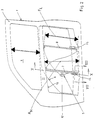
- the vehicle door 1 shown in the figures consists essentially of an outer door panel 2, an inner door panel 3 spaced apart therefrom, a carrier panel 4 on which a window regulator 5 is fixed as a structural unit, a glass pane 6 and two Guide rails 7, 8 for the glass pane 6.
- the guide rails 7, 8 are essentially parallel and at a distance from one another.
- the vehicle door 1 is provided with a glass pane field 9, which is covered by the glass pane 6 in the upper operating position.
- the vehicle door 1 is equipped with a mounting cutout 10.
- the door window shaft reinforcement 11 is located between the glass pane field 9 and the mounting cutout 10.
- the width of the glass pane 6 is a little smaller than the inside width of the mounting cutout 10.
- the width of the glass pane 6 can also be a little be greater than the clear width of the mounting cutout 10.
- the height of the disc is also always slightly smaller than the height of the mounting cutout. It is clear from the figures that the width of the glass pane 6 and thus also the width of the mounting cutout 10 is substantially larger than the height of the glass sheet or the mounting cutout.
- the window lifter 5 is not shown in detail. Only the drive is identified by reference number 12. The window lifter 5 is attached as a prefabricated unit to a carrier plate 4, which is not shown is attached to the inner door panel 3. In the lower region of the glass pane 6, guide bolts 13 are fastened in the correct position relative to the guide rails 7, 8. According to the exemplary embodiment according to FIGS.
- each driver profile piece 14 or 15 is equipped with an elongated hole 16 extending in the longitudinal direction, in which the associated guide pin engages.
- the guide bolts protrude from the side of the glass pane facing the inner door panel (3). At the free end, they are provided with a collar, so that a guide through the slot 16 is given.
- each driver part 14, 15 is equipped with a guide projection 17 which engages in the associated guide rail 7 or 8 in a manner that is not explained in more detail.
- FIG. 3 shows that the lower edge of the glass pane 6 is above and at a distance from the upper end edges of the guide rails 7, 8 in the closed position. It follows from this that the height of the glass pane 6 and thus also the material costs can be significantly reduced.
- the carrier plate 4 fixed to the inner door panel 3 is provided with an opening which is covered by a closure cap 18.
- the driver profile pieces 14, 15 are designed, which enable a relative movement in the assembly position between the glass pane 6 and the driver profile pieces 14, 15. It is also essential that the full height of the fixed guide rails 7, 8 can be used.
- the guide rails 7, 8 can be fastened to the door inner panel 3 in a manner not shown via struts or similar components.
- FIGS. 10-13 A further exemplary embodiment of a vehicle door according to the invention is shown in FIGS. 10-13.
- the same components are identified by the same reference numerals.
- two holders 19, 20 are attached to the two guide rails 7, 8 in the upper and lower regions. This arrangement is shown in FIGS. 12, 12A, 13.
- the holders 19, 20 are trapezoidal.
- the leg parallel to the guide rails 7 and 8 adjoins the carrier plate 4.
- a guide pin 21 in the form of a screw is assigned to each holder 19, 20 of the two guide rails 7, 8.
- Each guide pin 21 is guided in an elongated hole 22.
- the slots 22 form a linear guide in their entirety.
- the guide bolts 13 attached to the glass pane 6 engage in guide pieces 23, but cannot be moved relative to the glass pane 6.
- each guide rail 7, 8 is displaceable by the length of the elongated hole 22 relative to the carrier plate 4.
- the assembly takes place essentially as in the previous embodiment.
- the basic position is shown in FIG.
- the holders 19 are then in the lower position.
- the guide bolts 21 lie in the lower position of the elongated holes 22.
- To insert the upper edge of the glass pane 6, the latter is raised in accordance with FIG. 12A.
- the guide bolts 21 then lie in the upper regions of the elongated holes 22. A further displacement of the guide rails 7, 8 is not possible.
- the glass pane 6 To transfer the glass pane 6 into the closed position, it is moved in the guide rails 7, 8.
- the guide pieces 23 take over the actual guidance.
- the upper ends of the guide rails 7, 8 are higher than in the previously known designs, so that the height of the glass pane 6 can be shortened.
- the guide bolts 21 are designed as screws. This ensures that in the upper position shown in Figure 12, the guide rails 7, 8 can be firmly connected to the support plate 4 at the same time. Further exemplary embodiments are within the scope of the invention. It is always essential that the effect of the guide rails is increased beyond their actual length.
Landscapes
- Engineering & Computer Science (AREA)
- Mechanical Engineering (AREA)
- Window Of Vehicle (AREA)
Applications Claiming Priority (4)
| Application Number | Priority Date | Filing Date | Title |
|---|---|---|---|
| DE4433654 | 1994-09-21 | ||
| DE4433654 | 1994-09-21 | ||
| DE19513850A DE19513850A1 (de) | 1994-09-21 | 1995-04-12 | Fahrzeugtür mit einem Türaußen- und einem Türinnenblech |
| DE19513850 | 1995-04-12 |
Publications (2)
| Publication Number | Publication Date |
|---|---|
| EP0703107A2 true EP0703107A2 (de) | 1996-03-27 |
| EP0703107A3 EP0703107A3 (enExample) | 1996-04-17 |
Family
ID=25940322
Family Applications (1)
| Application Number | Title | Priority Date | Filing Date |
|---|---|---|---|
| EP95110462A Withdrawn EP0703107A2 (de) | 1994-09-21 | 1995-07-05 | Fahrzeugtür |
Country Status (2)
| Country | Link |
|---|---|
| EP (1) | EP0703107A2 (enExample) |
| CZ (1) | CZ282866DB6 (enExample) |
Cited By (2)
| Publication number | Priority date | Publication date | Assignee | Title |
|---|---|---|---|---|
| EP1419914A1 (en) * | 2002-11-14 | 2004-05-19 | Melchor Daumal Castellon | Power window device fitted on the lock of the motor vehicle door |
| JP2008189038A (ja) * | 2007-02-01 | 2008-08-21 | Daihatsu Motor Co Ltd | 車両のサイドドア構造 |
Family Cites Families (4)
| Publication number | Priority date | Publication date | Assignee | Title |
|---|---|---|---|---|
| DE3122202A1 (de) * | 1980-10-07 | 1983-06-30 | Brose Fahrzeugteile GmbH & Co KG, 8630 Coburg | Fensterheber, insbesondere fuer kraftfahrzeuge |
| DE3037851C2 (de) * | 1980-10-07 | 1986-12-04 | Brose Fahrzeugteile GmbH & Co KG, 8630 Coburg | Fensterheber, insbesondere für Kraftfahrzeuge |
| GB2204912B (en) * | 1987-05-20 | 1991-01-23 | Ford Motor Co | Window winding mechanism |
| DE9307599U1 (de) * | 1993-05-19 | 1993-08-05 | Wilhelm Karmann GmbH, 49084 Osnabrück | Fensterheber, insbesondere für Cabriolet-Fahrzeuge |
-
1995
- 1995-07-05 EP EP95110462A patent/EP0703107A2/de not_active Withdrawn
- 1995-08-07 CZ CZ952022A patent/CZ282866DB6/cs not_active IP Right Cessation
Non-Patent Citations (1)
| Title |
|---|
| None |
Cited By (2)
| Publication number | Priority date | Publication date | Assignee | Title |
|---|---|---|---|---|
| EP1419914A1 (en) * | 2002-11-14 | 2004-05-19 | Melchor Daumal Castellon | Power window device fitted on the lock of the motor vehicle door |
| JP2008189038A (ja) * | 2007-02-01 | 2008-08-21 | Daihatsu Motor Co Ltd | 車両のサイドドア構造 |
Also Published As
| Publication number | Publication date |
|---|---|
| CZ282866DB6 (cs) | 1997-11-12 |
| CZ202295DA3 (en) | 1996-04-17 |
| EP0703107A3 (enExample) | 1996-04-17 |
Similar Documents
| Publication | Publication Date | Title |
|---|---|---|
| EP4473182B1 (de) | Profilanordnung eines fensters oder einer tür mit einem flügelprofil, insbesondere einem schiebeflügelprofil | |
| EP0226797A2 (de) | Fenster oder Tür mit einem durch einen Handhebelgriff betätigbaren Riegelstangenbeschlag | |
| EP0321649B1 (de) | Feststellvorrichtung für eine mit einem Türschliesser versehene Tür | |
| EP3859107B1 (de) | Schiebetür | |
| EP3859110B1 (de) | Schiebetürbeschlag und verfahren zum bewegen einer steuereinrichtung | |
| DE69001664T2 (de) | Profil fuer tuer, fenster oder paneele. | |
| DE69408612T2 (de) | Antriebs- und Arretiervorrichtung für Kraftfahrzeugfenster | |
| EP2252751B1 (de) | Treibstangenbeschlag für fenster oder tür | |
| EP0316555B1 (de) | Begrenzungsanschlag für die Öffnungsweite der Flügel von Fenstern, Türen od. dgl. | |
| EP3859105B1 (de) | Schliesseinrichtung | |
| DE19513850A1 (de) | Fahrzeugtür mit einem Türaußen- und einem Türinnenblech | |
| EP1160111B1 (de) | Kraftfahrzeugtür mit Fensterschachtverstärkung | |
| EP0398196B1 (de) | Feststellvorrichtung für eine Tür, wobei die Haltekraft einstellbar ist | |
| EP1264954B1 (de) | Verriegelungsvorrichtung | |
| EP0703107A2 (de) | Fahrzeugtür | |
| DE19948862A1 (de) | Schließeinrichtung für einen Beschlag zur Verriegelung eines beweglichen Rahmenteils eines Fensters oder einer Tür | |
| DE68908063T2 (de) | Verbindungsvorrichtung zwischen einem Fenster und einem Hebelarm in einer Fahrzeugtür. | |
| EP0855486B1 (de) | Zentralverriegelungsstellelement für Türen oder Klappen von Kraftfahrzeugen | |
| DE3841781C2 (de) | Vorrichtung zur einstellbaren Befestigung einer Autofensterscheibe an einer Fensterhebeeinrichtung | |
| DE1964842A1 (de) | Beschlag fuer Fenster,Tueren u.dgl. | |
| EP0222067B1 (de) | Riegelvorrichtung an Treibstangenbeschlägen von Fenstern, Türen od. dgl. | |
| DE10052228B4 (de) | Einrichtung zum Verriegeln eines Schwenktürflügels | |
| DE8711470U1 (de) | Mitnehmerplatte für einen Fensterheber | |
| DE3242100C2 (enExample) | ||
| DE29505071U1 (de) | Widerlager eines Sperrteils an Türen oder Fenstern |
Legal Events
| Date | Code | Title | Description |
|---|---|---|---|
| PUAI | Public reference made under article 153(3) epc to a published international application that has entered the european phase |
Free format text: ORIGINAL CODE: 0009012 |
|
| PUAL | Search report despatched |
Free format text: ORIGINAL CODE: 0009013 |
|
| AK | Designated contracting states |
Kind code of ref document: A2 Designated state(s): DE ES FR GB SE |
|
| AK | Designated contracting states |
Kind code of ref document: A3 Designated state(s): DE ES FR GB SE |
|
| 17P | Request for examination filed |
Effective date: 19960517 |
|
| RAP1 | Party data changed (applicant data changed or rights of an application transferred) |
Owner name: SCHADE GMBH & CO. KG |
|
| 17Q | First examination report despatched |
Effective date: 19970401 |
|
| GRAG | Despatch of communication of intention to grant |
Free format text: ORIGINAL CODE: EPIDOS AGRA |
|
| GRAG | Despatch of communication of intention to grant |
Free format text: ORIGINAL CODE: EPIDOS AGRA |
|
| GRAH | Despatch of communication of intention to grant a patent |
Free format text: ORIGINAL CODE: EPIDOS IGRA |
|
| STAA | Information on the status of an ep patent application or granted ep patent |
Free format text: STATUS: THE APPLICATION IS DEEMED TO BE WITHDRAWN |
|
| 18D | Application deemed to be withdrawn |
Effective date: 19981215 |