EP0701831B1 - Implantierbare Infusionspumpe - Google Patents
Implantierbare Infusionspumpe Download PDFInfo
- Publication number
- EP0701831B1 EP0701831B1 EP95114614A EP95114614A EP0701831B1 EP 0701831 B1 EP0701831 B1 EP 0701831B1 EP 95114614 A EP95114614 A EP 95114614A EP 95114614 A EP95114614 A EP 95114614A EP 0701831 B1 EP0701831 B1 EP 0701831B1
- Authority
- EP
- European Patent Office
- Prior art keywords
- chamber section
- ring
- connection
- engagement
- upper chamber
- Prior art date
- Legal status (The legal status is an assumption and is not a legal conclusion. Google has not performed a legal analysis and makes no representation as to the accuracy of the status listed.)
- Expired - Lifetime
Links
- 238000001802 infusion Methods 0.000 title claims description 29
- 239000003814 drug Substances 0.000 claims description 21
- 229940079593 drug Drugs 0.000 claims description 20
- 239000012528 membrane Substances 0.000 claims description 10
- 241000282414 Homo sapiens Species 0.000 claims description 4
- 239000004033 plastic Substances 0.000 claims description 4
- 229920003023 plastic Polymers 0.000 claims description 4
- 238000006073 displacement reaction Methods 0.000 claims description 2
- 230000002093 peripheral effect Effects 0.000 claims 5
- 239000003638 chemical reducing agent Substances 0.000 claims 2
- 239000003795 chemical substances by application Substances 0.000 claims 1
- 238000002483 medication Methods 0.000 claims 1
- 239000003380 propellant Substances 0.000 claims 1
- 239000004604 Blowing Agent Substances 0.000 description 3
- 238000004519 manufacturing process Methods 0.000 description 2
- 210000001015 abdomen Anatomy 0.000 description 1
- 230000015572 biosynthetic process Effects 0.000 description 1
- 230000036760 body temperature Effects 0.000 description 1
- 230000007423 decrease Effects 0.000 description 1
- 238000005516 engineering process Methods 0.000 description 1
- 238000005755 formation reaction Methods 0.000 description 1
- 238000002347 injection Methods 0.000 description 1
- 239000007924 injection Substances 0.000 description 1
- 239000000463 material Substances 0.000 description 1
- 229910001092 metal group alloy Inorganic materials 0.000 description 1
- 238000007789 sealing Methods 0.000 description 1
- 238000007920 subcutaneous administration Methods 0.000 description 1
Images
Classifications
-
- A—HUMAN NECESSITIES
- A61—MEDICAL OR VETERINARY SCIENCE; HYGIENE
- A61M—DEVICES FOR INTRODUCING MEDIA INTO, OR ONTO, THE BODY; DEVICES FOR TRANSDUCING BODY MEDIA OR FOR TAKING MEDIA FROM THE BODY; DEVICES FOR PRODUCING OR ENDING SLEEP OR STUPOR
- A61M5/00—Devices for bringing media into the body in a subcutaneous, intra-vascular or intramuscular way; Accessories therefor, e.g. filling or cleaning devices, arm-rests
- A61M5/14—Infusion devices, e.g. infusing by gravity; Blood infusion; Accessories therefor
- A61M5/142—Pressure infusion, e.g. using pumps
- A61M5/14244—Pressure infusion, e.g. using pumps adapted to be carried by the patient, e.g. portable on the body
- A61M5/14276—Pressure infusion, e.g. using pumps adapted to be carried by the patient, e.g. portable on the body specially adapted for implantation
Definitions
- the invention relates to an implantable infusion pump for dosed delivery of medication into the human body according to the preamble of claim 1.
- Such an implantable infusion pump is from the DE 39 15 251 A1 known.
- This infusion pump has a pump chamber on by a bowl-shaped chamber lower part and an associated upper chamber part is formed.
- the Pump chamber is divided into two sub-chambers by a flexible membrane Cut.
- a first partial chamber is from the upper part of the chamber and the membrane limited and designed as a drug store.
- the upper part of the chamber contains a refill opening is sealed with a pierceable septum.
- the septum is between a septa holder connected to the chamber top and jammed the top of the chamber.
- the drug store is via an outlet opening and possibly an outlet reducing device connected to an outlet catheter.
- a second Partial chamber is limited by the lower part of the chamber and the membrane and is used as a pressure chamber to accommodate yourself at body temperature expanding blowing agent provided.
- the pump components consist of these infusion pumps body-compatible metal alloys or plastics that through welded connections or simple snap-in connections are connected.
- Infusion pumps of this type are used for continuous medication used in patients who otherwise only by injection of medication could be treated several times a day.
- the implantable infusion pump is in a subcutaneous one Bag arranged in the area of the abdomen, the with refill opening under the skin of the septum Patient is palpable.
- the drug store is filled, by inserting a syringe with an appropriate cannula through the Skin of the patient and is pierced through the septum and the drug due to syringe pressure through the cannula flows into the drug store.
- Such implantable infusion pumps have high safety requirements be put. If the infusion pump bursts by disconnecting individual components or if there are leaks at the connection points to an uncontrolled flow of the drug into the Patient's body. Such an overdose may vary drug administered to a high health risk to lead.
- DE-A-2604113 describes an implantable device for metering Dispensing medication, its housing from a cup-shaped lower Housing section and an upper housing section, which is a central Has part for receiving the main components of the pump.
- the lower and upper housing sections are welded together. Through this Welded connection, the housing parts are firmly connected.
- the object of the invention is to connect components of an implantable To make the infusion pump safer in the event of internal pressure overloads.
- the main and secondary connections are preferred by locking elements as Snap connections formed.
- a snap connection becomes another main connection Locking connection provided as a secondary connection
- the reserve hooking contains. This reserve hooking intervenes softly and elastically when one Overload and pressure increase in the pump due to design Component formations and component displacements or a failure of the Main connection occur.
- the infusion pump as a disc-shaped body with rounded disc edges made of plastic.
- the locking connections consist of concentric, circumferential ring grooves and associated ring webs or assigned snap hooks.
- Such an embodiment is manufacturing technology easy to manufacture and the design Component elasticities are easy to control.
- the septa holder is formed as a ring that overlaps the central septum on the edge and the two resiliently juxtaposed in the annular groove Has ring webs, each with locking lugs engage in the locking grooves of the ring groove.
- the two connections make a main connection at the two locking grooves and an associated secondary connection, preferably the outer snap connection forms the main connection.
- a snap connection as the main connection a circumferential, assigned edge of the upper chamber part snap together with an O-ring and the edge of the membrane is.
- a further annular groove is provided, in which in a Snap-in connection as associated secondary connection, a snap-in lug arrangement, expediently a circumferential locking web of a engages annular union part.
- the throw-over part overlaps the upper part of the chamber and the outer part are bell-shaped lateral edge area of the lower part of the chamber and is supported from the top of the chamber.
- This cap part can preferably be used for this purpose be a covered annulus to accommodate the Outlet reducing device and the outlet catheter connection to build.
- annular chamber arranged, covered by an annular septum and is sealed.
- the inner edge of the ring septum is covered by the outer edge of the ring-shaped septa holder and jammed during the outer ring of the ring septum covered and jammed by an edge area of the throwing part is.
- this edge area of the cap part is one Snap connection between the union part and the upper part of the chamber a locking groove and resilient locking bars with engaging in the locking groove Lugs provided.
- a circumferential is expedient Locking groove on the union part and a circumferential locking lug on Chamber top used. This locking connection provides a Main connection especially for jamming and sealing of the ring septum.
- the above-described locking connection between The lower chamber part and the union part form a secondary connection.
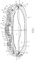
- the only figure shows a vertical section through a implantable infusion pump according to the invention.
- the infusion pump 1 shows an implantable infusion pump according to the invention 1 for the dosed delivery of medication into human beings Body shown.
- the infusion pump 1 is a disk-shaped one rotationally symmetrical body made of plastic and has a housing, which consists of a bowl-shaped chamber lower part 2, one bowl-shaped with opposite curvature executed upper chamber part 3, a union part 4 and a Septa holder 5 is composed.
- the interior is through a flexible membrane 6 in a first sub-chamber as a medication store 7 and in a second sub-chamber as a pressure chamber 8 divided for receiving a blowing agent.
- Annular groove 9 formed into a circumferential in a snap connection associated edge 10 of the upper chamber part 3 together engaged with an O-ring 11 and an edge 36 of the membrane 6 and is kept tight.
- a refill opening 12 is through a disc-shaped and pierceable central septum 13 tightly covered, the Refill opening 12 a refill space under the central septum 13 with a fixed plate as a needle stop and through openings to the drug store 7.
- a concentric annular groove 16 is formed on the inner and outer side wall each have a circumferential locking groove 17, 18th is appropriate.
- the ring-shaped septa holder 5 engages with the inner edge of the disc-shaped central septum 13 and with its outer edge the inner ring edge of the Ring septum 15.
- the septa holder 5 engages side by side lying ring webs 19, 20 into the annular groove 16, where locking lugs 21, 22 on the ring webs 19, 20 in the locking grooves 17, 18 intervene.
- the ring outer edge of the ring septum 15 is in a step-shaped Arrangement of a correspondingly shaped edge area of the throwing part 4 covered and against the upper chamber part 3 tightly jammed.
- a snap connection between the union part 4 and the chamber upper part 3 is provided, which consists of a rotating Locking groove 23 on the union part 4 and a circumferential locking lug 24 on the upper chamber part 3.
- a further annular groove 25 is formed, into which a circumferential one Latch 26 engages together with an inserted O-ring 27.
- the locking lug 26 represents the lower edge of the union part 4, this being the lateral region of the upper chamber part 3 and the outer lateral edge area of the lower chamber part 2 overlapping bell-shaped.
- the union part 4 supports itself (at high pressure load) on the upper chamber part 3 via the locking lug arrangement 24 and the ring septum 15 for Lower chamber part 2 down.
- annular space 28 for receiving an outlet reducing device 29 (here represented schematically as a section through a capillary) and an outlet catheter 30 is formed.
- connection 31, formed from the annular groove 9, the edge 10 and the O-ring 11, the connection 32, formed from the locking groove 23 and the locking lug 24 and the connection 33 from the locking groove 18 and the locking lugs 22 make main connections represents the under normal operational load Support the internal pressure loads that occur.
- connection 34 consisting of the annular groove 25, the locking lug 26 and the O-ring 27 and the connection 35 consisting of the locking groove 17 and the locking lugs 21 are secondary connections, which do not yet exist under normal operational stress or have only a small support function. Only when there is a pressure increase above normal operating pressure, especially at failure of the main connections 31, 32, 33 take over the secondary connections 34, 35 a support function.
- the main connections 31, 32, 33 are in constant engagement and represent the integrity of the implanted infusion pump safe under normal conditions.
- the secondary connections 34, 35 increasingly come into engagement. Thereby the voltages from the main connections 31, 32, 33 derived and divided into main and secondary connections on.
- the connection task is taken over by the secondary connection 34. Since at the same time there is a gap between the upper chamber part 3 and chamber lower part 2 arises, drug escapes into the Annulus 28 between the union part 4 and the upper chamber part 3, so that pressure and thus the load the connection decreases overall.
Landscapes
- Health & Medical Sciences (AREA)
- Hematology (AREA)
- Engineering & Computer Science (AREA)
- Anesthesiology (AREA)
- Biomedical Technology (AREA)
- Heart & Thoracic Surgery (AREA)
- Vascular Medicine (AREA)
- Life Sciences & Earth Sciences (AREA)
- Animal Behavior & Ethology (AREA)
- General Health & Medical Sciences (AREA)
- Public Health (AREA)
- Veterinary Medicine (AREA)
- Infusion, Injection, And Reservoir Apparatuses (AREA)
- Media Introduction/Drainage Providing Device (AREA)
Description
Claims (9)
- Implantierbare Infusionspumpe (1) zu dosierten Abgabe von Medikamenten in den menschlichen Körper,mit einer Pumpenkammer, die durch ein Kammerunterteil (2) und ein damit verbundenes Kammeroberteil (3) gebildet ist, wobeidie Pumpenkammer durch eine flexible Membran (6) in zwei Teilkammern unterteilt ist, deren erste Teilkammer vom Kammeroberteil (3) und der Membran (6) begrenzt ist und als Medikamentenspeicher (7) ausgebildet ist,das Kammeroberteil (3) eine Nachfüllöffnung (12) enthält, die durch wenigstens ein durchstechbares Septum (13) abgedichtet ist, das zwischen einem mit dem Kammeroberteil (3) verbundenen Septenhalterteil (5) und dem Kammeroberteil (3) verklemmt ist,der Medikamentenspeicher (7) über eine Auslaßöffnung und eine Auslaßreduziereinrichtung (29) mit einem Auslaßkatheter (30) verbunden ist, undderen zweite Teilkammer vom Kammerunterteil (2) und der Membran (6) begrenzt ist und als Druckkammer (8) zur Aufnahme eines Treibmittels ausgebildet ist,
dadurch gekennzeichnet,daß das Kammeroberteil (3), das Kammerunterteil (2) und das Septenhalterteil (5) derart ausgebildet sind, daß das Kammeroberteil (3) und das Kammerunterteil (2) sowie das Kammeroberteil (3) und das Septenhalterteil (5) über jeweils wenigstens zwei einander zugeordnete Verbindungen, von denen die eine als Hauptverbindung (31, 32, 33) und die andere als Nebenverbindung (34, 35) ausgeführt ist, in Eingriff sind,
wobei die Hauptverbindung (31, 32, 33) bei normaler betriebsmäßiger Belastung die auftretenden Innendruckbelastungen weitgehend abstützt und dabei in der Nebenverbindung (34, 35) noch keine oder nur eine geringe Abstützbelastung auftritt und bei einer durch eine Druckerhöhung über den normalen Betriebsdruck verursachten Verformung des Kammeroberteils (3), des Kammerunterteils (2) oder des Septenhalterteils (5) oder einer Verschiebung zwischen Kammeroberteil (3) und Kammerunterteil (2) sowie bei Versagen oder Nachgeben der Hauptverbindung (31, 32, 33) die Nebenverbindung (34, 35) entsprechend belastet wird und die Drucküberlast abstützt. - Implantierbare Infusionspumpe nach Anspruch, 1, dadurch gekennzeichnet, daß die einzelnen Verbindungen (31 - 35) durch Rastelemente als Rastverbindungen gebildet sind.
- Implantierbare Infusionspumpe nach Anspruch 2, dadurch gekennzeichnet, daß die Infusionspumpe (1) als scheibenförmiger Körper mit abgerundeten Scheibenrändern aus Kunststoff ausgeführt ist und die Rastverbindungen als Haupt- und Nebenverbindungen (31 - 35) mit konzentrisch liegenden umlaufenden Ringnuten und zugeordneten Ringstegen oder Rasthaken ausgeführt sind.
- Implantierbare Infusionspumpe nach Anspruch 3, dadurch gekennzeichnet,daß die Nachfüllöffung (12) zentrisch und das Septum als scheibenförmiges Zentralseptum (13) ausgebildet sind,daß am Kammeroberteil (3) eine konzentrische Ringnut (16) eingeformt ist, an deren innerer und äußerer Seitenwand jeweils umlaufend eine Rastnut (17, 18) angebracht ist,daß das Septenhalterteil (5) als Ring ausgebildet ist, der das Zentralseptum (13) randseitig übergreift und der zwei in die Ringnut (16) ragende, nebeneinander liegende Ringstege (19, 20) aufweist, die jeweils mit Rastnasen (21, 22) in die Rastnuten (17, 18) der Ringnut (16) eingreifen, wobei die zwei Verbindungen an den beiden Rastnuten (17, 18) eine Hauptverbindung (33) und eine zugeordnete Nebenyerbindung (35) darstellen.
- Implantierbare Infusionspumpe nach Anspruch 4, dadurch gekennzeichnet, daß die Verbindung an der äußeren Rastnut (18) die Hauptverbindung (33) und die Verbindung an der inneren Rastnut (19) die Nebenverbindung (35) bildet.
- Implantierbare Infusionspumpe nach einem der Ansprüche 2 bis 5, dadurch gekennzeichnet,daß am oberen, inneren Randbereich des schalenförmigen Kammerunterteils (2) eine Ringnut (9) vorgesehen ist, in die in einer Rastverbindung als Hauptverbindung (31) ein umlaufender zugeordneter Rand (10) des Kammeroberteils (3) zusammen mit einem O-Ring (11) und dem Rand (12) der Membran (6) eingerastet ist,daß am äußeren seitlichen Randbereich des Kammerunterteils (2) eine weitere Ringnut (25) vorgesehen ist, in die in einer Rastverbindung als zugeordnete Nebenverbindung (34) eine Rastnasenanordnung (26) eines ringförmigen Überwurfteils (4) eingreift, wobei das Überwurfteil (4) das Kammeroberteil (3) und den äußeren seitlichen Randbereich des Kammerunterteils (2) glockenförmig übergreift und sich am Kammeroberteil (3) abstützt.
- Implantierbare Infusionspumpe nach Anspruch 6, dadurch gekennzeichnet, daß zwischen einem äußeren Wandbereich des Kammeroberteils (3) und einem inneren Wandbereich des überwurfteils (4) ein Ringraum (28) gebildet ist.
- Implantierbare Infusionspumpe nach Anspruch 7, dadurch gekennzeichnet, daß der Ringraum zur Aufnahme der Auslaßreduziereinrichtung (29) und des Auslaßkatheters (30) gebildet ist.
- Implantierbare Infusionspumpe nach einem Ansprüche 6 bis 8, dadurch gekennzeichnet,daß an der Außenwand des Kammeroberteils (3) eine die Ringnut (16) umgebende Ringkammer (14) angeordnet ist, die von einem Ringseptum (15) abgedeckt und abgedichtet ist,daß der zur Ringnut (16) weisende Rand des Ringseptums (15) von einem äußeren Rand des ringförmigen Septenhalterteils (5) überdeckt und verklemmt ist,daß der ringäußere Rand des Ringseptums (15) von einem Randbereich des Überwurfteils (4) überdeckt und verklemmt ist, unddaß in diesem Randbereich des Überwurfteils (4) eine Rastverbindung (32) zwischen Überwurfteil (4) und Kammeroberteil (3) aus einer Rastnut (23) und Raststegen mit in die Rastnut (23) eingreifenden umlaufenden Rastnasen (24) vorgesehen ist, bevorzugt eine umlaufende Rastnut (23) am Überwurfteil (4) und eine umlaufende Rastnase (24) am Kammeroberteil (3), unddaß diese Rastverbindung (32) eine Hauptverbindung darstellt und daß die Rastverbindung (34) zwischen Kammerunterteil (2) und Überwurfteil (4) dazu eine Nebenverbindung bildet.
Applications Claiming Priority (2)
| Application Number | Priority Date | Filing Date | Title |
|---|---|---|---|
| DE4432991 | 1994-09-16 | ||
| DE4432991A DE4432991C1 (de) | 1994-09-16 | 1994-09-16 | Implantierbare Infusionspumpe |
Publications (2)
| Publication Number | Publication Date |
|---|---|
| EP0701831A1 EP0701831A1 (de) | 1996-03-20 |
| EP0701831B1 true EP0701831B1 (de) | 1998-11-11 |
Family
ID=6528368
Family Applications (1)
| Application Number | Title | Priority Date | Filing Date |
|---|---|---|---|
| EP95114614A Expired - Lifetime EP0701831B1 (de) | 1994-09-16 | 1995-09-17 | Implantierbare Infusionspumpe |
Country Status (5)
| Country | Link |
|---|---|
| US (1) | US5836915A (de) |
| EP (1) | EP0701831B1 (de) |
| JP (1) | JP3721219B2 (de) |
| DE (2) | DE4432991C1 (de) |
| ES (1) | ES2127980T3 (de) |
Families Citing this family (32)
| Publication number | Priority date | Publication date | Assignee | Title |
|---|---|---|---|---|
| DE19509634C1 (de) * | 1995-03-17 | 1996-03-28 | Fresenius Ag | Implantierbare Infusionspumpe |
| US5976109A (en) * | 1996-04-30 | 1999-11-02 | Medtronic, Inc. | Apparatus for drug infusion implanted within a living body |
| US6406455B1 (en) * | 1998-12-18 | 2002-06-18 | Biovalve Technologies, Inc. | Injection devices |
| US6589205B1 (en) | 1999-12-17 | 2003-07-08 | Advanced Bionica Corporation | Externally-controllable constant-flow medication delivery system |
| WO2001051109A1 (en) * | 2000-01-07 | 2001-07-19 | Biovalve Technologies, Inc. | Injection device |
| US6764472B1 (en) | 2000-01-11 | 2004-07-20 | Bard Access Systems, Inc. | Implantable refillable infusion device |
| US6572583B1 (en) * | 2000-04-28 | 2003-06-03 | Medtronic, Inc. | Bulkhead for implantable infusion device |
| US6719739B2 (en) * | 2000-08-30 | 2004-04-13 | Medtronic, Inc. | System and method for attaching upper and lower outer cases in an implantable drug pump |
| KR20030071780A (ko) * | 2000-11-30 | 2003-09-06 | 바이오밸브 테크놀로지스, 인코포레이티드 | 주입기 |
| US7776029B2 (en) * | 2001-01-30 | 2010-08-17 | The Alfred E. Mann Foundation For Scientific Research | Microminiature infusion pump |
| US7637897B2 (en) * | 2004-10-25 | 2009-12-29 | Codman Neuro Sciences Sarl | Implantable pump with integrated refill detection |
| US8915893B2 (en) | 2005-05-10 | 2014-12-23 | Palyon Medical (Bvi) Limited | Variable flow infusion pump system |
| US7637892B2 (en) | 2005-05-10 | 2009-12-29 | Palyon Medical (Bvi) Limited | Variable flow infusion pump system |
| US8211060B2 (en) | 2005-05-10 | 2012-07-03 | Palyon Medical (Bvi) Limited | Reduced size implantable pump |
| US8114055B2 (en) | 2005-05-10 | 2012-02-14 | Palyon Medical (Bvi) Limited | Implantable pump with infinitely variable resistor |
| US8034030B2 (en) * | 2005-05-25 | 2011-10-11 | Palyon Medical (Bvi) Limited | Multi-reservoir implantable pump with variable flow rate capabilities |
| US7708730B2 (en) * | 2006-01-30 | 2010-05-04 | Palyon Medical (Bvi) Limited | Template system for multi-reservoir implantable pump |
| MX2008010341A (es) * | 2006-02-09 | 2008-11-18 | Deka Products Lp | Sistemas y metodos adhesivos y perifericos para dispositivos medicos. |
| US7725272B2 (en) * | 2006-03-30 | 2010-05-25 | Codman Neuro Sciences, Sarl | Methods and devices for monitoring fluid of an implantable infusion pump |
| US8105269B2 (en) | 2008-10-24 | 2012-01-31 | Baxter International Inc. | In situ tubing measurements for infusion pumps |
| US8137083B2 (en) | 2009-03-11 | 2012-03-20 | Baxter International Inc. | Infusion pump actuators, system and method for controlling medical fluid flowrate |
| US8231598B2 (en) * | 2009-10-30 | 2012-07-31 | Palyon Medical (Bvi) Limited | Propellant bag improvement |
| US8382447B2 (en) | 2009-12-31 | 2013-02-26 | Baxter International, Inc. | Shuttle pump with controlled geometry |
| US8567235B2 (en) | 2010-06-29 | 2013-10-29 | Baxter International Inc. | Tube measurement technique using linear actuator and pressure sensor |
| US8876771B2 (en) | 2010-11-16 | 2014-11-04 | Palyon Medical (Bvi) Limited | Propellant pillow manufacturing technique |
| US8636693B2 (en) | 2011-04-27 | 2014-01-28 | Palyon Medical Corporation | Propellant pillow |
| US8568360B2 (en) | 2011-12-28 | 2013-10-29 | Palyon Medical (Bvi) Limited | Programmable implantable pump design |
| US8591456B2 (en) | 2011-12-28 | 2013-11-26 | Palyon Medical (Bvi) Limited | Multiple reservoir programmable pump |
| WO2014159866A1 (en) | 2013-03-13 | 2014-10-02 | Palyon Medical Corporation | Dual rate insulin pump |
| AU2016258179B2 (en) | 2015-05-06 | 2021-07-01 | Synagile Corporation | Pharmaceutical suspensions containing drug particles, devices for their administration, and methods of their use |
| IL270895B (en) * | 2019-11-25 | 2021-06-30 | Elad David | Infusion pump |
| EP3831426B1 (de) * | 2019-12-05 | 2025-07-09 | Heraeus Medical GmbH | Vorrichtung zur lokalen applikation von pharmazeutischen fluiden |
Family Cites Families (11)
| Publication number | Priority date | Publication date | Assignee | Title |
|---|---|---|---|---|
| US3731681A (en) * | 1970-05-18 | 1973-05-08 | Univ Minnesota | Implantable indusion pump |
| US3951147A (en) * | 1975-04-07 | 1976-04-20 | Metal Bellows Company | Implantable infusate pump |
| NL8400489A (nl) * | 1983-11-23 | 1985-06-17 | Cordis Corp | Handbedienbare, in het lichaam implanteerbare doseerinrichting voor een stroombaar medikament. |
| US4820273A (en) * | 1988-03-01 | 1989-04-11 | Eaton Corporation | Implantable medication infusion device and bolus generator therefor |
| AT391416B (de) * | 1988-06-23 | 1990-10-10 | Annemarie Schloegl Ges M B H M | Septum fuer implantierbare vorrichtungen zur abgabe von wirkstoffen |
| FR2645029B1 (fr) * | 1989-03-28 | 1997-09-12 | Cordis Sa | Membrane de reservoir implantable sous la peau d'un patient |
| DE3915251A1 (de) * | 1989-05-10 | 1990-11-22 | Annemarie Schloegl Ges M B H | Implantierbare vorrichtung zur dosierten abgabe von medikamenten in den menschlichen koerper |
| US5167633A (en) * | 1990-11-29 | 1992-12-01 | Pacesetter Infusion, Ltd. | Liquid-vapor pressure reservoir for medication infusion pump |
| US5306257A (en) * | 1992-05-04 | 1994-04-26 | Prime Medical Products, Inc. | Drug infuser |
| US5281111A (en) * | 1992-12-23 | 1994-01-25 | Abbott Laboratories | Cartridge for drug infusion pump |
| US5578005A (en) * | 1993-08-06 | 1996-11-26 | River Medical, Inc. | Apparatus and methods for multiple fluid infusion |
-
1994
- 1994-09-16 DE DE4432991A patent/DE4432991C1/de not_active Expired - Fee Related
-
1995
- 1995-09-17 DE DE59504201T patent/DE59504201D1/de not_active Expired - Lifetime
- 1995-09-17 ES ES95114614T patent/ES2127980T3/es not_active Expired - Lifetime
- 1995-09-17 EP EP95114614A patent/EP0701831B1/de not_active Expired - Lifetime
- 1995-09-18 US US08/529,776 patent/US5836915A/en not_active Expired - Lifetime
- 1995-09-18 JP JP26357295A patent/JP3721219B2/ja not_active Expired - Fee Related
Also Published As
| Publication number | Publication date |
|---|---|
| JPH08224301A (ja) | 1996-09-03 |
| EP0701831A1 (de) | 1996-03-20 |
| JP3721219B2 (ja) | 2005-11-30 |
| DE59504201D1 (de) | 1998-12-17 |
| DE4432991C1 (de) | 1995-10-26 |
| US5836915A (en) | 1998-11-17 |
| ES2127980T3 (es) | 1999-05-01 |
Similar Documents
| Publication | Publication Date | Title |
|---|---|---|
| DE4432991C1 (de) | Implantierbare Infusionspumpe | |
| DE19509632C1 (de) | Implantierbare Infusionspumpe | |
| EP0347743B1 (de) | Septum für implantierbare Vorrichtungen zur Abgabe von Wirkstoffen | |
| EP0401515B1 (de) | Implantierbare Vorrichtung zur dosierten Abgabe von Medikamenten in den menschlichen Körper | |
| EP0732113B1 (de) | Implantierbare Infusionspumpe | |
| DE69104143T2 (de) | Infusionsvorrichtung für Flüssigkeiten. | |
| DE4335099C2 (de) | Vorrichtung zum Beschränken des perkutanen Zuganges zu einem Septum | |
| EP0582163B1 (de) | Implantierbare Vorrichtung | |
| DE69839370T2 (de) | Einlass für Medikamenteninfusionspumpe | |
| DE60028948T2 (de) | Nadellose zugangsvorrichtung | |
| EP0531809B1 (de) | Implantierbare Vorrichtung zur Abgabe von Wirkstoffen | |
| DE69621544T2 (de) | Wiederverschliessbare Behälteranordnung mit Membrane und Schieber | |
| DE69317422T2 (de) | Medizinische kupplungsstelle | |
| DE69100844T2 (de) | Programmierbare ventilpumpe. | |
| EP0882466B1 (de) | Vorrichtung zur dosierten Verabreichung einer Medikamentflüssigkeit | |
| DE69619450T2 (de) | Wiederverschliessbare, durch eine medizinische Abgabevorrichtung aktivierbare, Behälteranordnung | |
| DE69206354T2 (de) | Arzneimittelbehälter und System aus zwei Behältern zur Anwendung in einer Flüssigkeitstherapie. | |
| DE68920049T2 (de) | Implantierbare infusionsvorrichtung. | |
| DE69517169T2 (de) | Vorrichtung zur abgabe von medikamenten | |
| DE60004082T2 (de) | Einsatzbereite verbindungsvorrichtung | |
| DE10126393A1 (de) | Medikamentenpumpe mit Verstärkungsrillen | |
| DE10020689A1 (de) | System zum Schutz implantierbarer Medikamenten-Abgabegeräte vor einem Überfüllen | |
| EP1567215B1 (de) | Vorrichtung zum verschrauben mediumfuehrender gewindeverbindungen, insbesondere luer-lock-verbindungen | |
| DE3528878A1 (de) | Intraperitonealkatheter fuer die zufuehrung fluessiger arzneimittel, insbesondere von insulin | |
| DE2040072B2 (de) | Injektionsspritze |
Legal Events
| Date | Code | Title | Description |
|---|---|---|---|
| PUAI | Public reference made under article 153(3) epc to a published international application that has entered the european phase |
Free format text: ORIGINAL CODE: 0009012 |
|
| 17P | Request for examination filed |
Effective date: 19951229 |
|
| AK | Designated contracting states |
Kind code of ref document: A1 Designated state(s): DE ES FR GB IT |
|
| 17Q | First examination report despatched |
Effective date: 19961129 |
|
| GRAG | Despatch of communication of intention to grant |
Free format text: ORIGINAL CODE: EPIDOS AGRA |
|
| GRAG | Despatch of communication of intention to grant |
Free format text: ORIGINAL CODE: EPIDOS AGRA |
|
| GRAH | Despatch of communication of intention to grant a patent |
Free format text: ORIGINAL CODE: EPIDOS IGRA |
|
| GRAH | Despatch of communication of intention to grant a patent |
Free format text: ORIGINAL CODE: EPIDOS IGRA |
|
| GRAA | (expected) grant |
Free format text: ORIGINAL CODE: 0009210 |
|
| AK | Designated contracting states |
Kind code of ref document: B1 Designated state(s): DE ES FR GB IT |
|
| GBT | Gb: translation of ep patent filed (gb section 77(6)(a)/1977) |
Effective date: 19981112 |
|
| REF | Corresponds to: |
Ref document number: 59504201 Country of ref document: DE Date of ref document: 19981217 |
|
| ITF | It: translation for a ep patent filed | ||
| ET | Fr: translation filed | ||
| REG | Reference to a national code |
Ref country code: ES Ref legal event code: FG2A Ref document number: 2127980 Country of ref document: ES Kind code of ref document: T3 |
|
| PLBE | No opposition filed within time limit |
Free format text: ORIGINAL CODE: 0009261 |
|
| STAA | Information on the status of an ep patent application or granted ep patent |
Free format text: STATUS: NO OPPOSITION FILED WITHIN TIME LIMIT |
|
| 26N | No opposition filed | ||
| REG | Reference to a national code |
Ref country code: GB Ref legal event code: IF02 |
|
| REG | Reference to a national code |
Ref country code: GB Ref legal event code: 732E |
|
| REG | Reference to a national code |
Ref country code: ES Ref legal event code: PC2A |
|
| REG | Reference to a national code |
Ref country code: ES Ref legal event code: PC2A |
|
| REG | Reference to a national code |
Ref country code: FR Ref legal event code: TP |
|
| REG | Reference to a national code |
Ref country code: ES Ref legal event code: PC2A |
|
| REG | Reference to a national code |
Ref country code: FR Ref legal event code: CD |
|
| PGFP | Annual fee paid to national office [announced via postgrant information from national office to epo] |
Ref country code: ES Payment date: 20100922 Year of fee payment: 16 |
|
| PGFP | Annual fee paid to national office [announced via postgrant information from national office to epo] |
Ref country code: IT Payment date: 20100918 Year of fee payment: 16 Ref country code: FR Payment date: 20100920 Year of fee payment: 16 |
|
| PGFP | Annual fee paid to national office [announced via postgrant information from national office to epo] |
Ref country code: GB Payment date: 20100809 Year of fee payment: 16 |
|
| PGFP | Annual fee paid to national office [announced via postgrant information from national office to epo] |
Ref country code: DE Payment date: 20100930 Year of fee payment: 16 |
|
| GBPC | Gb: european patent ceased through non-payment of renewal fee |
Effective date: 20110917 |
|
| PG25 | Lapsed in a contracting state [announced via postgrant information from national office to epo] |
Ref country code: IT Free format text: LAPSE BECAUSE OF NON-PAYMENT OF DUE FEES Effective date: 20110917 |
|
| REG | Reference to a national code |
Ref country code: FR Ref legal event code: ST Effective date: 20120531 |
|
| REG | Reference to a national code |
Ref country code: DE Ref legal event code: R119 Ref document number: 59504201 Country of ref document: DE Effective date: 20120403 |
|
| PG25 | Lapsed in a contracting state [announced via postgrant information from national office to epo] |
Ref country code: DE Free format text: LAPSE BECAUSE OF NON-PAYMENT OF DUE FEES Effective date: 20120403 |
|
| PG25 | Lapsed in a contracting state [announced via postgrant information from national office to epo] |
Ref country code: GB Free format text: LAPSE BECAUSE OF NON-PAYMENT OF DUE FEES Effective date: 20110917 Ref country code: FR Free format text: LAPSE BECAUSE OF NON-PAYMENT OF DUE FEES Effective date: 20110930 |
|
| REG | Reference to a national code |
Ref country code: ES Ref legal event code: FD2A Effective date: 20130417 |
|
| PG25 | Lapsed in a contracting state [announced via postgrant information from national office to epo] |
Ref country code: ES Free format text: LAPSE BECAUSE OF NON-PAYMENT OF DUE FEES Effective date: 20110918 |