EP0701507B1 - Process for determining and using the quantity of filling press material in solid-liquid separation with a filter press - Google Patents
Process for determining and using the quantity of filling press material in solid-liquid separation with a filter press Download PDFInfo
- Publication number
- EP0701507B1 EP0701507B1 EP95911183A EP95911183A EP0701507B1 EP 0701507 B1 EP0701507 B1 EP 0701507B1 EP 95911183 A EP95911183 A EP 95911183A EP 95911183 A EP95911183 A EP 95911183A EP 0701507 B1 EP0701507 B1 EP 0701507B1
- Authority
- EP
- European Patent Office
- Prior art keywords
- yield
- filling
- working point
- pressing
- efficiency
- Prior art date
- Legal status (The legal status is an assumption and is not a legal conclusion. Google has not performed a legal analysis and makes no representation as to the accuracy of the status listed.)
- Expired - Lifetime
Links
Images


Classifications
-
- B—PERFORMING OPERATIONS; TRANSPORTING
- B30—PRESSES
- B30B—PRESSES IN GENERAL
- B30B9/00—Presses specially adapted for particular purposes
- B30B9/02—Presses specially adapted for particular purposes for squeezing-out liquid from liquid-containing material, e.g. juice from fruits, oil from oil-containing material
- B30B9/04—Presses specially adapted for particular purposes for squeezing-out liquid from liquid-containing material, e.g. juice from fruits, oil from oil-containing material using press rams
- B30B9/047—Control arrangements
-
- B—PERFORMING OPERATIONS; TRANSPORTING
- B30—PRESSES
- B30B—PRESSES IN GENERAL
- B30B9/00—Presses specially adapted for particular purposes
- B30B9/02—Presses specially adapted for particular purposes for squeezing-out liquid from liquid-containing material, e.g. juice from fruits, oil from oil-containing material
- B30B9/04—Presses specially adapted for particular purposes for squeezing-out liquid from liquid-containing material, e.g. juice from fruits, oil from oil-containing material using press rams
-
- B—PERFORMING OPERATIONS; TRANSPORTING
- B30—PRESSES
- B30B—PRESSES IN GENERAL
- B30B9/00—Presses specially adapted for particular purposes
- B30B9/02—Presses specially adapted for particular purposes for squeezing-out liquid from liquid-containing material, e.g. juice from fruits, oil from oil-containing material
- B30B9/22—Presses specially adapted for particular purposes for squeezing-out liquid from liquid-containing material, e.g. juice from fruits, oil from oil-containing material using a flexible member, e.g. diaphragm, urged by fluid pressure
Definitions
- the invention relates to a method for determining and Use of the filling quantities of pressed material in the solid-liquid separation with a filter press comprising one Press room in which liquid under the influence of a press element acted upon by compressive force several successive lifting operations from the pressed material is squeezed, whereby in the course of a filling phase of Separation process in each lifting a quantity in the Press room is introduced.
- Prefill quantity The same conditions apply here as with the total filling quantity. Too small or too big The prefill quantity influences the yield / performance behavior very negative.
- the invention is therefore based on the object specified problems through an optimized procedure for Determination and use of the filling quantities of pressed material at to fix a filter press.
- this object is achieved achieved through the following steps: 1) it is under measurement a filling and pressing process of performance and yield executed, which in the yield / performance diagram a first operating point with known performance and Yield leads; 2) for at least one subsequent one second filling and pressing process, which in the yield / performance diagram leads to a second working point at least one process variable for the second operating point set and then using relationships for the changes in performance and yield of solid-liquid separation in the filling and pressing processes under Interposition of a fictitious working point Filling quantity determined and used, which is required so that a maximum product of Yield and performance results, the transition from the first Working point to the fictitious working point by a pure Filling takes place and the transition from fictional Working point to the second working point by a pure one Pressing takes place and it is assumed that the rectilinear connections of those working points which differ by a pure pressing process, differ in Yield / performance diagram in a common Working point with maximum yield and vanishing Cut power or are parallel to each other.
- Fig. 1 shows schematically a horizontal Filter piston press of known type. It comprises one Press cover 11 is located inside the press cover 11 a plunger 6, which is attached to a piston rod 14 is.
- the piston rod 14 is in a hydraulic Cylinder movably supported and leads over the plunger 6 the pressing operations.
- the press jacket 11 is about a closable filling opening by means of a pump 8 the pressed material 7 introduced, which a variety of not penetrates with drainage elements shown.
- the drainage elements guide the liquid during the pressing process Phase of the material to be pressed 7 under the pressure of Press plunger 6 into a drain line 10 to the outside.
- a drain line 10 to the outside.
- At the pressed material can be fruit and the liquid phase around fruit juice.
- the "priming" process ends as soon as the Press plunger 6 no longer at position HS reached. Then in a subsequent step only filled in discontinuous phases, each start withdrawing the plunger 6. It is first ensured by a filling control that the Press plunger 6 always the same for each lifting operation HS lying end position reached.
- the plunger 6 also reaches progressive filling of the press room positions which move further and further away from HS.
- the Filling control for every lifting and pressing process the yield or the performance of the pressing process constant remains. Reaches the plunger 6 during its advance the position HE, so in a subsequent step then back to the constant end position of the plunger 6 driven until the desired total amount of Press material is filled and the other press strokes only still take place without filling processes F.
- Fig. 2 shows in a representation similar to Fig. 1, in which same reference number on same functions indicate separate filling and pressing processes.
- An operating point denoted by 1 in FIG. 3 corresponds a current operating state of the press, like him within a sequence of individual pressings of FIG. 1 and 2 described type immediately after the end of a Lifting process occurs.
- the plunger 6 is at Working point 1 is still in the pressing position, the working pressure but has already been dismantled. The previous one The lifting process started at operating point 1 '.
- the working points 1 ', 1 differ only in this lifting process. If you carry out a certain filling quantity in working point 1 Pressed material too, so working point 1 goes into one Working point 3 'above, the power L increases and the yield A decreases.
- Working points 1, 3 ' differ only in this filling process.
- FIG. 4 shows a straight course of the pressing characteristics in the Course of several pure pressing processes. It has Pressed material due to a low total filling quantity Condition a). In comparison, for a state b) the Pressed goods with a larger total filling quantity in the final state another straight line.
- the extended courses a) and b) run through one under idealized conditions common intersection A0 with the yield axis, corresponding to a performance value of zero. In practice it can this intersection A0 its location during processing change a batch of pressed material.
- Fig. 5 shows the power yield comparative Combinations with different regulations of the Press operations can be achieved.
- R1 Pre-filling process
- L constant power L
- Yield A shows the pressing process R2 a regulation with the The goal is constant performance with almost sufficient Refill performance.
- R3 a pressing process without refill.
- the course b shows a pressing process with insufficient refill performance.
- the course a finally shows three parts, which one after the other constant end position of the pressing element for everyone Press stroke, with constant yield and finally after End of filling.
- Fig. 7 shows the course in the yield / performance diagram a single pressing process, in which between the Working points 1 at the beginning and 4 at the end quantity of pressed material supplied is determined so that the Yield is kept constant. Another one Pressability of the goods can also be a point 4 result in greater power to the right of point 1.
- FIG. 8 shows the course in the yield / performance diagram a pressing process in which during a Pre-fill R1 and several piston strokes comprehensive pre-pressing process is no longer refilled. This process was described in relation to FIG. 2. To the Prepress closes a non-pressing Refill process that leads from point 4 to point 3 '. At the transition from point 3 'to point 4' follow again several pressing processes without refilling. The one for the pressure-free refilling process is used working time through a transition to a virtual working point 1 ' shown.
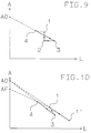
- Fig. 9 shows how in the yield / performance diagram of the Influence of a refill quantity supplied by a theoretical consideration can be captured. Similar to already described for FIG. 3, corresponds to the operating point 1 the current operating status immediately after the end of a single previous press stroke. The plunger 6 (Fig. 1) is still in the pressing position HS, the pressing pressure but already dismantled. Due to the refill quantity Press residues are diluted and the yield is reduced. In a virtually no time consumption through pure filling If you reach point 2, the yield will decrease, while performance remains the same.
- G1 denotes the quantity of pressed material supplied up to point 1
- G2 the quantity supplied up to point 2 and A1 and A2 the yields in points 1 and 2
- A2 A1 (G1 / G2)
- Fig. 10 shows similar to Figs. 3 and 9 in a yield / performance diagram the working points that arise if for the second, through a single filling and Lifting process from working point 1 reached working point 4 the condition specifies that the associated values of Yield A4 and power L4 of this operating point 4 one Point 4 on the straight line connecting the first Working point 1 and a working point AF on the Define the yield axis, which is a fixed maximum theoretical yield value for the material to be pressed corresponds.
Abstract
Description
Die Erfindung betrifft ein Verfahren zur Bestimmung und Verwendung der Füllmengen von Pressgut bei der Fest-Flüssigtrennung mit einer Filterpresse umfassend einen Pressraum, in welchem Flüssigkeit unter Einwirkung eines mit Druckkraft beaufschlagten Presselementes mittels mehrerer aufeinander folgender Hubvorgänge vom Pressgut abgepresst wird, wobei im Verlauf einer Füllphase des Trennvorganges in jedem Hubvorgang eine Füllmenge in den Pressraum eingebracht wird.The invention relates to a method for determining and Use of the filling quantities of pressed material in the solid-liquid separation with a filter press comprising one Press room in which liquid under the influence of a press element acted upon by compressive force several successive lifting operations from the pressed material is squeezed, whereby in the course of a filling phase of Separation process in each lifting a quantity in the Press room is introduced.
Bei derartigen diskentinuierlichen Filterpressen wird unter Einwirkung eines Pressdruckes der flüssige Anteil des Pressgutes über Filter nach aussen abgeleitet. Dabei wird der Pressdruck direkt über eine starre Druckplatte oder pneumatisch oder hydraulisch über eine flexible Membran auf das Pressgut aufgebracht. Bei Beginn der Pressgutzuführung stellt sich die Frage, welche Menge in den Pressraum vorgefüllt werden muss, damit ein für eine erste Abpressung ausreichendes Presspolster vorliegt. Dabei ist zu beachten, dass bei vorgefahrener Druckplatte oder Membrane das Verhältnis zwischen wirksamer Filterfläche und momentanem Pressraumvolumen grösser ist als bei zurückgezogenem Presselement.In such discontinent filter presses is under Exposure to a pressing pressure the liquid portion of the Pressed material is discharged to the outside via a filter. Doing so the pressing pressure directly via a rigid pressure plate or pneumatically or hydraulically via a flexible membrane the pressed material applied. At the beginning of the feed supply the question arises, how much in the press room must be pre-filled so that a first impression there is sufficient press cushion. It should be noted, that with the pressure plate or membrane in front of it Relationship between effective filter area and current one Bale volume is greater than when withdrawn Pressing element.
Für den nachfolgenden weiteren Füllvorgang stellt sich die Frage, welche Menge pro Hub des Presselementes nachgefüllt werden soll, damit ein günstiges Entsaftungsverhalten erreicht wird. Hinsichtlich der zu verarbeitenden Pressgüter ergeben sich bei organischen und anorganischen Materialien unterschiedliche Probleme. Für organische Materialien ist typisch, dass sich die Verarbeitbarkeit in der Presse (Pressbarkeit) von Charge zu Charge stark ändert. Eine dementsprechende bekannte fortlaufende Anpassung der Prozessparameter zur Erzielung annähernd optimaler Pressablaufe von Hand setzt beim Bedienungspersonal viel Erfahrung und eine weitgehend kontinuierliche Überwachung der Presse beim Füllvorgang voraus.For the subsequent further filling process, the Question of how much is refilled per stroke of the pressing element should be, so a favorable juicing behavior is achieved. With regard to the to be processed Pressed goods result from organic and inorganic Materials different problems. For organic It is typical that the workability is in materials the press (pressability) from batch to batch changes. A corresponding known continuous Approximate adjustment of the process parameters to achieve optimal pressing processes by hand Operators a lot of experience and largely continuous monitoring of the press during the filling process ahead.
Bekannte Versuche, erforderliche Anpassungen der Prozessparameter zu automatisieren sind ohne Erfolg geblieben. Eine brauchbare modellmässige Erfassung der Vorgänge beim Pressvorgang ist bisher nicht gelungen.Known attempts, necessary adjustments to the Automating process parameters is unsuccessful remained. A usable model-based recording of the Processes in the pressing process have so far not been successful.
Sehr hohe Anforderungen an die Bedienungsperson stellt vor allem das Befüllen der Fressen. Bei einer horizontalen Filterpresse für Fruchtmaterial sind beispielsweise folgende Sollwertvorgaben erforderlich:Very high demands on the operator all the stuffing of the food. With a horizontal one Filter presses for fruit material are for example The following setpoint specifications are required:
Totale Füllmenge. Diese ist stark abhängig von der Pressbarkeit des Pressgutes. Schlecht pressbare Güter erlauben nur kleine, während gut pressbare Güter grosse Totalfüllmengen zulassen.Total filling quantity. This is strongly dependent on the Pressability of the material to be pressed. Goods that are difficult to press allow only small goods that are easy to press and large ones Allow total fill quantities.
Vorfüllmenge. Hierbei gelten die gleichen Bedingungen, wie bei der Totalfüllmenge. Eine zu kleine oder zu grosse Vorfüllmenge beeinflusst das Ausbeute/ Leistungsverhalten sehr negativ.Prefill quantity. The same conditions apply here as with the total filling quantity. Too small or too big The prefill quantity influences the yield / performance behavior very negative.
Füllmenge pro Kolbenhub. Nach Ende der Vorfüllung wird bei bekannten Pressverfahren pro Kolbenhub einer Filterkolbenpresse eine definierte Pressgutmenge nachgefüllt. Diese schubweisen Füllimpulse erfolgen so lange, bis die vorgegebene Totalfüllmenge als Summe erreicht ist. Auch die passende Wahl dieser Füllmenge als Prozessgrösse ist stark von der Pressbarkeit des Gutes abhängig.Filling quantity per piston stroke. At the end of the pre-filling, known pressing process per piston stroke one Filter piston press a defined amount of material to be pressed refilled. This batch-wise filling impulses take place in this way long until the specified total filling quantity as a sum is reached. The right choice of this filling quantity as Process size is strongly dependent on the compressibility of the goods dependent.
Insgesamt ergibt sich, dass die Pressergebnisse je nach Können und Erfahrung der Bedienungsperson der Presse sehr unterschiedlich ausfallen, weil manuelle Vorgaben der Prozessparameter aufgrund der notwendigen Schätzungen das Ausbeute/ Leistungsverhalten der Pressvorgänge selten optimal ausfallen lassen.Overall, it follows that the press results depend on Skill and experience of the press operator very much turn out differently, because the manual specifications of the Process parameters based on the necessary estimates Yield / performance behavior of the pressing processes rarely let it turn out optimally.
Der Erfindung liegt deshalb die Aufgabe zugrunde, die angegebenen Probleme durch ein optimiertes Verfahren zur Bestimmung und Verwendung der Füllmengen von Pressgut bei einer Filterpresse zu beheben.The invention is therefore based on the object specified problems through an optimized procedure for Determination and use of the filling quantities of pressed material at to fix a filter press.
Gemäss der Erfindung wird die Lösung dieser Aufgabe erreicht durch folgende Schritte: 1) es wird unter Messung von Leistung und Ausbeute ein Füll- und Pressvorgang ausgeführt, welcher im Ausbeute/ Leistungsdiagramm zu einem ersten Arbeitspunkt mit bekannter Leistung und Ausbeute führt; 2) für mindestens einen nachfolgenden zweiten Füll- und Pressvorgang, welcher im Ausbeute/ Leistungsdiagramm zu einem zweiten Arbeitspunkt führt, wird mindestens eine Prozessgrösse für den zweiten Arbeitspunkt festgelegt und dann unter Verwendung von Beziehungen für die Änderungen von Leistung und Ausbeute der Fest-Flüssigtrennung bei den Füll- und Pressvorgängen unter Zwischenschaltung eines fiktiven Arbeitspunktes eine Füllmenge bestimmt und verwendet, welche erforderlich ist, damit sich bei dem Trennvorgang ein maximales Produkt von Ausbeute und Leistung ergibt, wobei der Übergang vom ersten Arbeitspunkt zum fiktiven Arbeitspunkt durch einen reinen Füllvorgang erfolgt und der Übergang vom fiktiven Arbeitspunkt zum zweiten Arbeitspunkt durch einen reinen Pressvorgang erfolgt und vorausgesetzt wird, dass die geradlinigen Verbindungen derjenigen Arbeitspunkte, welche sich durch einen reinen Pressvorgang unterscheiden, sich im Ausbeute/ Leistungsdiagramm in einem gemeinsamen Arbeitspunkt mit maximaler Ausbeute und verschwindender Leistung schneiden oder zueinander parallel sind.According to the invention, this object is achieved achieved through the following steps: 1) it is under measurement a filling and pressing process of performance and yield executed, which in the yield / performance diagram a first operating point with known performance and Yield leads; 2) for at least one subsequent one second filling and pressing process, which in the yield / performance diagram leads to a second working point at least one process variable for the second operating point set and then using relationships for the changes in performance and yield of solid-liquid separation in the filling and pressing processes under Interposition of a fictitious working point Filling quantity determined and used, which is required so that a maximum product of Yield and performance results, the transition from the first Working point to the fictitious working point by a pure Filling takes place and the transition from fictional Working point to the second working point by a pure one Pressing takes place and it is assumed that the rectilinear connections of those working points which differ by a pure pressing process, differ in Yield / performance diagram in a common Working point with maximum yield and vanishing Cut power or are parallel to each other.
Vorteilhafte Ausführungsformen des Verfahrens sind den Patentansprüchen zu entnehmen.Advantageous embodiments of the method are Find patent claims.
Ausführungsbeispiele der Erfindung sind in der folgenden
Beschreibung und den Figuren der Zeichnung näher erläutert.
Es zeigen:
Show it:
Fig. 1 zeigt schematisch eine horizontale
Filterkolbenpresse bekannter Art. Sie umfasst einen
Pressmantel 11. Innerhalb des Pressmantels 11 befindet sich
ein Presskolben 6, der an einer Kolbenstange 14 befestigt
ist. Die Kolbenstange 14 ist in einem hydraulischen
Zylinder beweglich gelagert und führt über den Presskolben
6 die Pressvorgänge aus. In den Pressmantel 11 wird über
eine verschliessbare Einfüllöffnung mittels einer Pumpe 8
das Pressgut 7 eingebracht, welches eine Vielzahl von nicht
mit dargestellten Drainageelementen durchdringt.Fig. 1 shows schematically a horizontal
Filter piston press of known type. It comprises one
Die Drainageelemente leiten beim Pressvorgang die flüssige
Phase des Pressgutes 7 unter der Druckwirkung des
Presskolbens 6 in eine Abflussleitung 10 nach aussen. Bei
dem Pressgut kann es sich um Obst handeln und bei der
flüssigen Phase somit um Obstsaft.The drainage elements guide the liquid during the pressing process
Phase of the material to be pressed 7 under the pressure of
Press plunger 6 into a
Der bekannte Verfahrensablauf des Pressens ist im Normalfall folgender: The known procedure of pressing is in Usually the following:
-
Der Presskolben 6 wird zurückgezogen und gleichzeitig
wird das Pressgut 7 über die Öffnung eingefüllt.The
plunger 6 is withdrawn and at the same time the material to be pressed 7 is filled in through the opening.
- Die ganze in Fig. 1 gezeigte Presseinheit wird um die Mittelachse rotiert,The whole press unit shown in Fig. 1 is around the Center axis rotates,
-
Der Presskolben 6 wird unter Druck vorgefahren,The
plunger 6 is advanced under pressure, - Der Saft wird durch Pressen vom Pressgut abgetrennt,The juice is separated from the pressed material by pressing,
- Der Pressdruck wird abgestellt.The pressure is turned off.
-
Der Presskolben 6 wird unter Rotation der ganzen in
Fig. 1 gezeigten Presseinheit zurückgezogen, wobei das
zurückgebliebene Pressgut aufgelockert und aufgerissen
wird.The
plunger 6 is rotated all over Fig. 1 retracted press unit, the leftover pressed material loosened up and torn open becomes.
- Die Verfahrensschritte Pressen und Auflockern werden als Abpressungen pro Charge Pressgut mehrfach wiederholt, bis ein erwünschter End- Auspresszustand erreicht ist.The process steps of pressing and loosening are called Repetitions per batch of pressed material are repeated several times until a desired final squeezing condition has been reached.
-
Die Pressrückstände werden durch Öffnen des Pressmantels
11 entleert.The press residues are opened by opening the
press jacket 11 emptied.
Der Verfahrensablauf bei einer Filterkolbenpresse wird
anhand der Fig. 1 näher beschrieben. Dort sind neben dem
schon beschriebenen Schema der Filterkolbenpresse
zugehörige graphische Darstellungen gezeigt, welche die
Kolbenhube zwischen den Positionen HM und HS und die
Füllfunktion F über der Zeit t zeigen. Wie durch die Zeit-Diagramme
neben dem Pressmantel 11 dargestellt, wird zu
Beginn das Pressgut 7 kontinuierlich mittels der Pumpe 8
über eine Öffnung dem Pressraum zugeführt. Dabei wird der
Presskolben 6, ausgehend von einer Position HM bewegt und
bei Erreichen der Position HS sogleich wieder in seine
Ausgangsposition HM zurückgezogen. Dieser Vorgang wird
mehrfach wiederholt. Ein mit F bezeichneter Balken zeigt
den gleichzeitig ablaufenden kontinuierlichen Vorgang
"Vorfüllen".The procedure for a filter piston press is
described with reference to FIG. 1. There are next to that
filter piston press scheme already described
associated graphical representations shown which the
Piston stroke between the positions HM and HS and the
Show filling function F over time t. As through the time charts
shown next to the
Der Vorgang "Vorfüllen" wird beendet, sobald der
Presskolben 6 bei seinem Vorlauf die Position HS nicht mehr
erreicht. Dann wird in einem nachfolgenden Schritt nur noch
in diskontinuierlichen Phasen eingefüllt, welche jeweils
mit dem Rückzug des Presskolbens 6 beginnen. Dabei ist
zunächst durch eine Füllregelung dafür gesorgt, dass der
Presskolben 6 bei jedem Hubvorgang immer eine gleiche, vor
HS liegende Endposition erreicht.The "priming" process ends as soon as the
Bei einem weiteren Schritt erreicht der Presskolben 6 mit
fortschreitender Füllung des Pressraumes Positionen, welche
sich von HS immer weiter entfernen. Dabei sorgt die
Füllregelung dafür, dass bei jedem Hub- und Pressvorgang
die Ausbeute oder die Leistung des Pressvorganges konstant
bleibt. Erreicht dabei der Presskolben 6 bei seinem Vorlauf
die Position HE, so wird in einem nachfolgenden Schritt
dann wieder auf konstante Endposition des Presskolbens 6
gefahren, bis insgesamt die gewünschte Gesamtmenge des
Pressgutes eingefüllt ist und die weiteren Presshübe nur
noch ohne Füllvorgänge F erfolgen.In a further step, the
Fig. 2 zeigt in einer der Fig. 1 ähnlichen Darstellung, in
welcher gleiche Bezugszeichen auf gleiche Funktionen
hinweisen, voneinander getrennte Füll- und Pressvorgänge.
Vor Beginn der am Balken F erkennbaren "Vorfüllung" läuft
der Presskolben 6 auf eine Endposition HS vor. Beim
anschliessenden Vorfüllen wird der Presskolben 6 nicht
verriegelt, er wird durch den Einpumpdruck auf eine
Position HM zurückgeschoben, ohne Presshübe auszuüben. Nach
Ende des Vorfüllens erfolgt mittels mehrerer Hübe eine
"Vorpressung" ohne Füllvorgänge, an welche sich wieder eine
Nachfüllung ohne Presshübe anschliesst, sobald der
Presskolben 6 eine Hubposition HN überschreitet.
Schliesslich erfolgen die weiteren Presshübe nur noch ohne
Füllvorgänge F. Fig. 2 shows in a representation similar to Fig. 1, in
which same reference number on same functions
indicate separate filling and pressing processes.
Before the "pre-filling" recognizable by the bar F begins
the
Die soweit als Beispiele beschriebenen unterschiedlich
geregelten Pressvorgänge lassen sich in einem für
grundsätzliche Betrachtungen geeigneten Ausbeute/ Leistungsdiagramm
darstellen, wie es Fig. 3 zeigt. Dabei
gelten die Vereinbarungen
Ein in Fig. 3 mit 1 bezeichneter Arbeitspunkt entspricht
einem momentanen Betriebszustand der Presse, wie er
innerhalb einer Folge von Einzelpressungen der zu Fig. 1
und 2 beschriebenen Art unmittelbar nach dem Ende eines
Hubvorganges auftritt. Der Presskolben 6 befindet sich beim
Arbeitspunkt 1 noch in der Pressposition, der Arbeits-Pressdruck
ist aber schon abgebaut. Der vorhergehende
Hubvorgang begann im Arbeitspunkt 1'. Die Arbeitspunkte 1',
1 unterscheiden sich also nur durch diesen Hubvorgang.
Führt man im Arbeitspunkt 1 eine bestimmte Füllmenge
Pressgut zu, so geht der Arbeitspunkt 1 in einen
Arbeitspunkt 3' über, wobei sich die Leistung L erhöht und
die Ausbeute A abnimmt. Die Arbeitspunkte 1, 3'
unterscheiden sich also nur durch diesen Füllvorgang.An operating point denoted by 1 in FIG. 3 corresponds
a current operating state of the press, like him
within a sequence of individual pressings of FIG. 1
and 2 described type immediately after the end of a
Lifting process occurs. The
Da in der Praxis, wie zu Fig. 1 beschrieben, Hubvorgänge
und Füllvorgänge kombiniert erfolgen, sind die Übergänge
1', 1 und 1, 3', sowie der Arbeitpunkt 3' selbst fiktiv.
Ebenso ein auf 3' nachfolgender Hubvorgang 3', 4', wobei
sich die Ausbeute A wegen der erzeugten Saftmenge erhöht
und die Leistung L wegen der verbrauchten Arbeitszeit
abnimmt. Es wird nun angenommen, dass die Schnittpunkte A01
und A04 der verlängerten geradlinigen Verbindungen der
Arbeitspunkte 1', 1 oder 3', 4' mit der A- Achse,
entsprechend einer Leistung Null, zusammenfallen. Dies
ermöglicht erfindungsgemäss, eine Prozessgrösse für den
Arbeitspunkt 4' vorzugeben und die dann erforderliche
Füllmenge derart zu bestimmen, dass sich ein maximales
Produkt von Ausbeute und Leistung ergibt.Since in practice, as described for Fig. 1, lifting operations
and filling processes are combined, are the
Obwohl die so bestimmten Füllmengen zu optimalen
Ergebnissen führen, ergibt sich praktisch ein vom
Arbeitspunkt 4' abweichender Arbeitspunkt 4 mit etwas
geringerer Ausbeute. Für die Bestimmung des nächsten
anschliessenden Presshub- Vorganges kombiniert man dann den
praktisch erreichten Punkt 4 mit dem vorher bestimmten
fiktiven Punkt 3', entsprechend dem Paar 1, 1' des
vorhergehenden Hubvorganges.Although the filling quantities determined in this way are optimal
Leading results practically results in a
Working point 4 '
Als zusammenfassende Ergänzung zu Fig. 3 zeigt Fig. 4, einen geradlinigen Verlauf der Presscharakteristik im Verlauf mehrerer reiner Pressvorgänge. Dabei hat das Pressgut infolge einer geringen totalen Füllmenge einen Zustand a). Im Vergleich dazu gilt für einen Zustand b) des Pressgutes mit grösserer totaler Füllmenge im Endzustand ein anderer geradliniger Verlauf. Die verlängerten Verläufe a) und b) laufen bei idealisierten Bedingungen durch einen gemeinsamen Schnittpunkt A0 mit der Ausbeute- Achse, entsprechend einem Leistungs- Wert Null. In der Praxis kann dieser Schnittpunkt A0 seine Lage bei der Verarbeitung einer Charge Pressgut verändern.As a summary supplement to FIG. 3, FIG. 4 shows a straight course of the pressing characteristics in the Course of several pure pressing processes. It has Pressed material due to a low total filling quantity Condition a). In comparison, for a state b) the Pressed goods with a larger total filling quantity in the final state another straight line. The extended courses a) and b) run through one under idealized conditions common intersection A0 with the yield axis, corresponding to a performance value of zero. In practice it can this intersection A0 its location during processing change a batch of pressed material.
Fig. 5 zeigt vergleichend die Leistung- Ausbeute Kombinationen, welche mit unterschiedlichen Regelungen der Pressvorgänge erreicht werden können. Ausgehend von einem Vorfüllvorgang R1 bei konstanter Leistung L und zunehmender Ausbeute A zeigt der Pressvorgang R2 eine Regelung mit dem Ziel einer konstanten Leistung bei annähernd ausreichender Nachfülleistung. Daran schliesst sich ein Pressvorgang R3 ohne Nachfüllung an. Der Verlauf b zeigt einen Pressvorgang mit unzureichender Nachfülleistung. Der Verlauf a schliesslich zeigt drei Teile, welche sich nacheinander bei konstanter Endposition des Presselementes für jeden Presshub, bei konstanter Ausbeute und schliesslich nach Ende des Füllens ergeben. Fig. 5 shows the power yield comparative Combinations with different regulations of the Press operations can be achieved. Starting from one Pre-filling process R1 with constant power L and increasing Yield A shows the pressing process R2 a regulation with the The goal is constant performance with almost sufficient Refill performance. This is followed by a pressing process R3 without refill. The course b shows a pressing process with insufficient refill performance. The course a finally shows three parts, which one after the other constant end position of the pressing element for everyone Press stroke, with constant yield and finally after End of filling.
Fig. 6 zeigt im Ausbeute/ Leistungsdiagramm den Verlauf eines Einzel- Pressvorganges, bei dem zwischen den Arbeitspunkten 1 zu Beginn und 4 am Ende die Leistung konstant gehalten wird. Man erkennt eine Verbesserung des Produkes von Leistung und Ausbeute.6 shows the course in the yield / performance diagram a single pressing process, in which between the Working points 1 at the beginning and 4 at the end the performance is kept constant. You can see an improvement in Products of performance and yield.
Fig. 7 zeigt im Ausbeute/ Leistungsdiagramm den Verlauf
eines Einzel- Pressvorganges, bei dem zwischen den
Arbeitspunkten 1 zu Beginn und 4 am Ende die dabei
zugeführte Menge Pressgut so bestimmt wird, dass die
Ausbeute konstant gehalten wird. Bei einer anderen
Pressbarkeit der Ware kann sich auch ein Punkt 4 mit
grösserer Leistung rechts von Punkt 1 ergeben.Fig. 7 shows the course in the yield / performance diagram
a single pressing process, in which between the
Working points 1 at the beginning and 4 at the end
quantity of pressed material supplied is determined so that the
Yield is kept constant. Another one
Pressability of the goods can also be a
Fig. 8 zeigt im Ausbeute/ Leistungsdiagramm den Verlauf
eines Pressvorganges, bei dem während eines sich an die
Vorfüllung R1 anschliessenden und mehrere Kolbenhübe
umfassenden Vorpressvorganges nicht mehr nachgefüllt wird.
Dieser Vorgang wurde zu Fig. 2 beschrieben. An die
Vorpressung schliesst sich ein pressungsfreier
Nachfüllvorgang an, der vom Punkt 4 zum Punkt 3' führt.
Beim Übergang von Punkt 3' nach Punkt 4' folgen dann wieder
mehrere Pressvorgänge ohne Nachfüllung. Die für den
pressungsfreien Nachfüllvorgang verbrauchte Arbeitszeit ist
durch einen Übergang zu einem virtuellen Arbeitpunkt 1'
dargestellt.8 shows the course in the yield / performance diagram
a pressing process in which during a
Pre-fill R1 and several piston strokes
comprehensive pre-pressing process is no longer refilled.
This process was described in relation to FIG. 2. To the
Prepress closes a non-pressing
Refill process that leads from
Fig. 9 zeigt, wie im Ausbeute/ Leistungsdiagramm der
Einfluss einer zugeführten Nachfüllmenge durch eine
theoretische Betrachtung erfasst werden kann. Ähnlich wie
schon zu Fig. 3 beschrieben, entspricht der Arbeitspunkt 1
dem momentanen Betriebszustand unmittelbar nach dem Ende
eines einzelnen vorhergehenden Presshubes. Der Presskolben
6 (Fig. 1) ist noch in der Pressposition HS, der Pressdruck
aber schon abgebaut. Durch die Nachfüllmenge werden die
Pressrückstände verdünnt, und die Ausbeute wird reduziert.
In einem virtuell ohne Zeitverbrauch durch reines Füllen
erreichten Punkt 2 wird sich die Ausbeute reduzieren,
während die Leistung gleich bleibt. Fig. 9 shows how in the yield / performance diagram of the
Influence of a refill quantity supplied by a
theoretical consideration can be captured. Similar to
already described for FIG. 3, corresponds to the
Bezeichnet G1 die bis zum Punkt 1 zugeführte Menge
Pressgut, G2 die bis zum Punkt 2 zugeführte Menge und A1
und A2 die Ausbeuten in den Punkten 1 und 2, so ist
In einem virtuell erreichten Punkt 3 wird sich die Leistung
erhöhen, während die Ausbeute gleich bleibt. Bezeichnen L1
und L3 die Leistungen in den Punkten 1 und 3, so ist
Da sich die Leistung aus der bisher zugeführten
Pressgutmenge und der bis zu diesem Zeitpunkt verflossenen
Zeit berechnet, nimmt also die Leistung bei einer
Pressgutzuführung zu. Ähnlich wie zu Fig. 3 beschrieben,
bildet der virtuell erreichte Punkt 3 den Ausgangspunkt für
die theoretische Bestimmung des nachfolgenden, zum Punkt 4
führenden Presschrittes. Für diesen Presschritt ist der
erforderliche Verbrauch Δt an Arbeitszeit durch die
Pressanlage vorgegeben. Da ausserdem erfindungsgemäss
vorausgesetzt wird, dass die geradlinigen Verlängerungen
der der Charakteristiken für die Presshubvorgänge, welche
zum Punkt 1 und zum Punkt 4 führen, für eine Leistung Null
zum gleichen Punkt A0 auf der Ausbeute- Achse führen, sind
durch die Verbindung der Punkte 3 und A0 die Prozessgrössen
L4 und A4 für den Punkt 4 bestimmbar.Since the performance derives from the previously supplied
Quantity of pressed material and the amount that has passed up to this point
Calculated time, so the performance takes at one
Press material feed to. Similar to that described in FIG. 3,
Bezeichnet wieder G4=G3 die bis zum Punkt 4 zugeführte
Menge und Δt die zum Punkt 4 führende Presszeit, so ist
Aus den gemachten Voraussetzungen und den Beziehungen (1)
bis (5) lassen sich somit erfindungsgemäss die zu
verwendenden Füllmengen pro Hubvorgang als Differenzen ΔG
der bis zu den Punkten 3 bzw. 1 zugeführten Mengen G4=G3
bzw. G1 bestimmen gemäss
Für acht aufeinander folgende Füll- Presshubvorgänge einer
Filter- Kolbenpresse als Teil einer umfangreicheren Folge
derartiger Vorgänge zur Verarbeitung einer Gesamt-Pressgutmenge
von 10'000 kg, mit vorgegebener annähernd
konstanter Druckzeit von 2 Minuten pro Presshubvorgang und
einem für alle Presshubvorgänge konstanten Weg (Hub) des
Presselementes von 500 mm als vorgegebener Prozessgrösse
zeigt die nachfolgende Tabelle die Ausgangswerte A1, L1,
die Endwerte A4, L4, die erfindungsgemäss ermittelten und
verwendeten Nachfüllmengen ΔG und die erzielten Ist- Hübe:
Fig. 10 zeigt ähnlich den Fig. 3 und 9 in einem Ausbeute/ Leistungsdiagramm
die Arbeitspunkte, welche sich ergeben,
wenn man für den zweiten, durch einen einzelnen Füll- und
Hubvorgang vom Arbeitspunkt 1 aus erreichten Arbeitspunkt 4
die Bedingung vorgibt, dass die zugehörigen Werte von
Ausbeute A4 und Leistung L4 dieses Arbeitspunktes 4 einen
Punkt 4 auf der Verbindungsgeraden zwischen dem ersten
Arbeitspunkt 1 und einem Arbeitspunkt AF auf der
Ausbeuteachse definieren, welcher einem festen maximalen
theoretischen Ausbeutewert für das betreffende Pressgut
entspricht.Fig. 10 shows similar to Figs. 3 and 9 in a yield / performance diagram
the working points that arise
if for the second, through a single filling and
Lifting process from working
Die Festlegung einer derartigen Bedingung ist insbesondere dann zweckmässig, wenn ein Pressgut mit mässiger Pressbarkeit zu verarbeiten ist. Für ein derartiges Material würde eine Festlegung eines konstanten Weges (Hubes) nach Art des oben angegebenen Tabellenbeispieles ein schlechteres Pressergebnis liefern.Specifying such a condition is particularly important then expedient if a pressed material with moderate Pressability is to be processed. For such a thing Material would establish a constant path (Hubes) according to the type of the table example given above deliver a poorer press result.
Claims (9)
- Process for determining and using the filling quantities of material to be pressed (7) in solid-liquid separation with a filter press including a pressing chamber (11) in which liquid is pressed out of the material to be pressed (7) by means of a plurality of successive strokes by a pressure-operated pressing element (6), a filling quantity being introduced into the pressing chamber (11) in each stroke in the course of a filling phase of the separating operation, characterised by the following steps: 1) a filling and pressing operation is carried out while measuring efficiency (L) and yield (A), leading in the yield/efficiency diagram to a first working point (1) with known efficiency (L1) and yield (A1); 2) for at least one subsequent second filling and pressing operation leading in the yield/efficiency diagram to a second working point (4, 4'), at least one process variable is fixed for the second working point (4, 4') and then a filling quantity (G4) required to give a maximum product of yield (A4) and efficiency (L4) during the separating operation is determined and used using equations for the variations in the efficiency (L) and yield (A) of the solid-liquid separation in the filling and pressing operations, with the interposition of a fictitious working point (3, 3'), wherein the transition from the first working point (1) to the fictitious working point (3, 3') is effected by a pure filling operation and the transition from the fictitious working point (3, 3') to the second working point (4, 4') is effected by a pure pressing operation and it is presupposed that the rectilinear connections of those working points (1', 1; 3', 4') which differ by means of a pure pressing operation intersect in the yield/efficiency diagram in a common working point (AO, AO1, AO4) with maximum yield (A) and decreasing efficiency (L) or are parallel to one another.
- Process according to claim 1, characterised in that an end position of the pressing element (6) of the filter press is given as the process variable for the second working point (4, 4').
- Process according to claim 1, characterised in that a yield value of the solid-liquid separation is given as the process variable for the second working point (4, 4').
- Process according to claim 1, characterised in that an efficiency value of the solid-liquid separation is given as the process variable for the second working point (4, 4').
- Process according to claim 4, characterised in that the yield value to be expected is determined at the predetermined efficiency value for the second working point (4, 4') and that no filling quantity is supplied when the yield value determined for the second working point (4, 4') is smaller than the known yield value for the first working point (1).
- Process according to claims 2 and 4, characterised in that the filling quantities required to achieve the predetermined process variables consisting of a constant end position of the pressing element (6) and constant efficiency of the solid-liquid separation with respect to the preceding filling and pressing operation are compared and that the filling quantity required to achieve the predetermined constant efficiency value is used for the filling and pressing operation leading from the first working point to the second working point if this is smaller than the filling quantity required to achieve the predetermined end position.
- Process according to claims 2 and 3, characterised in that at least two filling and pressing operations are carried out with the filter press, leading in the yield/efficiency diagram to a working point with a predetermined identical constant end position of the pressing element (6) of the filter press and that, for a subsequent working point with an identical constant end position of the pressing element (6), the yield of that filling and pressing operation at which a maximum quantity of liquid is separated off is given as the constant process variable to be achieved.
- Process according to claims 2, 3, 4, 5, 6 and 7, characterised in that a plurality of filling and pressing operations are carried out with the filter press, leading in the yield/efficiency diagram lead to a plurality of subsequent working points, that at least one process variable to be achieved according to one of claims 2, 3, 4, 5, 6 and 7 is predetermined for a plurality of the subsequent working points and that the filling quantities required in order to achieve the predetermined process variables are determined from the equations for the variations in the efficiency, yield and position of the pressing element (6) in the solid-liquid separation for the filling and pressing operations in order to achieve the subsequent working points and are used for the filling and pressing operations leading to the relevant working points.
- Process according to claim 1, characterised in that, for the second working point (4, 4'), it is specified that the associated values of yield (A4) and efficiency (L4) result in the yield/efficiency diagram in a working point which is situated on the straight line connecting the first working point (1) and a working point (AF) on the yield axis corresponding to a fixed maximum yield value for the relevant material to be pressed.
Priority Applications (1)
| Application Number | Priority Date | Filing Date | Title |
|---|---|---|---|
| SI9530176T SI0701507T1 (en) | 1994-03-30 | 1995-03-21 | Process for determining and using the quantity of filling press material in solid-liquid separation with a filter press |
Applications Claiming Priority (3)
| Application Number | Priority Date | Filing Date | Title |
|---|---|---|---|
| CH00946/94A CH689381A5 (en) | 1994-03-30 | 1994-03-30 | A method for determining and using the filling quantities of material to be pressed in the solid / liquid separation using a filter press. |
| CH946/94 | 1994-03-30 | ||
| PCT/CH1995/000062 WO1995026874A1 (en) | 1994-03-30 | 1995-03-21 | Process for determining and using the quantity of filling press material in solid-liquid separation with a filter press |
Publications (2)
| Publication Number | Publication Date |
|---|---|
| EP0701507A1 EP0701507A1 (en) | 1996-03-20 |
| EP0701507B1 true EP0701507B1 (en) | 1998-10-07 |
Family
ID=4198847
Family Applications (1)
| Application Number | Title | Priority Date | Filing Date |
|---|---|---|---|
| EP95911183A Expired - Lifetime EP0701507B1 (en) | 1994-03-30 | 1995-03-21 | Process for determining and using the quantity of filling press material in solid-liquid separation with a filter press |
Country Status (24)
| Country | Link |
|---|---|
| US (1) | US5575200A (en) |
| EP (1) | EP0701507B1 (en) |
| JP (1) | JP3633623B2 (en) |
| CN (1) | CN1061601C (en) |
| AT (1) | ATE171893T1 (en) |
| AU (1) | AU681947B2 (en) |
| BR (1) | BR9505797A (en) |
| CA (1) | CA2163971C (en) |
| CH (1) | CH689381A5 (en) |
| CZ (1) | CZ284424B6 (en) |
| DE (1) | DE59503840D1 (en) |
| ES (1) | ES2123961T3 (en) |
| HR (1) | HRP950165A2 (en) |
| HU (1) | HU215633B (en) |
| MD (1) | MD950444A (en) |
| NZ (1) | NZ281909A (en) |
| PL (1) | PL178564B1 (en) |
| RU (1) | RU2127193C1 (en) |
| SI (1) | SI0701507T1 (en) |
| SK (1) | SK281001B6 (en) |
| TR (1) | TR28738A (en) |
| WO (1) | WO1995026874A1 (en) |
| YU (1) | YU19995A (en) |
| ZA (1) | ZA952551B (en) |
Families Citing this family (4)
| Publication number | Priority date | Publication date | Assignee | Title |
|---|---|---|---|---|
| CH688797A5 (en) * | 1994-03-25 | 1998-03-31 | Bucher Guyer Ag Masch | A method for supplying material for pressing to a filter press. |
| US6745679B2 (en) * | 2001-07-03 | 2004-06-08 | Ntk Corporation | Grinding sludge compacting machine |
| FR2862904A1 (en) * | 2003-12-02 | 2005-06-03 | Juarros Silvino Alonso | Vertical grape press has vat which receives grape pulp, vertically displaceable plate piston which closes vat at top and tray collecting grape must closing vat at bottom |
| SG11201609310TA (en) * | 2014-05-08 | 2016-12-29 | Royal Duyvis Wiener Bv | Method of and press for separating cocoa mass into cocoa butter and cocoa cake |
Family Cites Families (12)
| Publication number | Priority date | Publication date | Assignee | Title |
|---|---|---|---|---|
| SU531765A1 (en) * | 1974-12-23 | 1976-10-15 | Всесоюзный Проектно-Конструкторский И Научно-Исследовательский Институт Автоматизации Пищевой Промышленности "Пищепромавтоматика" | Method of controlling the pressing process |
| DE2848446A1 (en) * | 1977-12-15 | 1979-06-21 | Bucher Guyer Ag Masch | DEVICE FOR JUICE OF AGRICULTURAL PRODUCTS, IN PARTICULAR FRUITS |
| NL7802947A (en) * | 1978-03-17 | 1979-09-19 | Brouwer & Co Holding | DEVICE FOR SEPARATING RESIDUES OF BONES. |
| JPS5586697A (en) * | 1978-12-26 | 1980-06-30 | Toshiba Corp | Operating device of pressure type sludge dehydrator |
| JPS5588999A (en) * | 1978-12-27 | 1980-07-05 | Toshiba Corp | Operating method of pressurizing type sludge dehydrating machine |
| JPS5623399A (en) * | 1979-08-06 | 1981-03-05 | Toshiba Corp | Sludge compressing time controlling method of pressure dehydrator |
| IT1165777B (en) * | 1982-11-05 | 1987-04-29 | Primo Melandri | VINIFICATION PROCESS AND PLANT TO IMPLEMENT IT |
| US4467715A (en) * | 1983-02-28 | 1984-08-28 | Bunger Richard E | Moisture reducing ram press |
| US5231922A (en) * | 1987-03-05 | 1993-08-03 | Bucher-Guyer Ag Maschinenfabrik | Process for control of extraction of juice from organic products |
| CH674632A5 (en) * | 1987-03-05 | 1990-06-29 | Bucher Guyer Ag Masch | |
| FR2669266B1 (en) * | 1990-11-16 | 1995-12-01 | Chalonnaises Const Mec Met | PRESSING PROCESS AND DEVICE FOR ITS IMPLEMENTATION. |
| US5275740A (en) * | 1992-06-08 | 1994-01-04 | Jwi, Inc. | Filter press with adaptive automated control arrangement |
-
1994
- 1994-03-30 CH CH00946/94A patent/CH689381A5/en not_active IP Right Cessation
-
1995
- 1995-03-21 CZ CZ952909A patent/CZ284424B6/en not_active IP Right Cessation
- 1995-03-21 AU AU18878/95A patent/AU681947B2/en not_active Ceased
- 1995-03-21 HU HU9503400A patent/HU215633B/en not_active IP Right Cessation
- 1995-03-21 EP EP95911183A patent/EP0701507B1/en not_active Expired - Lifetime
- 1995-03-21 SI SI9530176T patent/SI0701507T1/en unknown
- 1995-03-21 JP JP52532695A patent/JP3633623B2/en not_active Expired - Fee Related
- 1995-03-21 US US08/553,337 patent/US5575200A/en not_active Expired - Lifetime
- 1995-03-21 PL PL95311196A patent/PL178564B1/en not_active IP Right Cessation
- 1995-03-21 NZ NZ281909A patent/NZ281909A/en unknown
- 1995-03-21 AT AT95911183T patent/ATE171893T1/en active
- 1995-03-21 CA CA002163971A patent/CA2163971C/en not_active Expired - Fee Related
- 1995-03-21 SK SK1437-95A patent/SK281001B6/en not_active IP Right Cessation
- 1995-03-21 CN CN95190250A patent/CN1061601C/en not_active Expired - Fee Related
- 1995-03-21 WO PCT/CH1995/000062 patent/WO1995026874A1/en active IP Right Grant
- 1995-03-21 ES ES95911183T patent/ES2123961T3/en not_active Expired - Lifetime
- 1995-03-21 BR BR9505797A patent/BR9505797A/en not_active IP Right Cessation
- 1995-03-21 DE DE59503840T patent/DE59503840D1/en not_active Expired - Lifetime
- 1995-03-21 MD MD95-0444A patent/MD950444A/en unknown
- 1995-03-21 RU RU95122564A patent/RU2127193C1/en not_active IP Right Cessation
- 1995-03-28 TR TR00325/95A patent/TR28738A/en unknown
- 1995-03-29 YU YU19995A patent/YU19995A/en unknown
- 1995-03-29 HR HR00946/94-7A patent/HRP950165A2/en not_active Application Discontinuation
- 1995-03-30 ZA ZA952551A patent/ZA952551B/en unknown
Also Published As
| Publication number | Publication date |
|---|---|
| CN1061601C (en) | 2001-02-07 |
| SI0701507T1 (en) | 1999-02-28 |
| EP0701507A1 (en) | 1996-03-20 |
| WO1995026874A1 (en) | 1995-10-12 |
| PL311196A1 (en) | 1996-02-05 |
| HU215633B (en) | 1999-01-28 |
| TR28738A (en) | 1997-02-20 |
| ZA952551B (en) | 1995-12-21 |
| AU1887895A (en) | 1995-10-23 |
| CH689381A5 (en) | 1999-03-31 |
| HUT76150A (en) | 1997-07-28 |
| ES2123961T3 (en) | 1999-01-16 |
| CA2163971A1 (en) | 1995-10-12 |
| CZ284424B6 (en) | 1998-11-11 |
| CZ290995A3 (en) | 1996-04-17 |
| YU19995A (en) | 1997-12-05 |
| CN1125922A (en) | 1996-07-03 |
| MD950444A (en) | 1997-07-31 |
| AU681947B2 (en) | 1997-09-11 |
| DE59503840D1 (en) | 1998-11-12 |
| SK281001B6 (en) | 2000-10-09 |
| SK143795A3 (en) | 1997-04-09 |
| JPH08511204A (en) | 1996-11-26 |
| US5575200A (en) | 1996-11-19 |
| CA2163971C (en) | 2006-01-24 |
| BR9505797A (en) | 1996-02-27 |
| ATE171893T1 (en) | 1998-10-15 |
| PL178564B1 (en) | 2000-05-31 |
| HU9503400D0 (en) | 1996-03-28 |
| HRP950165A2 (en) | 1997-02-28 |
| RU2127193C1 (en) | 1999-03-10 |
| JP3633623B2 (en) | 2005-03-30 |
| NZ281909A (en) | 1997-10-24 |
Similar Documents
| Publication | Publication Date | Title |
|---|---|---|
| EP0916253B1 (en) | Crop baler with density control system | |
| EP0951988B1 (en) | Channel baling press | |
| EP1744872B1 (en) | Method for the operation of a filter press comprising a plunger | |
| EP0696961B1 (en) | Process for controlling or regulating the pressure of a press for separating solids and liquids | |
| EP0808422A1 (en) | Process and device for feeding concrete or other thick materials | |
| EP0485901B1 (en) | Method of pressing and device for its application | |
| EP3225141B1 (en) | Coffee machine and method of operation | |
| EP0701507B1 (en) | Process for determining and using the quantity of filling press material in solid-liquid separation with a filter press | |
| EP0875136B1 (en) | Rotobaler | |
| DE2602845A1 (en) | Press for expelling water from stacked goods - esp. laundry items, transferred into and ejected from press directly | |
| DE1584982C3 (en) | Method and device for pressing out liquid from liquid-containing, in particular coarse and fibrous material | |
| DE2809764A1 (en) | MOSTPRESS | |
| DE2848446A1 (en) | DEVICE FOR JUICE OF AGRICULTURAL PRODUCTS, IN PARTICULAR FRUITS | |
| EP0700335B1 (en) | Process for feeding material to be pressed to a filter press | |
| DE2910394A1 (en) | METHOD AND DEVICE FOR SEPARATING REMAINS OF MEAT FROM BONES | |
| DE2432774A1 (en) | METHOD FOR CONTROLLING THE FORWARD AND RETURN FLOW OF A TOOL ON A MACHINE AND DEVICE FOR EXECUTING THE METHOD | |
| DE202016008296U1 (en) | coffee machine | |
| EP0304444B1 (en) | Process for controlling the extraction of juice from organic products | |
| DE2049324A1 (en) | Continuous press, especially for squeezing fruit | |
| DE46417C (en) | Fruit and wine press with two pairs of pistons | |
| DE1154649B (en) | Dosing device for fibrous material, especially cotton | |
| DE1276960B (en) | Baler for straw, hay or the like. | |
| DE1492889A1 (en) | Method of treating blood | |
| DE2033537A1 (en) | Sausage making machine - with automatically controlled buffer reservoir to prevent wastage on filled casings removal |
Legal Events
| Date | Code | Title | Description |
|---|---|---|---|
| PUAI | Public reference made under article 153(3) epc to a published international application that has entered the european phase |
Free format text: ORIGINAL CODE: 0009012 |
|
| 17P | Request for examination filed |
Effective date: 19951122 |
|
| AK | Designated contracting states |
Kind code of ref document: A1 Designated state(s): AT CH DE ES FR GB IT LI SE |
|
| AX | Request for extension of the european patent |
Free format text: SI PAYMENT 951122 |
|
| RAX | Requested extension states of the european patent have changed |
Free format text: SI PAYMENT 951122 |
|
| GRAG | Despatch of communication of intention to grant |
Free format text: ORIGINAL CODE: EPIDOS AGRA |
|
| GRAG | Despatch of communication of intention to grant |
Free format text: ORIGINAL CODE: EPIDOS AGRA |
|
| GRAH | Despatch of communication of intention to grant a patent |
Free format text: ORIGINAL CODE: EPIDOS IGRA |
|
| 17Q | First examination report despatched |
Effective date: 19980326 |
|
| GRAH | Despatch of communication of intention to grant a patent |
Free format text: ORIGINAL CODE: EPIDOS IGRA |
|
| GRAA | (expected) grant |
Free format text: ORIGINAL CODE: 0009210 |
|
| AK | Designated contracting states |
Kind code of ref document: B1 Designated state(s): AT CH DE ES FR GB IT LI SE |
|
| REF | Corresponds to: |
Ref document number: 171893 Country of ref document: AT Date of ref document: 19981015 Kind code of ref document: T |
|
| REG | Reference to a national code |
Ref country code: CH Ref legal event code: EP |
|
| REF | Corresponds to: |
Ref document number: 59503840 Country of ref document: DE Date of ref document: 19981112 |
|
| GBT | Gb: translation of ep patent filed (gb section 77(6)(a)/1977) |
Effective date: 19981022 |
|
| REG | Reference to a national code |
Ref country code: ES Ref legal event code: FG2A Ref document number: 2123961 Country of ref document: ES Kind code of ref document: T3 |
|
| ET | Fr: translation filed | ||
| PLBE | No opposition filed within time limit |
Free format text: ORIGINAL CODE: 0009261 |
|
| STAA | Information on the status of an ep patent application or granted ep patent |
Free format text: STATUS: NO OPPOSITION FILED WITHIN TIME LIMIT |
|
| 26N | No opposition filed | ||
| REG | Reference to a national code |
Ref country code: GB Ref legal event code: IF02 |
|
| REG | Reference to a national code |
Ref country code: SI Ref legal event code: IF |
|
| PGFP | Annual fee paid to national office [announced via postgrant information from national office to epo] |
Ref country code: IT Payment date: 20120329 Year of fee payment: 18 |
|
| PGFP | Annual fee paid to national office [announced via postgrant information from national office to epo] |
Ref country code: DE Payment date: 20130321 Year of fee payment: 19 Ref country code: ES Payment date: 20130326 Year of fee payment: 19 Ref country code: SE Payment date: 20130321 Year of fee payment: 19 Ref country code: GB Payment date: 20130321 Year of fee payment: 19 Ref country code: FR Payment date: 20130408 Year of fee payment: 19 |
|
| PGFP | Annual fee paid to national office [announced via postgrant information from national office to epo] |
Ref country code: AT Payment date: 20130313 Year of fee payment: 19 |
|
| PGFP | Annual fee paid to national office [announced via postgrant information from national office to epo] |
Ref country code: CH Payment date: 20140319 Year of fee payment: 20 |
|
| REG | Reference to a national code |
Ref country code: DE Ref legal event code: R119 Ref document number: 59503840 Country of ref document: DE |
|
| REG | Reference to a national code |
Ref country code: SE Ref legal event code: EUG |
|
| REG | Reference to a national code |
Ref country code: AT Ref legal event code: MM01 Ref document number: 171893 Country of ref document: AT Kind code of ref document: T Effective date: 20140321 |
|
| GBPC | Gb: european patent ceased through non-payment of renewal fee |
Effective date: 20140321 |
|
| PG25 | Lapsed in a contracting state [announced via postgrant information from national office to epo] |
Ref country code: SE Free format text: LAPSE BECAUSE OF NON-PAYMENT OF DUE FEES Effective date: 20140322 |
|
| REG | Reference to a national code |
Ref country code: FR Ref legal event code: ST Effective date: 20141128 |
|
| REG | Reference to a national code |
Ref country code: DE Ref legal event code: R119 Ref document number: 59503840 Country of ref document: DE Effective date: 20141001 |
|
| PG25 | Lapsed in a contracting state [announced via postgrant information from national office to epo] |
Ref country code: GB Free format text: LAPSE BECAUSE OF NON-PAYMENT OF DUE FEES Effective date: 20140321 Ref country code: DE Free format text: LAPSE BECAUSE OF NON-PAYMENT OF DUE FEES Effective date: 20141001 Ref country code: FR Free format text: LAPSE BECAUSE OF NON-PAYMENT OF DUE FEES Effective date: 20140331 |
|
| PG25 | Lapsed in a contracting state [announced via postgrant information from national office to epo] |
Ref country code: AT Free format text: LAPSE BECAUSE OF NON-PAYMENT OF DUE FEES Effective date: 20140321 |
|
| PG25 | Lapsed in a contracting state [announced via postgrant information from national office to epo] |
Ref country code: IT Free format text: LAPSE BECAUSE OF NON-PAYMENT OF DUE FEES Effective date: 20140321 |
|
| REG | Reference to a national code |
Ref country code: CH Ref legal event code: PL |
|
| REG | Reference to a national code |
Ref country code: ES Ref legal event code: FD2A Effective date: 20150428 |
|
| PG25 | Lapsed in a contracting state [announced via postgrant information from national office to epo] |
Ref country code: ES Free format text: LAPSE BECAUSE OF NON-PAYMENT OF DUE FEES Effective date: 20140322 |