EP0700829B1 - Procédé pour la détermination du vecteur d'impulsion angulaire d'un satellite - Google Patents
Procédé pour la détermination du vecteur d'impulsion angulaire d'un satellite Download PDFInfo
- Publication number
- EP0700829B1 EP0700829B1 EP95113965A EP95113965A EP0700829B1 EP 0700829 B1 EP0700829 B1 EP 0700829B1 EP 95113965 A EP95113965 A EP 95113965A EP 95113965 A EP95113965 A EP 95113965A EP 0700829 B1 EP0700829 B1 EP 0700829B1
- Authority
- EP
- European Patent Office
- Prior art keywords
- matrix
- vector
- satellite
- magnetic field
- determined
- Prior art date
- Legal status (The legal status is an assumption and is not a legal conclusion. Google has not performed a legal analysis and makes no representation as to the accuracy of the status listed.)
- Expired - Lifetime
Links
- 239000013598 vector Substances 0.000 title claims description 59
- 238000000034 method Methods 0.000 title claims description 11
- 239000011159 matrix material Substances 0.000 claims description 48
- 230000010354 integration Effects 0.000 claims description 11
- DOEADYYICZVJDD-UHFFFAOYSA-N [4-[(4-aminophenyl)diazenyl]phenyl]arsonic acid Chemical compound C1=CC(N)=CC=C1N=NC1=CC=C([As](O)(O)=O)C=C1 DOEADYYICZVJDD-UHFFFAOYSA-N 0.000 claims 1
- 238000012544 monitoring process Methods 0.000 claims 1
- 230000015654 memory Effects 0.000 description 15
- 238000005259 measurement Methods 0.000 description 6
- 230000004913 activation Effects 0.000 description 4
- 238000005070 sampling Methods 0.000 description 3
- 238000004364 calculation method Methods 0.000 description 2
- 230000009466 transformation Effects 0.000 description 2
- 230000002730 additional effect Effects 0.000 description 1
- 238000013459 approach Methods 0.000 description 1
- 238000013461 design Methods 0.000 description 1
- 238000010586 diagram Methods 0.000 description 1
- 238000005265 energy consumption Methods 0.000 description 1
- 239000000446 fuel Substances 0.000 description 1
- 238000012546 transfer Methods 0.000 description 1
- 238000012795 verification Methods 0.000 description 1
- 230000000007 visual effect Effects 0.000 description 1
Images
Classifications
-
- B—PERFORMING OPERATIONS; TRANSPORTING
- B64—AIRCRAFT; AVIATION; COSMONAUTICS
- B64G—COSMONAUTICS; VEHICLES OR EQUIPMENT THEREFOR
- B64G1/00—Cosmonautic vehicles
- B64G1/22—Parts of, or equipment specially adapted for fitting in or to, cosmonautic vehicles
- B64G1/24—Guiding or controlling apparatus, e.g. for attitude control
- B64G1/36—Guiding or controlling apparatus, e.g. for attitude control using sensors, e.g. sun-sensors, horizon sensors
- B64G1/366—Guiding or controlling apparatus, e.g. for attitude control using sensors, e.g. sun-sensors, horizon sensors using magnetometers
-
- B—PERFORMING OPERATIONS; TRANSPORTING
- B64—AIRCRAFT; AVIATION; COSMONAUTICS
- B64G—COSMONAUTICS; VEHICLES OR EQUIPMENT THEREFOR
- B64G1/00—Cosmonautic vehicles
- B64G1/22—Parts of, or equipment specially adapted for fitting in or to, cosmonautic vehicles
- B64G1/24—Guiding or controlling apparatus, e.g. for attitude control
- B64G1/244—Spacecraft control systems
- B64G1/245—Attitude control algorithms for spacecraft attitude control
-
- B—PERFORMING OPERATIONS; TRANSPORTING
- B64—AIRCRAFT; AVIATION; COSMONAUTICS
- B64G—COSMONAUTICS; VEHICLES OR EQUIPMENT THEREFOR
- B64G1/00—Cosmonautic vehicles
- B64G1/22—Parts of, or equipment specially adapted for fitting in or to, cosmonautic vehicles
- B64G1/24—Guiding or controlling apparatus, e.g. for attitude control
- B64G1/32—Guiding or controlling apparatus, e.g. for attitude control using earth's magnetic field
Definitions
- the invention relates to a method for determining the angular momentum vector of a satellite in an external magnetic field, according to the Preamble of claim 1.
- the invention has for its object a method of the aforementioned Type to provide, which in terms of equipment costs as possible is inexpensive and reliable at the same time, and which one in particular avoids the above-mentioned disadvantages of the previous procedure.
- the measured values of the magnetometer are fed to a computer, which is designed to provide a specific observer equation for the Integrating the estimate H ⁇ of the angular momentum vector several times in succession, the current measured values of the magnetometer each time again implemented integration and as a result always new Estimates for H ⁇ result, which correspond to the angular momentum vector sought H move closer and closer, so that the angular momentum vector to be determined then H is immediately available as a result of the repeated integration.
- the known elements of the inertia matrix of the Satellites provided that a fixed, orthogonal Coordinate system is based, whose axes with the main axes of inertia of the satellite collapse
- the invention advantageously makes use of the knowledge that an external magnetic field as a reference not only for the orientation of the Satellite, but can also be used for its rotation. However, while determining its orientation an accurate Knowledge of the magnetic field must be assumed, this is for the Determination of the angular momentum vector of the satellite is not absolutely necessary, as will be shown below. Your successful use of the The method according to the invention also does not prevent the exterior Magnetic field is constantly changing in size and direction, like this for example, on a near-earth, highly inclined orbit.
- the invention is therefore a measuring method, the technical Character is based on the fact that besides a computer technical Apparatus, namely a magnetometer as a measuring instrument and a Torque generation system, used and technical Process steps is used, namely the measurement of Components of the external magnetic field and the generation of torques, which in a targeted manner a small angular momentum change of the Cause satellites. Doing so over a period of time current measured values required, and the use of the torque generation system may have to be repeated several times.
- the vectors ⁇ and B are related to the satellite-fixed coordinate system, while the vector B i represents the magnetic field vector in the inertial coordinate system and Q the transformation matrix from the inertial to the satellite-fixed coordinate system.
- the equation also takes into account that the external magnetic field can change locally. This is expressed in the equation as a change in time B ⁇ i of the inertial magnetic field vector, with the transformation matrix Q, which mediates between the two coordinate systems, also being added.
- Equation (2) now contains, as measured variables, the magnetic field vector B m defined in the satellite-fixed coordinate system, including the inevitable measurement errors, and the rotational speed vector ⁇ m that can be derived therefrom, which also include the measurement errors of the magnetic field measurement and the neglect mentioned above, and which one, if any, is present in parallel component of the real rotational speed vector ⁇ oriented to the magnetic field vector B m does not contain.
- the latter statement is expressed in equation (3).
- the solution of the system of equations is given by: where for the normalized magnetic field vector b: b ⁇ B m
- B 2nd mx + B 2nd my + B 2nd mz
- a 1 (1,0,0) T
- I -1 is the inverse matrix of the inertial matrix I of the satellite.
- an activation matrix K also occurs. This is to be determined so that the difference vector ⁇ ⁇ H - H upon repeated integration of the observer equation (17) with new estimates H ⁇ to be determined and using the respectively current measured values b converges to zero, so that the estimate H ⁇ determined during the repeated integrations finally comes into agreement with the angular momentum vector H to be determined .
- the vector term (0, 0, b ⁇ ⁇ ) T containing the parallel component of ⁇ in direction b can be made to disappear by making all the coefficients in the third column zero in the activation matrix K:
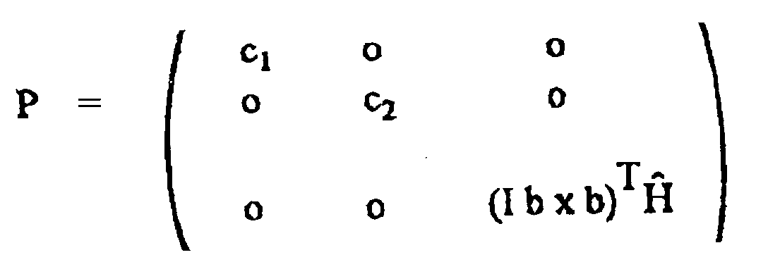
- P, N and R are square matrices, and the right-hand side of the first equation (22) represents a square shape, for which the condition (20) is known to be fulfilled if the matrix P is positive definite or positive semi-definite.
- all diagonal elements of P must be larger (positive definite) or zero (positive semidefinite).
- the M ⁇ i can be chosen to be positive or negative, the result is that the following inequality has to be satisfied: (Ib ⁇ b) T ⁇ ( H + ⁇ H ) ⁇ 0
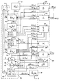
- a magnetometer 1, a computing device 10 and memory arrangements are shown 2 and 20 and a three-axis nozzle arrangement 3.
- B ⁇ (t k ) is determined in the arithmetic unit 11, the parameters T and ⁇ t being taken from the memory 2, the values relating to the preceding point in time t k-1 being taken from the memory 22 and the current value B (t k ) is obtained from magnetometer 1.
- the auxiliary variables C (t k ) are each fed to a memory 21 or values C (t k-1 ) already stored there are taken from the latter.
- the derivative B ⁇ (t k ) is fed to a further arithmetic unit 12, where the rotational speed vector ⁇ m is determined according to the formula (4), with the aid of the current value of B (t k ).
- the vector b (t k ), the matrix A (t k ) and the vector Y (t k ) are then determined in a computing unit 13 in accordance with the regulations (5), (6), (10) and (15) and these Sizes entered in a memory 23.
- the matrix A (t k ) is fed to a following arithmetic unit 14, where after calculating the matrix R (t k ) according to (25) by means of the inertia matrix I and the estimate H H (t k-1 ) taken from a memory 25 by multiplication according to (24) the matrix N (t k ) is determined.
- the activation matrix K (t k ) is then to be determined such that the matrix P (t k ) formed from K, K T and N according to (23) is positively definite or positively semidefinite. This can be done, for example, according to regulation (28), from which expression (29) results for P.
- the current value for the matrix K (t k ) is entered into a memory 24.
- H (t k ) H (t k-1 ) + ⁇ H (t k-1 ) + ⁇ t [ H (t k-1 ) x I -1 H (t k-1 ) + I -1 A T (t k-1 ) K (t k-1 ) (Y (t k-1 ) - A (t k-1 ) I -1 H (t k-1 ))]
- the parameters for ⁇ t and I are taken from the memory 2, and the matrices or vectors relating to the previous time t k-1 are taken from the memories 23, 24, 25 and 29.
- component P 33 of matrix P is now determined in accordance with regulation (29), using the current value of b (t k ) as well as the predetermined parameter size I.
- the scalar size P 33 is determined in a comparator 17 then checked whether P 33 ⁇ o applies, as required by regulation (27). If the answer is affirmative, zero is supplied to the memory 29 as the current value of ⁇ H ⁇ (t k ). Otherwise, the decisive variables for triggering pulsed torques M ⁇ i ⁇ t i ; or a corresponding change in angular momentum ⁇ H ⁇ according to (31), whereby (32) must be observed.
- the angular momentum change ⁇ H ⁇ (t k ) to be formed in accordance with (31) is then to be entered in the memory 29, and the values determined for the time intervals ⁇ t i (t k ) are fed to the nozzle arrangement 3 for triggering the corresponding torque pulses M ⁇ i ⁇ t i .
- the described computing cycle is carried out at the beginning of each new sampling interval ⁇ t k in a very short time in relation to its duration. For example, this is approximately 2 msec compared to approximately 250 msec for a sampling interval.
- the computing method converges the faster, ie the total number of integration steps required in the arithmetic unit 15 is lower, the more the requirements (32) and (27) are met.
- this depends on the degree of "over-fulfillment" of requirement (37), which, however, means an increase in energy consumption, for example. of jet fuel.
Landscapes
- Engineering & Computer Science (AREA)
- Remote Sensing (AREA)
- Combustion & Propulsion (AREA)
- Radar, Positioning & Navigation (AREA)
- Aviation & Aerospace Engineering (AREA)
- Chemical & Material Sciences (AREA)
- Automation & Control Theory (AREA)
- Life Sciences & Earth Sciences (AREA)
- General Life Sciences & Earth Sciences (AREA)
- Geochemistry & Mineralogy (AREA)
- Geology (AREA)
- Environmental & Geological Engineering (AREA)
- Measuring Magnetic Variables (AREA)
- Control Of Position, Course, Altitude, Or Attitude Of Moving Bodies (AREA)
Claims (4)
- Procédé de détermination du vecteur d'impulsion angulaire H d'un satellite situé dans un champ magnétique extérieur B par rapport à un système de coordonnées, fixes par rapport au satellite et orthogonales, dont les axes x, y, z coïncident avec les axes principaux d'inertie du satellite, le satellite disposant d'un système de génération de couples de rotation pour produire des couples de rotation pulsés autour des trois axes, caractérisé par le faitqu'il est utilisé un magnétomètre de mesure à trois axes,que les valeurs de mesure du magnétomètre (vecteur de champ magnétiqueest intégrée à des points temporels successifs en utilisant les valeurs de mesure effectives concernées, une nouvelle valeur de H étant respectivement déterminée, alors que les symboles choisis ont la signification suivante : H et M, les grandeurs estimées pour le vecteur d'impulsion de rotation ou le couple de rotation; I la matrice d'inertie du satellite et I-1 leur matrice inverse; A, une matrice carrée de rang 3 avec trois vecteurs linéaires orthogonaux entre eux, dont l'un coïncide avec l'un des vecteurs de champ magnétique normalisé
 et Ix,y,z représentant les composantes diagonales de la matrice d'inertie I,
 en vérifiant à l'aide des valeurs H ∧ déterminées respectivement par intégration et des valeurs de mesure effectives du vecteur de champ magnétique normalisé b de façon continue, si l'inégalitéqu'un couple de rotationque, enfin, la valeur déterminée pour H ∧ est identique avec le vecteur d'impulsion angulaire H à déterminer, dès que les intégrations répétées n'ont plus de modification de [H ∧] pour conséquence.
 - Procédé conformément à la revendication 1, caractérisé par le fait que entre les éléments de la matriceavec c1,2 > 0,de sorte que s'applique

- Procédé conformément à la revendication 1 ou 2, caractérisé par le fait que les intervalles de temps Δti d'après l'exigence
- Procédé conformément à l'une des revendications précédentes caractérisé par le fait que les deux vecteurs de lignes de la matrice A ne correspondant pas au vecteur de champ magnétique normalisé b dans l'hypothèse où |bz| = 1 pour

Applications Claiming Priority (2)
| Application Number | Priority Date | Filing Date | Title |
|---|---|---|---|
| DE4432265A DE4432265C2 (de) | 1994-09-10 | 1994-09-10 | Verfahren zur Bestimmung des Drehimpulsvektors eines Satelliten |
| DE4432265 | 1994-09-10 |
Publications (2)
| Publication Number | Publication Date |
|---|---|
| EP0700829A1 EP0700829A1 (fr) | 1996-03-13 |
| EP0700829B1 true EP0700829B1 (fr) | 1999-06-09 |
Family
ID=6527896
Family Applications (1)
| Application Number | Title | Priority Date | Filing Date |
|---|---|---|---|
| EP95113965A Expired - Lifetime EP0700829B1 (fr) | 1994-09-10 | 1995-09-06 | Procédé pour la détermination du vecteur d'impulsion angulaire d'un satellite |
Country Status (3)
| Country | Link |
|---|---|
| US (1) | US5702067A (fr) |
| EP (1) | EP0700829B1 (fr) |
| DE (2) | DE4432265C2 (fr) |
Families Citing this family (7)
| Publication number | Priority date | Publication date | Assignee | Title |
|---|---|---|---|---|
| US6113034A (en) * | 1997-08-04 | 2000-09-05 | Motorola, Inc. | Method and apparatus for estimating effects of disturbance forces |
| US6282467B1 (en) * | 1997-10-14 | 2001-08-28 | The Boeing Company | Three-axis inertial attitude determination for spinning spacecraft |
| DE19924908B4 (de) * | 1999-05-31 | 2008-05-29 | Astrium Gmbh | Verfahren zur dreiachsigen Lagebestimmung für einen niedrig fliegenden Satelliten |
| US11644834B2 (en) * | 2017-11-10 | 2023-05-09 | Nvidia Corporation | Systems and methods for safe and reliable autonomous vehicles |
| CN114722583B (zh) * | 2022-03-21 | 2025-04-15 | 中国西安卫星测控中心 | 基于角动量守恒的卫星瞬时受力异常分析方法 |
| CN115593657B (zh) * | 2022-10-11 | 2024-07-23 | 深圳航天东方红卫星有限公司 | 一种卫星剩磁在轨标定方法 |
| CN116331524B (zh) * | 2023-05-30 | 2023-07-21 | 北京钧天航宇技术有限公司 | 一种卫星磁力矩器安装位置的确定方法及装置 |
Family Cites Families (7)
| Publication number | Priority date | Publication date | Assignee | Title |
|---|---|---|---|---|
| US3228628A (en) * | 1963-04-30 | 1966-01-11 | Talbot A Chubb | Method and apparatus for magnetically orienting a space vehicle |
| US3232561A (en) * | 1963-06-06 | 1966-02-01 | Honeywell Inc | Control apparatus for space craft |
| US3429524A (en) * | 1965-07-19 | 1969-02-25 | Westinghouse Electric Corp | Attitude control system |
| JPS491439B1 (fr) * | 1968-09-27 | 1974-01-14 | ||
| US5123617A (en) * | 1990-03-05 | 1992-06-23 | General Electric Company | Spacecraft momentum unloading using controlled magnetic torques |
| US5047945A (en) * | 1990-08-09 | 1991-09-10 | General Electric Company | Residual magnetic dipole cancellation system for satellites |
| CA2080612A1 (fr) * | 1991-11-27 | 1993-05-28 | Douglas J. Bender | Methode et dispositif pour compenser les couples de perturbation magnetique dans un satellite |
-
1994
- 1994-09-10 DE DE4432265A patent/DE4432265C2/de not_active Expired - Fee Related
-
1995
- 1995-09-06 DE DE59506148T patent/DE59506148D1/de not_active Expired - Fee Related
- 1995-09-06 EP EP95113965A patent/EP0700829B1/fr not_active Expired - Lifetime
- 1995-09-11 US US08/526,566 patent/US5702067A/en not_active Expired - Fee Related
Also Published As
| Publication number | Publication date |
|---|---|
| DE59506148D1 (de) | 1999-07-15 |
| DE4432265C2 (de) | 1996-12-12 |
| DE4432265A1 (de) | 1996-03-14 |
| EP0700829A1 (fr) | 1996-03-13 |
| US5702067A (en) | 1997-12-30 |
Similar Documents
| Publication | Publication Date | Title |
|---|---|---|
| DE4129627C2 (de) | Vorrichtung und Verfahren zur Lageregelung eines um eine körperfeste Achse in Rotation zu versetzenden Raumfahrzeuges | |
| DE3606636C1 (de) | Verfahren zur Bestimmung von Erdmagnetfeldkomponenten bezueglich eines satellitenfesten Koordinatensystems | |
| EP1019274B1 (fr) | Procede pour appliquer des forces d'actionnement definies | |
| DE19950247A1 (de) | Regelungsanordnung und Regelungsverfahren für Sstelliten | |
| WO1993004922A1 (fr) | Satellite oriente vers la terre et stabilise sur trois axes et procede connexe d'acquisition du soleil et de la terre | |
| EP0700829B1 (fr) | Procédé pour la détermination du vecteur d'impulsion angulaire d'un satellite | |
| DE3201997C2 (de) | Verfahren zum Herabsetzen der Nutation eines Raumflugkörpers und System zum Durchführen des Verfahrens | |
| DE19601825A1 (de) | Lenksystem für ein Kraftfahrzeug | |
| EP0748737A1 (fr) | Satellite géostationnaire stabilisé en trois axes et des manoeuvres correspondants d'acquisition du soleil et de la terre | |
| EP1514799B1 (fr) | Procédé de détermination d'attitude d'un véhicule spatial en utilisant un vecteur directionel et la mesure de l'inertie totale | |
| EP3259039B1 (fr) | Procédé et dispositif pour la commande d'un simulateur | |
| DE2922415C2 (de) | Navigationsgerät für Landfahrzeuge | |
| DE602006000587T2 (de) | Verfahren und System zum Bestimmen eines Impulspfades ohne Singularität | |
| EP1118519A2 (fr) | Procédé de détection des défauts de montage d'un détecteur sur un véhicule | |
| DE3143626C2 (de) | Verfahren zum Aufnehmen von Kernresonanzspektren in einem dreidimensionalen Frequenzbereich und Kernresonanzspektrometer zur Durchführung des Verfahrens | |
| DE69000363T2 (de) | Verfahren zur mittleren windgeschwindigkeitsbestimmung relativ zum boden waehrend des fluges eines luftfahrzeugs. | |
| DE69106983T2 (de) | Verfahren der Steuerung eines Raumfahrzeuges, welche eine Präzessionsbewegung ausführt und Vorrichtung um diese zu betätigen. | |
| EP0733546B1 (fr) | Véhicule spatial stabilisé à trois axes et procédé d'acquisition du soleil | |
| EP1081018B1 (fr) | Méthode et dispositif pour la reproduction d'un couplage mécanique | |
| DE69608381T2 (de) | Verfahren und Vorrichtung zur Führung eines mobilen Objektes | |
| DE2334235A1 (de) | Verfahren und vorrichtung zur feststellung des blockierens von raedern eines fahrzeuges | |
| EP0750239B1 (fr) | Dispositif pour le réglage d'attitude et éventuellement de position d'un engin spatial et méthode correspondante | |
| DE2139053A1 (de) | Numerische Werkzeugmaschinensteue rung | |
| DE102022119973A1 (de) | Verfahren zum Betreiben eines Kraftwagens, insbesondere eines Personenkraftwagens, sowie Kraftwagen | |
| DE1481508B1 (de) | Verfahren zur Regelung der Querbeschleunigung und Rolldaempfung von lenkbaren Flugkoerpern und Einrichtung zur Durchfuehrung des Verfahrens |
Legal Events
| Date | Code | Title | Description |
|---|---|---|---|
| PUAI | Public reference made under article 153(3) epc to a published international application that has entered the european phase |
Free format text: ORIGINAL CODE: 0009012 |
|
| AK | Designated contracting states |
Kind code of ref document: A1 Designated state(s): DE FR GB IT |
|
| 17P | Request for examination filed |
Effective date: 19960823 |
|
| 17Q | First examination report despatched |
Effective date: 19980403 |
|
| GRAG | Despatch of communication of intention to grant |
Free format text: ORIGINAL CODE: EPIDOS AGRA |
|
| GRAG | Despatch of communication of intention to grant |
Free format text: ORIGINAL CODE: EPIDOS AGRA |
|
| GRAH | Despatch of communication of intention to grant a patent |
Free format text: ORIGINAL CODE: EPIDOS IGRA |
|
| GRAH | Despatch of communication of intention to grant a patent |
Free format text: ORIGINAL CODE: EPIDOS IGRA |
|
| GRAA | (expected) grant |
Free format text: ORIGINAL CODE: 0009210 |
|
| AK | Designated contracting states |
Kind code of ref document: B1 Designated state(s): DE FR GB IT |
|
| REF | Corresponds to: |
Ref document number: 59506148 Country of ref document: DE Date of ref document: 19990715 |
|
| ITF | It: translation for a ep patent filed | ||
| GBT | Gb: translation of ep patent filed (gb section 77(6)(a)/1977) |
Effective date: 19990720 |
|
| ET | Fr: translation filed | ||
| PLBE | No opposition filed within time limit |
Free format text: ORIGINAL CODE: 0009261 |
|
| STAA | Information on the status of an ep patent application or granted ep patent |
Free format text: STATUS: NO OPPOSITION FILED WITHIN TIME LIMIT |
|
| 26N | No opposition filed | ||
| REG | Reference to a national code |
Ref country code: GB Ref legal event code: IF02 |
|
| PGFP | Annual fee paid to national office [announced via postgrant information from national office to epo] |
Ref country code: GB Payment date: 20030827 Year of fee payment: 9 |
|
| PGFP | Annual fee paid to national office [announced via postgrant information from national office to epo] |
Ref country code: DE Payment date: 20030903 Year of fee payment: 9 |
|
| PGFP | Annual fee paid to national office [announced via postgrant information from national office to epo] |
Ref country code: FR Payment date: 20030904 Year of fee payment: 9 |
|
| PG25 | Lapsed in a contracting state [announced via postgrant information from national office to epo] |
Ref country code: GB Free format text: LAPSE BECAUSE OF NON-PAYMENT OF DUE FEES Effective date: 20040906 |
|
| PG25 | Lapsed in a contracting state [announced via postgrant information from national office to epo] |
Ref country code: DE Free format text: LAPSE BECAUSE OF NON-PAYMENT OF DUE FEES Effective date: 20050401 |
|
| GBPC | Gb: european patent ceased through non-payment of renewal fee |
Effective date: 20040906 |
|
| PG25 | Lapsed in a contracting state [announced via postgrant information from national office to epo] |
Ref country code: FR Free format text: LAPSE BECAUSE OF NON-PAYMENT OF DUE FEES Effective date: 20050531 |
|
| REG | Reference to a national code |
Ref country code: FR Ref legal event code: ST |
|
| PG25 | Lapsed in a contracting state [announced via postgrant information from national office to epo] |
Ref country code: IT Free format text: LAPSE BECAUSE OF NON-PAYMENT OF DUE FEES;WARNING: LAPSES OF ITALIAN PATENTS WITH EFFECTIVE DATE BEFORE 2007 MAY HAVE OCCURRED AT ANY TIME BEFORE 2007. THE CORRECT EFFECTIVE DATE MAY BE DIFFERENT FROM THE ONE RECORDED. Effective date: 20050906 |