EP0700490B1 - Motion damper for large structures - Google Patents
Motion damper for large structures Download PDFInfo
- Publication number
- EP0700490B1 EP0700490B1 EP94917212A EP94917212A EP0700490B1 EP 0700490 B1 EP0700490 B1 EP 0700490B1 EP 94917212 A EP94917212 A EP 94917212A EP 94917212 A EP94917212 A EP 94917212A EP 0700490 B1 EP0700490 B1 EP 0700490B1
- Authority
- EP
- European Patent Office
- Prior art keywords
- energy absorbing
- absorbing material
- shaft
- outer jacket
- damper
- Prior art date
- Legal status (The legal status is an assumption and is not a legal conclusion. Google has not performed a legal analysis and makes no representation as to the accuracy of the status listed.)
- Expired - Lifetime
Links
- 230000033001 locomotion Effects 0.000 title claims description 25
- 239000011358 absorbing material Substances 0.000 claims description 27
- 230000002706 hydrostatic effect Effects 0.000 claims description 16
- 239000004809 Teflon Substances 0.000 claims description 3
- 229920006362 Teflon® Polymers 0.000 claims description 3
- NRTOMJZYCJJWKI-UHFFFAOYSA-N Titanium nitride Chemical compound [Ti]#N NRTOMJZYCJJWKI-UHFFFAOYSA-N 0.000 claims description 3
- 239000011521 glass Substances 0.000 claims description 3
- 229910010293 ceramic material Inorganic materials 0.000 claims description 2
- 239000000463 material Substances 0.000 description 14
- 238000006073 displacement reaction Methods 0.000 description 9
- 229910000831 Steel Inorganic materials 0.000 description 8
- 239000010959 steel Substances 0.000 description 8
- 238000012360 testing method Methods 0.000 description 8
- 238000001125 extrusion Methods 0.000 description 6
- 238000002955 isolation Methods 0.000 description 6
- 239000006096 absorbing agent Substances 0.000 description 5
- 230000000694 effects Effects 0.000 description 5
- 239000004033 plastic Substances 0.000 description 5
- 238000013016 damping Methods 0.000 description 4
- 239000013536 elastomeric material Substances 0.000 description 4
- 238000010276 construction Methods 0.000 description 3
- 238000001953 recrystallisation Methods 0.000 description 3
- 125000006850 spacer group Chemical group 0.000 description 3
- XEEYBQQBJWHFJM-UHFFFAOYSA-N Iron Chemical compound [Fe] XEEYBQQBJWHFJM-UHFFFAOYSA-N 0.000 description 2
- VYPSYNLAJGMNEJ-UHFFFAOYSA-N Silicium dioxide Chemical compound O=[Si]=O VYPSYNLAJGMNEJ-UHFFFAOYSA-N 0.000 description 2
- 238000005266 casting Methods 0.000 description 2
- 238000006243 chemical reaction Methods 0.000 description 2
- 230000006835 compression Effects 0.000 description 2
- 238000007906 compression Methods 0.000 description 2
- 230000001351 cycling effect Effects 0.000 description 2
- 239000008187 granular material Substances 0.000 description 2
- 239000004519 grease Substances 0.000 description 2
- 239000000314 lubricant Substances 0.000 description 2
- 238000011084 recovery Methods 0.000 description 2
- 230000002269 spontaneous effect Effects 0.000 description 2
- 238000005482 strain hardening Methods 0.000 description 2
- 238000005406 washing Methods 0.000 description 2
- 229910001369 Brass Inorganic materials 0.000 description 1
- 229910000978 Pb alloy Inorganic materials 0.000 description 1
- ATJFFYVFTNAWJD-UHFFFAOYSA-N Tin Chemical compound [Sn] ATJFFYVFTNAWJD-UHFFFAOYSA-N 0.000 description 1
- HCHKCACWOHOZIP-UHFFFAOYSA-N Zinc Chemical compound [Zn] HCHKCACWOHOZIP-UHFFFAOYSA-N 0.000 description 1
- 229910045601 alloy Inorganic materials 0.000 description 1
- 239000000956 alloy Substances 0.000 description 1
- 230000004075 alteration Effects 0.000 description 1
- 239000004411 aluminium Substances 0.000 description 1
- 229910052782 aluminium Inorganic materials 0.000 description 1
- XAGFODPZIPBFFR-UHFFFAOYSA-N aluminium Chemical compound [Al] XAGFODPZIPBFFR-UHFFFAOYSA-N 0.000 description 1
- PNEYBMLMFCGWSK-UHFFFAOYSA-N aluminium oxide Inorganic materials [O-2].[O-2].[O-2].[Al+3].[Al+3] PNEYBMLMFCGWSK-UHFFFAOYSA-N 0.000 description 1
- 239000011324 bead Substances 0.000 description 1
- 239000010951 brass Substances 0.000 description 1
- 230000008878 coupling Effects 0.000 description 1
- 238000010168 coupling process Methods 0.000 description 1
- 238000005859 coupling reaction Methods 0.000 description 1
- 125000004122 cyclic group Chemical group 0.000 description 1
- 238000007667 floating Methods 0.000 description 1
- 229910052742 iron Inorganic materials 0.000 description 1
- 230000007246 mechanism Effects 0.000 description 1
- 229910052751 metal Inorganic materials 0.000 description 1
- 239000002184 metal Substances 0.000 description 1
- 150000002739 metals Chemical class 0.000 description 1
- 238000000034 method Methods 0.000 description 1
- 238000012986 modification Methods 0.000 description 1
- 230000004048 modification Effects 0.000 description 1
- 229910052573 porcelain Inorganic materials 0.000 description 1
- 230000008569 process Effects 0.000 description 1
- 239000012858 resilient material Substances 0.000 description 1
- HBMJWWWQQXIZIP-UHFFFAOYSA-N silicon carbide Chemical compound [Si+]#[C-] HBMJWWWQQXIZIP-UHFFFAOYSA-N 0.000 description 1
- 229910010271 silicon carbide Inorganic materials 0.000 description 1
- 239000000377 silicon dioxide Substances 0.000 description 1
- 229910052718 tin Inorganic materials 0.000 description 1
- 239000011135 tin Substances 0.000 description 1
- 239000011701 zinc Substances 0.000 description 1
- 229910052725 zinc Inorganic materials 0.000 description 1
Images


Classifications
-
- F—MECHANICAL ENGINEERING; LIGHTING; HEATING; WEAPONS; BLASTING
- F16—ENGINEERING ELEMENTS AND UNITS; GENERAL MEASURES FOR PRODUCING AND MAINTAINING EFFECTIVE FUNCTIONING OF MACHINES OR INSTALLATIONS; THERMAL INSULATION IN GENERAL
- F16F—SPRINGS; SHOCK-ABSORBERS; MEANS FOR DAMPING VIBRATION
- F16F7/00—Vibration-dampers; Shock-absorbers
- F16F7/12—Vibration-dampers; Shock-absorbers using plastic deformation of members
- F16F7/127—Vibration-dampers; Shock-absorbers using plastic deformation of members by a blade element cutting or tearing into a quantity of material; Pultrusion of a filling material
Definitions
- This invention relates to dampers of the type commonly referred to as extrusion dampers, used for reducing the effects of induced motion or displacement in a variety of structures and equipment.
- the dampers of the invention may be used in large structures such as bridges or buildings to reduce the effects of motion induced during earthquakes or from strong winds. They may also be used to damp motion of large or small moving objects. They may be used to damp motion in industrial machinery or engines or the like or from domestic appliances such as washing machines for example, or in any other application where it is desired to damp any motion, vibrations or similar. They may be used to damp displacement arising from thermal expansion.
- the extrusion dampers of the invention have various applications.
- Lead is the preferred deformable energy absorbing material for several reasons. First it yields at a room temperature shear stress of around 10.5MPa which is low compared with other metals and equivalent plastic materials. Second it restores its mechanical properties through recrystallisation and associated processes relatively rapidly following yield deformations, which provides outstanding resistance to work hardening under cyclic shear at ordinary temperatures. Third lead is readily available at the purity required to exhibit these properties.
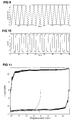
- dampers are individually designed to protect a particular structure against damage by damping certain motions imparted to it. Their behaviour is quite closely approximated by that of an ideal Coulomb damper in having a force-displacement hysteresis loop which is nearly rectangular and practically rate independent over a wide range of frequencies. Research into performance of these devices is ongoing.
- the invention broadly comprises a damper for interposing between two members to damp motion which may be induced between the two, comprising an elongate outer jacket means, a shaft passing through the outer jacket which is forced to move through the outer jacket during induced motion and a body of a plastically deformable energy absorbing material filling the space between the outer jacket and the shaft, wherein the body of energy absorbing material is fixed relative to the outer jacket and the shaft comprises a portion of reduced diameter which is forced through the energy absorbing material during said induced motion or the body of energy absorbing material is fixed to the shaft and the outer jacket comprises a portion of enlarged diameter through which the body of energy absorbing material is forced during said induced motion.
- the body of energy absorbing material is subjected to approximately hydrostatic pressure at least approaching the shear yield stress of the material.
- the hydrostatic pressure applied to the energy absorbing material exceeds the shear yield stress of the energy absorbing material.
- the hydrostatic pressure is 5MPa or more and most preferably in the range 10-100MPa.
- the energy absorbing material is lead, but other energy absorbing materials which may be used include alloys of lead, aluminium at elevated temperature e.g. about 200°C, tin, zinc, brass, iron, super plastic alloys, or any other material having a low rate of work hardening, including also densely packed granular materials such as steel shot, glass beads, alumina, silica, silicon carbide or any other very hard granular material.
- Dampers of the invention may be used in seismic isolation applications to damp seismic motion in large structures such as bridges or buildings or motion from very strong wind buffeting or similar. They may also be used in any other application where it is desired to damp any motion, vibrations, or similar.
- dampers of the invention may be used to damp motion of engines or other industrial machinery. In domestic applications, dampers of the invention may be used in washing machines or spin dryers or dish washers to isolate vibrations. Small size dampers of the invention may be used as "microisolators" for sensitive electronic equipment such as the mechanism of a video recorder etc or in other similar applications. Numerous applications of the extrusion dampers of the invention are envisaged and the invention is not limited only to seismic isolation dampers.
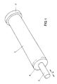
- the dampers shown in Figs 1 to 5 each comprise an outer jacket 1 which is typically formed of steel and may be cylindrical as shown, but could be of other cross-sectional shapes such as oval for example.
- a shaft 2 is able to move longitudinally through the outer jacket 1 in the direction of arrow A in each case. It is not necessary for the shaft to be positioned centrally within the outer jacket 1, but it could instead be off-set somewhat.
- the shaft is also typically formed of steel.
- the space between the outer jacket 1 and shaft 2 is filled with a plastically deformable material such as lead so that in use the shaft moves through the lead.
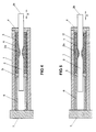
- the shaft 2 moves through end cap 4 which also forms a bearing for one end of the shaft and bearing 5 on the other side which floats.
- a tubular spacer 6 is provided between an end cap 7 and the floating bearing 5.
- a central part 2a of the shaft 2 has a reduced diameter as shown.
- Fig. 1 shows the damper from the exterior while Figs 2 to 5 show the damper in longitudinal cross-section showing variations in construction which will be referred to further later.
- the outer jacket 1 of the damper is coupled to one member of a building or other structure through a suitable mechanical coupling, and the shaft is coupled to another member, through the end 2b of the shaft, which may move relative to the first in an induced motion.
- the shaft 2 and in particular the reduced diameter part 2a is forced through the deformable material 3 such as lead, which creates a damping effect by conversion of kinetic energy to plastic deformational energy and heat, and further heat during re-crystallisation and other spontaneous recovery processes.
- the energy absorbing material may optionally be prestressed under an approximately hydrostatic pressure at least approaching and preferably exceeding the shear yield stress of the material so that the material will always be in compression. With lead pressures of 5MPa or more, typically 10MPa to around 30MPa, but also up to 100MPa or more have been found effective.
- a hydrostatic pressure applied to a body is then defined as one third the sum of the three principal stresses which act upon it.
- the hydrostatic pressure is 0, and the principal tensile stress ⁇ x , the principal compressive stress ⁇ y and the maximum shear stress ⁇ ' xy are all equal in magnitude.
- a hydrostatic pressure p equal to the shear stress ⁇ ' xy has been applied. The maximum tensile stress is then 0 so that the body is always under compression. Therefore the body cannot fail in tension.
- a block comprising layers of an elastomeric material 8 such as rubber and rigid material 9 such as steel is provided between the tubular spacer 6 and the end cap 7.
- a pad 10 of elastomeric material such as rubber is provided at either end of the absorber material 3.
- the length of the spacer 5 is such that when the end cap 4 is screwed home, the desired hydrostatic pressure is applied to the lead 3.
- the exterior of the body of absorber material 3 is surrounded by a sleeve of elastomeric material such as rubber or reinforced rubber or other resilient material.
- the absorber material is entirely encased in such a layer of elastomeric material 12.
- the energy absorbing material 3 may be cast directly into place within the outer jacket 1 and around the shaft 2.
- the rubber sleeve or casing may be stretched around the lead body after casting around the shaft and the shaft and lead then press fitted into the outer casing.
- the lead may be cast as a plug with a constant diameter bore through the lead. The lead plug may then be inserted into the outer casing and the shaft then pressed into the central bore through the lead. Pressure may then be applied to the lead, for example by fitting of the end cap 4 or equivalent, to compress the lead to cause the lead to move to surround the reduced diameter part 2a of the shaft completely.
- damper may be cylindrical or alternatively oval, square, rectangular or any other desired shape in overall cross-sectional shape.
- the shaft and also other parts of the damper may optionally be coated with teflon, porcelain, titanium nitride, a hard ceramic material, glass, or similar.
- the component parts are coated with a high temperature/pressure grease or other lubricant.
- Fig. 6 shows another type of damper of the invention.
- the damper comprises an outer jacket 21 typically formed of steel which is desirably cylindrical but could be of other cross-sectional shapes.
- One part of the outer jacket 21 is formed with a portion 21a of enlarged diameter as shown.
- a shaft 22 which is enlarged at either end 22a passes through the outer jacket 21.
- the ends 22a of the shaft form plungers within the outer jacket 21.
- Seals 26 such as chevron seals may be provided to seal the plunger parts 22a of the shaft against the internal bore of the outer jacket. Parts of the plunger ends 22a of the shaft 22 are shown in cross-section.
- the end of the shaft extends out of the outer jacket further than shown in the drawings on at least one side, to enable the shaft to be coupled into position in use.
- the shaft has a reduced diameter centre part 22b.
- the shaft is shown as a three part shaft with the reduced diameter centre part 22b threading into the larger diameter parts 22a of the shaft at either end, as indicated at 22c.
- a body of lead 23 or other energy absorbing material is fixed around the reduced diameter part 22b of the shaft 22.
- the lead may be subjected to hydrostatic pressure by screwing the plunger ends 22a onto the centre shaft part 22b to apply the desired pressure to the lead, which is also confined within the outer jacket 1.
- Other arrangements are possible.
- the outer jacket 21 is coupled to one member of a building or other structure, and one or both ends of the shaft 22 are attached to another member which may move relative to the first in an induced motion.
- the shaft 22 moves relative to the outer jacket 21, as it does so forcing the body of lead 23 through the interior of the outer jacket 21 including the enlarged diameter portion 21a in the outer jacket, creating a damping effect by conversion of kinetic energy to plastic deformational energy, and to further heat during re-crystallisation and other spontaneous recovery processes.
- shaft and also the interior of the outer jacket may be coated with teflon, porcelane, titanium nitride etc and the component parts of the damper may be coated with a high temperature grease during assembly, as referred to previously.
- a damper was constructed comprising a cylindrical outer jacket of steel of internal diameter 40mm.
- the shaft was a cylindrical steel shaft of 19mm diameter with a central portion 20mm long in which the diameter of the shaft reduced smoothly to 12mm minimum diameter and then increased back to the normal diameter of the shaft.
- Lead of 99.9% purity was cast into place between the outer jacket and the centrally positioned shaft to surround the shaft within the outer jacket.
- the length of the lead slug fixed within the casing and surrounding the shaft was 130mm. Before casting the lead into place the shaft was coated with a high pressure lubricant. When the end cap of the outer jacket was screwed home the lead was subjected to approximately 20MPa hydrostatic pressure.
Landscapes
- Engineering & Computer Science (AREA)
- General Engineering & Computer Science (AREA)
- Mechanical Engineering (AREA)
- Buildings Adapted To Withstand Abnormal External Influences (AREA)
- Vibration Prevention Devices (AREA)
- Vibration Dampers (AREA)
- Fluid-Damping Devices (AREA)
Applications Claiming Priority (3)
| Application Number | Priority Date | Filing Date | Title |
|---|---|---|---|
| NZ24777193 | 1993-06-02 | ||
| NZ24777193 | 1993-06-02 | ||
| PCT/NZ1994/000054 WO1994028334A1 (en) | 1993-06-02 | 1994-06-02 | Motion damper for large structures |
Publications (3)
| Publication Number | Publication Date |
|---|---|
| EP0700490A1 EP0700490A1 (en) | 1996-03-13 |
| EP0700490A4 EP0700490A4 (en) | 1996-05-15 |
| EP0700490B1 true EP0700490B1 (en) | 1998-04-15 |
Family
ID=19924364
Family Applications (3)
| Application Number | Title | Priority Date | Filing Date |
|---|---|---|---|
| EP94917212A Expired - Lifetime EP0700490B1 (en) | 1993-06-02 | 1994-06-02 | Motion damper for large structures |
| EP94917210A Withdrawn EP0700488A4 (en) | 1993-06-02 | 1994-06-02 | MOTION DAMPER FOR EXTENSIVE STRUCTURES |
| EP94917211A Withdrawn EP0700489A4 (en) | 1993-06-02 | 1994-06-02 | MOTION DAMPER FOR EXTENSIVE STRUCTURES |
Family Applications After (2)
| Application Number | Title | Priority Date | Filing Date |
|---|---|---|---|
| EP94917210A Withdrawn EP0700488A4 (en) | 1993-06-02 | 1994-06-02 | MOTION DAMPER FOR EXTENSIVE STRUCTURES |
| EP94917211A Withdrawn EP0700489A4 (en) | 1993-06-02 | 1994-06-02 | MOTION DAMPER FOR EXTENSIVE STRUCTURES |
Country Status (8)
| Country | Link |
|---|---|
| US (1) | US6220410B1 (show.php) |
| EP (3) | EP0700490B1 (show.php) |
| JP (3) | JPH08510540A (show.php) |
| KR (2) | KR960702893A (show.php) |
| CN (3) | CN1124993A (show.php) |
| AU (3) | AU6859994A (show.php) |
| TW (3) | TW255948B (show.php) |
| WO (3) | WO1994028333A1 (show.php) |
Families Citing this family (29)
| Publication number | Priority date | Publication date | Assignee | Title |
|---|---|---|---|---|
| DE19636475B4 (de) * | 1996-09-07 | 2004-03-04 | Itw-Ateco Gmbh | Rotationsdämpfer |
| JPH10196157A (ja) * | 1996-12-27 | 1998-07-28 | Mitsubishi Heavy Ind Ltd | エネルギ吸収装置 |
| DE29709957U1 (de) * | 1997-06-07 | 1997-10-16 | Willi Elbe Gelenkwellen Gmbh & | Lenksäule mit integriertem Crashelement |
| CN1074513C (zh) * | 1998-12-31 | 2001-11-07 | 李岭群 | 万向减震器 |
| EP1031680B1 (fr) | 1999-02-26 | 2005-08-31 | Vinci Construction Grands Projets | Dispositif parasismique élastoplastique articulé pour ouvrage de génie civil, et ouvrage d'art tel qu'un pont comportant ledit dispositif |
| FR2795793B1 (fr) * | 1999-07-01 | 2001-08-03 | Snecma | Biellette fusible a absorption d'energie |
| JP2006342853A (ja) * | 2005-06-08 | 2006-12-21 | Sumitomo Metal Mining Co Ltd | 振動エネルギー吸収装置 |
| US20110308190A1 (en) | 2006-12-22 | 2011-12-22 | Simpson Strong-Tie Co., Inc. | Moment frame connector |
| US20080148681A1 (en) * | 2006-12-22 | 2008-06-26 | Badri Hiriyur | Moment frame connector |
| US20080174095A1 (en) * | 2007-01-18 | 2008-07-24 | Ridgway Jason R | Energy absorption mechanism for collapsible assembly |
| JP5719200B2 (ja) * | 2011-03-08 | 2015-05-13 | 株式会社東京鐵骨橋梁 | シリンダ型ダンパー装置 |
| CN103015552B (zh) * | 2011-09-22 | 2014-11-05 | 同济大学 | 防震断变形记录式屈曲约束支撑及其制造方法 |
| ITMC20110066A1 (it) * | 2011-11-21 | 2012-02-20 | Giuseppe Gentili | Modulo per la dissipazione sismica costituito da sfere resistenti alla compressione immerse in un materiale a bassa densita' variabile. |
| US8844205B2 (en) * | 2012-01-06 | 2014-09-30 | The Penn State Research Foundation | Compressed elastomer damper for earthquake hazard reduction |
| CN103469921B (zh) * | 2013-09-12 | 2015-08-26 | 北京交通大学 | 预压弹簧自恢复耗能支撑 |
| CN103967113A (zh) * | 2014-04-12 | 2014-08-06 | 北京工业大学 | 工业化装配式多、高层钢结构单板自复位偏心支撑体系 |
| CN103967119A (zh) * | 2014-04-12 | 2014-08-06 | 北京工业大学 | 装配式多、高层钢结构自复位双板人字形预应力支撑体系 |
| CN103967114A (zh) * | 2014-04-12 | 2014-08-06 | 北京工业大学 | 装配式多、高层钢结构一字自复位偏心预应力支撑体系 |
| CN104153481B (zh) * | 2014-08-27 | 2017-01-25 | 广州大学 | 一种挤压阻尼器装置 |
| CN104453003B (zh) * | 2014-10-28 | 2016-06-01 | 沈阳建筑大学 | 螺旋铅挤压阻尼器 |
| SG11201704356SA (en) * | 2014-12-04 | 2017-06-29 | Eddy Current Ltd Partnership | Energy absorbing apparatus |
| JP6511411B2 (ja) * | 2016-03-23 | 2019-05-15 | 不二ラテックス株式会社 | ショックアブソーバ |
| CN105805476B (zh) * | 2016-04-27 | 2018-01-02 | 国核电力规划设计研究院 | 高能管道冲击吸能器 |
| CN106122347A (zh) * | 2016-08-09 | 2016-11-16 | 中国电力科学研究院 | 一种减震器 |
| CN106592808A (zh) * | 2017-01-22 | 2017-04-26 | 北京工业大学 | 大行程筒式铅剪切阻尼器 |
| CN107237422A (zh) * | 2017-08-17 | 2017-10-10 | 中国地震局工程力学研究所 | 一种两端销轴连接双向铅挤压耗能阻尼器 |
| US11427337B2 (en) | 2019-01-30 | 2022-08-30 | Goodrich Corporation | Radial slit disc energy attenuation system |
| CN111851788B (zh) * | 2020-08-06 | 2021-11-16 | 同济大学 | 一种可调节的波纹钢板—铅复合双功能构件 |
| CN113958001B (zh) * | 2021-12-22 | 2022-03-04 | 北京市建筑设计研究院有限公司 | 并联多重套管式双屈服点屈曲约束支撑 |
Family Cites Families (14)
| Publication number | Priority date | Publication date | Assignee | Title |
|---|---|---|---|---|
| US3053526A (en) * | 1958-12-31 | 1962-09-11 | Menasco Mfg Company | Dampers and damped springs |
| US3365189A (en) * | 1966-02-03 | 1968-01-23 | Miner Inc W H | Cushioning device |
| CA957389A (en) * | 1971-02-24 | 1974-11-05 | Massimo Casciola | Emergency shock absorber for the dissipation of kinetic energy of moving masses |
| AU463143B2 (en) * | 1971-12-22 | 1975-07-17 | New Zealand Inventions Development Authority | Improvements in or relating toa cyclic energy absorber |
| US3721320A (en) * | 1972-08-26 | 1973-03-20 | J Hirsch | Energy absorption apparatus |
| GB1386646A (en) * | 1972-10-17 | 1975-03-12 | Menasco Mfg Co | Damping apparatus |
| DE2313483A1 (de) * | 1973-03-19 | 1974-10-03 | Interatom | Schwingungsdaempfer, insbesondere zur sicherung von rohrleitungen gegen erdbeben |
| US3820634A (en) * | 1973-08-10 | 1974-06-28 | Hartwell Corp | Shock resisting energy absorbing device |
| GB2048430A (en) * | 1979-04-09 | 1980-12-10 | Imi Kynoch Ltd | Device absorbing energy by extrusion |
| JPS61266841A (ja) * | 1985-05-13 | 1986-11-26 | Toshiba Corp | 振動吸収装置 |
| JPH0280827A (ja) * | 1988-09-14 | 1990-03-20 | Daicel Chem Ind Ltd | 弾性構造体 |
| GB9120299D0 (en) * | 1991-09-24 | 1991-11-06 | Latchways Ltd | Load attachment system, and parts fittings therefor |
| NZ245378A (en) * | 1992-12-04 | 1997-04-24 | Damping Systems Ltd Substitute | Bearing with plastically deformable core and surround which hydrostatically pressures the material of the core at or beyond its shear yield stress and methods of making |
| JP3277604B2 (ja) * | 1993-04-21 | 2002-04-22 | オイレス工業株式会社 | エネルギ吸収装置 |
-
1994
- 1994-06-02 EP EP94917212A patent/EP0700490B1/en not_active Expired - Lifetime
- 1994-06-02 EP EP94917210A patent/EP0700488A4/en not_active Withdrawn
- 1994-06-02 CN CN94192333A patent/CN1124993A/zh active Pending
- 1994-06-02 EP EP94917211A patent/EP0700489A4/en not_active Withdrawn
- 1994-06-02 WO PCT/NZ1994/000053 patent/WO1994028333A1/en not_active Ceased
- 1994-06-02 CN CN94192335A patent/CN1124995A/zh active Pending
- 1994-06-02 KR KR1019950705436A patent/KR960702893A/ko not_active Withdrawn
- 1994-06-02 JP JP7500512A patent/JPH08510540A/ja active Pending
- 1994-06-02 AU AU68599/94A patent/AU6859994A/en not_active Abandoned
- 1994-06-02 AU AU69000/94A patent/AU6900094A/en not_active Abandoned
- 1994-06-02 JP JP7500511A patent/JPH08510539A/ja active Pending
- 1994-06-02 AU AU69001/94A patent/AU6900194A/en not_active Abandoned
- 1994-06-02 CN CN94192334A patent/CN1124994A/zh active Pending
- 1994-06-02 WO PCT/NZ1994/000052 patent/WO1994028332A1/en not_active Ceased
- 1994-06-02 WO PCT/NZ1994/000054 patent/WO1994028334A1/en not_active Ceased
- 1994-06-02 US US08/564,142 patent/US6220410B1/en not_active Expired - Fee Related
- 1994-06-02 JP JP7500513A patent/JPH08510820A/ja active Pending
- 1994-07-14 TW TW083106394A patent/TW255948B/zh active
- 1994-07-14 TW TW083106395A patent/TW282508B/zh active
- 1994-07-14 TW TW083106396A patent/TW275099B/zh active
-
1995
- 1995-12-02 KR KR1019950705437A patent/KR960702894A/ko not_active Withdrawn
Also Published As
| Publication number | Publication date |
|---|---|
| EP0700489A1 (en) | 1996-03-13 |
| US6220410B1 (en) | 2001-04-24 |
| EP0700488A4 (en) | 1996-05-15 |
| WO1994028334A1 (en) | 1994-12-08 |
| WO1994028333A1 (en) | 1994-12-08 |
| CN1124995A (zh) | 1996-06-19 |
| TW282508B (show.php) | 1996-08-01 |
| EP0700490A4 (en) | 1996-05-15 |
| JPH08510540A (ja) | 1996-11-05 |
| AU6859994A (en) | 1994-12-20 |
| AU6900194A (en) | 1994-12-20 |
| KR960702894A (ko) | 1996-05-23 |
| KR960702893A (ko) | 1996-05-23 |
| AU6900094A (en) | 1994-12-20 |
| CN1124994A (zh) | 1996-06-19 |
| CN1124993A (zh) | 1996-06-19 |
| EP0700489A4 (en) | 1996-05-15 |
| TW275099B (show.php) | 1996-05-01 |
| EP0700490A1 (en) | 1996-03-13 |
| EP0700488A1 (en) | 1996-03-13 |
| WO1994028332A1 (en) | 1994-12-08 |
| JPH08510820A (ja) | 1996-11-12 |
| TW255948B (show.php) | 1995-09-01 |
| JPH08510539A (ja) | 1996-11-05 |
Similar Documents
| Publication | Publication Date | Title |
|---|---|---|
| EP0700490B1 (en) | Motion damper for large structures | |
| US5655756A (en) | Energy absorbers and methods of manufacture | |
| US11242908B2 (en) | Self-centering viscous damper with pre-pressed ring springs | |
| AU620587B2 (en) | Improvements in or relating to energy absorbers | |
| JP4964231B2 (ja) | エネルギ吸収・力制限摩擦カップリング | |
| CN113685072A (zh) | 一种自复位减震支撑及消能方法 | |
| US20180274618A1 (en) | Bi-linear energy dissipating and shock absorbing device for cable subjected to tension | |
| CN107514069A (zh) | 低频形状记忆合金智能非线性调谐质量阻尼器及其制作方法 | |
| KR100810518B1 (ko) | 초탄성 형상기억합금을 이용한 댐퍼 | |
| Robinson et al. | Properties of an extrusion energy absorber | |
| CN206693717U (zh) | 一种自复位形状记忆合金阻尼器 | |
| JPS5830470B2 (ja) | 周期的エネルギ−吸収装置 | |
| KR100337738B1 (ko) | 대형구조물용운동댐퍼 | |
| NZ266895A (en) | Motion damper for large structures | |
| CN205443912U (zh) | 钢阻尼抗震装置 | |
| NZ266893A (en) | Motion damper for large structures | |
| CN209909074U (zh) | 一种金属橡胶复合减震器 | |
| CN107448044A (zh) | 一种自复位形状记忆合金阻尼器及其装配方法 | |
| JP2010255850A (ja) | ダンパー装置 | |
| CN110863490A (zh) | 一种压力型减震消能预应力锚索结构及构造方法 | |
| CN110863489A (zh) | 一种压力型减震消能预应力锚杆结构及构造方法 | |
| Dithurson et al. | Experimental Investigation of High-Force-To-Volume Extrusion Damper Subjected to Cyclic and Time History Loading | |
| JPH0723108U (ja) | ブレース装置 | |
| CN106286669A (zh) | 一种早期刚度可预设的螺旋弹簧阻尼器 | |
| Scheaua | SEISMIC PROTECTION OF STRUCTURES USING HYDRAULIC DAMPER DEVICES. |
Legal Events
| Date | Code | Title | Description |
|---|---|---|---|
| PUAI | Public reference made under article 153(3) epc to a published international application that has entered the european phase |
Free format text: ORIGINAL CODE: 0009012 |
|
| 17P | Request for examination filed |
Effective date: 19951215 |
|
| AK | Designated contracting states |
Kind code of ref document: A1 Designated state(s): IT |
|
| A4 | Supplementary search report drawn up and despatched |
Effective date: 19960327 |
|
| AK | Designated contracting states |
Kind code of ref document: A4 Designated state(s): IT |
|
| RAP1 | Party data changed (applicant data changed or rights of an application transferred) |
Owner name: DAMPING SYSTEMS LIMITED |
|
| GRAG | Despatch of communication of intention to grant |
Free format text: ORIGINAL CODE: EPIDOS AGRA |
|
| 17Q | First examination report despatched |
Effective date: 19970730 |
|
| GRAG | Despatch of communication of intention to grant |
Free format text: ORIGINAL CODE: EPIDOS AGRA |
|
| GRAG | Despatch of communication of intention to grant |
Free format text: ORIGINAL CODE: EPIDOS AGRA |
|
| GRAH | Despatch of communication of intention to grant a patent |
Free format text: ORIGINAL CODE: EPIDOS IGRA |
|
| GRAH | Despatch of communication of intention to grant a patent |
Free format text: ORIGINAL CODE: EPIDOS IGRA |
|
| GRAA | (expected) grant |
Free format text: ORIGINAL CODE: 0009210 |
|
| AK | Designated contracting states |
Kind code of ref document: B1 Designated state(s): IT |
|
| ITF | It: translation for a ep patent filed | ||
| PLBE | No opposition filed within time limit |
Free format text: ORIGINAL CODE: 0009261 |
|
| STAA | Information on the status of an ep patent application or granted ep patent |
Free format text: STATUS: NO OPPOSITION FILED WITHIN TIME LIMIT |
|
| 26N | No opposition filed | ||
| PG25 | Lapsed in a contracting state [announced via postgrant information from national office to epo] |
Ref country code: IT Free format text: LAPSE BECAUSE OF NON-PAYMENT OF DUE FEES;WARNING: LAPSES OF ITALIAN PATENTS WITH EFFECTIVE DATE BEFORE 2007 MAY HAVE OCCURRED AT ANY TIME BEFORE 2007. THE CORRECT EFFECTIVE DATE MAY BE DIFFERENT FROM THE ONE RECORDED. Effective date: 20050602 |