EP0700217A2 - Procédé et appareil pour la correction de l'équilibre du blanc d'un signal vidéo couleur - Google Patents
Procédé et appareil pour la correction de l'équilibre du blanc d'un signal vidéo couleur Download PDFInfo
- Publication number
- EP0700217A2 EP0700217A2 EP95112637A EP95112637A EP0700217A2 EP 0700217 A2 EP0700217 A2 EP 0700217A2 EP 95112637 A EP95112637 A EP 95112637A EP 95112637 A EP95112637 A EP 95112637A EP 0700217 A2 EP0700217 A2 EP 0700217A2
- Authority
- EP
- European Patent Office
- Prior art keywords
- correction
- component
- color
- color image
- image signal
- Prior art date
- Legal status (The legal status is an assumption and is not a legal conclusion. Google has not performed a legal analysis and makes no representation as to the accuracy of the status listed.)
- Granted
Links
- 238000000034 method Methods 0.000 title claims description 17
- 238000012937 correction Methods 0.000 claims abstract description 104
- 239000011159 matrix material Substances 0.000 claims abstract description 6
- 230000006870 function Effects 0.000 claims description 33
- 230000015654 memory Effects 0.000 claims description 14
- 230000010354 integration Effects 0.000 claims description 13
- 238000001514 detection method Methods 0.000 claims description 10
- 230000001419 dependent effect Effects 0.000 claims description 4
- 210000004400 mucous membrane Anatomy 0.000 abstract description 15
- 230000000694 effects Effects 0.000 abstract description 3
- 230000005540 biological transmission Effects 0.000 abstract 1
- 230000003287 optical effect Effects 0.000 abstract 1
- 210000000056 organ Anatomy 0.000 description 14
- 230000006399 behavior Effects 0.000 description 4
- 238000005286 illumination Methods 0.000 description 4
- 230000008859 change Effects 0.000 description 3
- 230000004069 differentiation Effects 0.000 description 3
- 230000003595 spectral effect Effects 0.000 description 3
- 238000010586 diagram Methods 0.000 description 2
- 230000031700 light absorption Effects 0.000 description 2
- 239000000203 mixture Substances 0.000 description 2
- 230000033764 rhythmic process Effects 0.000 description 2
- 230000035945 sensitivity Effects 0.000 description 2
- 230000003068 static effect Effects 0.000 description 2
- 238000011477 surgical intervention Methods 0.000 description 2
- 238000010521 absorption reaction Methods 0.000 description 1
- 230000003321 amplification Effects 0.000 description 1
- 230000017531 blood circulation Effects 0.000 description 1
- 238000006243 chemical reaction Methods 0.000 description 1
- 239000011248 coating agent Substances 0.000 description 1
- 238000000576 coating method Methods 0.000 description 1
- 238000002052 colonoscopy Methods 0.000 description 1
- 239000003086 colorant Substances 0.000 description 1
- 239000012141 concentrate Substances 0.000 description 1
- 238000003745 diagnosis Methods 0.000 description 1
- 238000001839 endoscopy Methods 0.000 description 1
- 238000005516 engineering process Methods 0.000 description 1
- 210000003238 esophagus Anatomy 0.000 description 1
- 238000002575 gastroscopy Methods 0.000 description 1
- 210000000936 intestine Anatomy 0.000 description 1
- 238000003199 nucleic acid amplification method Methods 0.000 description 1
- 239000013307 optical fiber Substances 0.000 description 1
- 238000005457 optimization Methods 0.000 description 1
- 230000000149 penetrating effect Effects 0.000 description 1
- 238000003825 pressing Methods 0.000 description 1
- 230000008569 process Effects 0.000 description 1
- 238000009877 rendering Methods 0.000 description 1
- 210000002784 stomach Anatomy 0.000 description 1
- 238000001356 surgical procedure Methods 0.000 description 1
Images


Classifications
-
- A—HUMAN NECESSITIES
- A61—MEDICAL OR VETERINARY SCIENCE; HYGIENE
- A61B—DIAGNOSIS; SURGERY; IDENTIFICATION
- A61B1/00—Instruments for performing medical examinations of the interior of cavities or tubes of the body by visual or photographical inspection, e.g. endoscopes; Illuminating arrangements therefor
- A61B1/00002—Operational features of endoscopes
- A61B1/00057—Operational features of endoscopes provided with means for testing or calibration
-
- H—ELECTRICITY
- H04—ELECTRIC COMMUNICATION TECHNIQUE
- H04N—PICTORIAL COMMUNICATION, e.g. TELEVISION
- H04N9/00—Details of colour television systems
- H04N9/64—Circuits for processing colour signals
- H04N9/73—Colour balance circuits, e.g. white balance circuits or colour temperature control
-
- H—ELECTRICITY
- H04—ELECTRIC COMMUNICATION TECHNIQUE
- H04N—PICTORIAL COMMUNICATION, e.g. TELEVISION
- H04N23/00—Cameras or camera modules comprising electronic image sensors; Control thereof
- H04N23/80—Camera processing pipelines; Components thereof
- H04N23/84—Camera processing pipelines; Components thereof for processing colour signals
- H04N23/88—Camera processing pipelines; Components thereof for processing colour signals for colour balance, e.g. white-balance circuits or colour temperature control
Definitions
- the invention relates to a method and a device for correcting the white balance of a video color image signal according to the preambles of patent claims 1 and 10.
- the endoscope During the endoscopic examination of a hollow organ of the body, the endoscope is inserted into the body cavity or the hollow organ to be examined. Illumination light reaches the body cavity via optical fibers in the endoscope, where it illuminates the hollow organ. In order to achieve an unadulterated color rendering, the illuminating light must not be spectrally influenced by the hollow organ. However, depending on the nature of the hollow organ, this is not the case. Part of the illuminating light penetrates e.g. into the mucous membrane in the hollow organ, which acts like an absorption filter.
- the mucous membrane in turn acts as a spectrally narrow-band source of illumination, since the penetrating illuminating light is filtered off again at the surface of the mucous membrane and the object to be viewed is in turn illuminated with red light.
- This light absorption behavior differs depending on the hollow organ examined.
- the light absorption behavior in the joint area plays no role, while in the stomach, where blood flow is strong Mucous membranes are found, there is a color shift towards red.
- the magnitude of the red shift depends on the viewing distance and the viewing and illuminating angle of the endoscope for a given organ. The shorter the viewing distance or the closer the endoscope is to the mucous membrane, the more the mucous membrane is illuminated, which leads to a stronger red shift. If the viewing or illumination angle becomes larger, the intensity of the illuminating light is greater in the edge area. In this case, the mucous membrane is strongly illuminated.
- US Pat. No. 5,111,281 describes a color correction device for a video endoscope which has means for detecting the color quality of a color image signal and means for performing dynamic color correction pixel by pixel. Because of the pixel-by-pixel correction, the known device is not able to distinguish between strong colors that occur at certain points, in particular red, and color increases that affect the entire image, which has the consequence that the known device also corrects color increases that occur at certain points and so it has poor color differentiation.
- US Pat. No. 4,831,437 shows a special device for carrying out an automatic white balance which eliminates the color error which is caused by the ambient light. Spectral differences between the components used in endoscopic systems, such as light guides, light sources and endoscopes, are also compensated for.
- the device has a balloon-shaped adjustment aid, coated on the inside white, through the opening of which the endoscope is inserted. This ensures that the ambient light disturbing the adjustment does not mix with the illuminating light. This ensures that a white field of view in front of the endoscope is also displayed in white on the monitor.
- the mucous membrane causes a color shift in the direction of red.
- the method according to the invention also has an integration step d) for integrating at least some of the color components of the video color image signal over a field period of the same.
- the integration step d) preferably integrates only red color components R and green color components G, and the correction step c) corrects the color image signal after the white balance depending on the ratio R / (R + G) .
- the sets of correction values or a plurality of correction value functions stored in advance in the storage step mentioned are expediently dependent on the ratio R / (R + G) read out.
- the stored sets of correction values or correction value functions can depend linearly or non-linearly on the ratio of the red component to the brightness component of the color image signal.
- the method according to the invention can in particular also be used to correct the white balance of video color image signals in video endoscopes or endoscope cameras.
- the detection device has elements for measuring the intensity of the red component R and the green component G of the color image signal and integrating and holding elements for integrating and for holding the intensity value of the red component R and the green component G over a field period of the received color image signal.
- the correction device has an arithmetic unit for calculating an approximated brightness signal from the red component R integrated and held by the integration and holding elements over a field period and the green component G integrated and stored over a field period, for calculating a quotient R / (R + G) from a currently measured intensity of the red component and the brightness signal and to determine the correction value.
- the arithmetic unit is e.g. formed by a microprocessor.
- the latter can have a read-write memory as the storage means.
- This read / write memory stores several predefined sets of correction values depending on the quotient R / (R + G) and from the predetermined operating condition in the form of look-up tables, the microprocessor calculating the respective correction value on the basis of the quotient calculated from the measured instantaneous red component R and the brightness signal R + G R / (R + G) reads from the look-up table corresponding to the respective operating condition.
- An operating unit is functionally connected to the input of the microprocessor for the selection of one of several sets of correction values stored in the random access memory or one of several correction value functions dependent on the quotient from the current red component R and the approximately calculated brightness signal R + G.
- the microprocessor is connected on the output side to a correction voltage generator which is assigned to the color component and which receives from the microprocessor the respectively selected correction value for the respective color component.
- Each correction voltage generator has a digital-to-analog converter or a digital potentiometer, or which generates an analog correction DC voltage.
- the output of the respective correction voltage of each digital-to-analog converter is connected to an input of a voltage-controlled amplifier, from which another input is connected to a respective output of a white balance device is connected, which in turn is functionally coupled to the control unit for performing an automatic white balance.
- the outputs of the three voltage-controlled amplifiers each lead to inputs of a matrix circuit for generating component signals.
- video camera output signals R, G, and B are present at the input of a device 17 for automatic white balance.
- the device 17 is known per se and is described, for example, in EP-0530738A. It is controlled by an operating unit 21. When a white balance button is pressed, an automatic white balance is carried out, as will be explained in more detail later.
- the balanced signals ie color components R, G, and B, each pass from the output of the device 17 to an input of voltage-controlled amplifiers 18a, 18b and 18c, which are referred to below as VCA.
- the control inputs are each connected to a correction voltage generator 22b, 22c, 22d.
- the white balance can be corrected on an application-specific basis in order to compensate for the color shift occurring in the hollow organ of the body due to the mucous membrane.
- the VCAs 18a, 18b and 18c are each controlled by the correction voltage generators 22b, 22c, 22d with a correction DC voltage U RW , U GW , U BW . These voltages are used to set the amplification levels of the VCAs.
- the signals RW, GW, BW thus corrected are present at the input of a matrix 19 and are converted there into component signals Y, U, V.
- a modulator 20 connected downstream of the matrix 19 converts the component signals Y, U and V into the brightness signal H, the chroma signal C and the video signal (video).
- the matrix 19 and the modulator 20 are customary integrated, complex components.
- the detection device 22 receives on the input side the red color component R and the green color component G of the color image signal and a synchronization pulse V sync .
- the correction device carries out a dynamic white balance correction.
- the detection device measures the red component and the green component of the color image and forms a signal corresponding to the color quality in that the measured red component is related to a measured brightness component of the image. If the quotient of the red component and the brightness component exceeds a certain value, it can be assumed that there is an increased red component which is unusually large in an image, ie a color shift in the direction of red caused by the mucous membrane of the hollow organ in the body. In the exemplary embodiment, only the red component and the green component of the color components are measured. The green part of the Image contributes the most to the brightness signal H of the color image, the blue component the least.
- the device 22 has an arithmetic unit with a microprocessor 22e. This is functionally connected to the operating unit 21, which is shown schematically in FIG. 2 by the keys 21a, . 21n. These buttons can be used to select n different company or application-specific settings and also change the color setting manually. Depending on the selected setting, the microprocessor 22e calculates or reads corresponding correction values for each color component, which are output to the correction voltage generators 22b, 22c and 22d working as the digital / analog converters, from a table stored in a read / write memory 22a for the respective application or operating condition become.
- This read / write memory 22a can be located, for example, in an endoscope and, in addition to adjustment data for the video endoscope, also contains an identifier, on the basis of which the area of use of the endoscope and thus also the optimal white balance function is determined, and automatically to one of the read / write memories 22a of the microprocessor 22e stored correction value function can be switched. Data can also continue to be stored in the read / write memory 22a be stored that do not affect the correction values optimized for the present instrument.
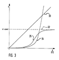
- FIG. 3 shows several possible functions of the correction value k which are stored in the read / write memory 22a as a function of the ratio of the red component to the brightness component of the color image signal or of the quotient R / (R + G) .
- the straight line 32 drawn in dashed lines corresponds to a static white balance correction, ie the correction value k 'is constant and does not depend on the ratio R / (R + G) from.
- the use of such a white balance correction would have the consequence that even an image with a small red component would already undergo a white balance correction and would therefore have a color cast outside the operating field or even at a large viewing distance where there is no red shift.
- the straight line 33 shows a linear dynamic function as it can be used as an application-specific correction function by the correction device according to the invention.
- the ratio of red / brightness increases or the ratio increases R / (R + G) of the image the correction value k is increased linearly.
- This correction value function is particularly advantageous, since the mucous membrane is not so strongly illuminated with a larger viewing distance and the red shift is therefore less than with a small viewing distance, where a strong red shift occurs depending on the application. The white balance is therefore only corrected to the extent that there is a shift towards red.
- functions 34 and 35 have a pronounced non-linear behavior.
- small amounts of red which, for example, are not caused by a red shift, are tolerated in the image, i.e. they cause no or only a small correction of the white balance.
- stronger red components such as those caused by a red shift through the mucous membrane, result in a stronger white balance correction than in the case of linear, dynamic behavior.
- curve 34 from a certain ratio R / (R + G) increases steadily, curve 35 has an asymptotic approximation to a constant correction value, for example, according to FIG. 3, to the correction value k ′ corresponding to straight line 32.
- FIG. 3 shows only examples of the functions of the correction value k. Which correction value function is ultimately stored or selected depends on the nature of the hollow organ being examined and on the selection made on the operating unit 21 or its keys 21a,... 21n by the examining person. Other dynamic profiles of the correction value k can therefore also be stored in the read-write memory 22a.
- the microprocessor 22e thus generates the correction values k for the color signals RW, GW and BW as a function of the measured quotient R / (R + G) and the correction value function selected from the read / write memory (FIG. 3), while the microprocessor 22e generates the respective correction values on the basis of look-up tables corresponding to the correction value functions stored in the read / write memory. This is much faster than a calculation.
- R / (R + G) are the video signals R and G at the input of integration and holding elements 22h, 22i and are integrated over a field, ie over 20 ms.
- V sync stores the voltage integrated via a field at the output of the integration and holding elements 22h, 22i. These voltages then correspond to the intensity of the red and green components of the color image.
- the positive edge of the vertical synchronization pulse V sync resets the integrator of the integration and holding elements 22h, 22i and triggers an interruption at the microprocessor 22e.
- the microprocessor 22e switches a multiplexer 22g to the output of the integration and holding element 22i.
- the voltage of the red channel is thus present at the input of an analog-digital converter 22f and is digitized there.
- This digitized value is temporarily stored in the microprocessor 22i.
- an approximate value of the brightness signal is calculated according to the sum R + G.
- the quotient of the new red component is then according to R / (R + G) calculated.
- the microprocessor 22e reads on the basis of the quotient thus calculated R / (R + G) the white balance corrections selected on the operating unit 21 from the look-up table in the read-write memory 22a.
- the microprocessor 22e may be the quotient R / (R + G) calculate the corresponding correction values k for each color by arithmetic operation, but this takes a longer computing time than reading from the look-up table.
- the read-in integration and conversion process described is repeated in the same way, except that the green channel G is now read in.
- the multiplexer 22g is switched over to the integration holding element 22h.
- the approximate value for the brightness component ie the sum R + G, is calculated again.
- the correction values k for each color are determined anew on the basis of the selected white balance correction function, or are read out from the look-up tables for the correction value functions stored in the random access memory.
- the red component and the green component are preferably detected offset by one field period and the digital value corresponding to their intensity is read into the microprocessor 22e.
- the correction voltage generators 22b, 22c and 22d represent digital-to-analog converters or digital potentiometers, they receive the digital correction values k corresponding to the individual color components from the microprocessor 22e and convert them into the correction voltages U RW , U GW and U BW , which correspond to the control inputs of the VCAs 18a, 18b and 18c are fed.
- the examination person handling the endoscope can also manually change the application-specific correction voltages to values that do not correspond to the values in the read / write memory 22a by pressing the keys 21a,... 21n of the operating unit 21.
- This manual change can also be reversed by actuating one of the keys 21a,... 21n, so that the correction values k corresponding to the specified functions are again generated at the output of the microprocessor 22e.
- FIG. 4 shows an auxiliary device for the white balance, which is carried out with the white balance device 17 shown in FIG. 1.
- This uses the auxiliary device to carry out a white balance called EWC (Endo White Control).
- EWC Endo White Control
- the endoscope 10 is inserted through an opening into a balancing aid 16 which is shaped like a balloon and has a white coating on the inside. This ensures that the disturbing ambient light 4 cannot mix with the endoscopic illuminating light and can lead to an incorrect result.
- the difference between the components used in an endoscopic system can now be compensated with the adjustment aid 16 and the white balance device 17, as is known from EP-0530738A. This ensures that a white field of view in front of the endoscope is also displayed in white on the monitor.
Landscapes
- Engineering & Computer Science (AREA)
- Health & Medical Sciences (AREA)
- Life Sciences & Earth Sciences (AREA)
- Multimedia (AREA)
- Signal Processing (AREA)
- Surgery (AREA)
- Radiology & Medical Imaging (AREA)
- Heart & Thoracic Surgery (AREA)
- Optics & Photonics (AREA)
- Pathology (AREA)
- Biophysics (AREA)
- Physics & Mathematics (AREA)
- Biomedical Technology (AREA)
- Nuclear Medicine, Radiotherapy & Molecular Imaging (AREA)
- Medical Informatics (AREA)
- Molecular Biology (AREA)
- Animal Behavior & Ethology (AREA)
- General Health & Medical Sciences (AREA)
- Public Health (AREA)
- Veterinary Medicine (AREA)
- Processing Of Color Television Signals (AREA)
- Endoscopes (AREA)
Applications Claiming Priority (2)
| Application Number | Priority Date | Filing Date | Title |
|---|---|---|---|
| DE4431491 | 1994-09-03 | ||
| DE4431491A DE4431491C1 (de) | 1994-09-03 | 1994-09-03 | Verfahren und Vorrichtung zur Korrektur des Weißabgleichs eines Videofarbbildsignals |
Publications (3)
| Publication Number | Publication Date |
|---|---|
| EP0700217A2 true EP0700217A2 (fr) | 1996-03-06 |
| EP0700217A3 EP0700217A3 (fr) | 1998-12-02 |
| EP0700217B1 EP0700217B1 (fr) | 2001-11-07 |
Family
ID=6527396
Family Applications (1)
| Application Number | Title | Priority Date | Filing Date |
|---|---|---|---|
| EP95112637A Expired - Lifetime EP0700217B1 (fr) | 1994-09-03 | 1995-08-11 | Procédé et appareil pour la correction de l'équilibre du blanc d'un signal vidéo couleur |
Country Status (3)
| Country | Link |
|---|---|
| US (1) | US5570129A (fr) |
| EP (1) | EP0700217B1 (fr) |
| DE (2) | DE4431491C1 (fr) |
Families Citing this family (12)
| Publication number | Priority date | Publication date | Assignee | Title |
|---|---|---|---|---|
| US6147707A (en) * | 1996-02-06 | 2000-11-14 | Canon Kabushiki Kaisha | Method and apparatus for gain adjustment of an image sensor |
| US6147705A (en) * | 1996-08-20 | 2000-11-14 | Welch Allyn Inc. | Apparatus and method for video colposcope with electronic green filter |
| WO1998053615A1 (fr) * | 1997-05-22 | 1998-11-26 | Koninklijke Philips Electronics N.V. | Commande d'equilibrage des blancs |
| US6577408B1 (en) * | 1999-02-05 | 2003-06-10 | Hewlett-Packard Development Company, L.P. | Method and apparatus for correcting blue drift in an image scanner |
| US7162078B2 (en) * | 2002-12-20 | 2007-01-09 | Fast Link Communication Corp. | Automatic white balance correction method for image capturing apparatus |
| JP4294440B2 (ja) | 2003-10-30 | 2009-07-15 | オリンパス株式会社 | 画像処理装置 |
| JP4804062B2 (ja) * | 2005-07-29 | 2011-10-26 | オリンパス株式会社 | 内視鏡システム |
| US20090105543A1 (en) * | 2007-10-19 | 2009-04-23 | Miller Eric C | Endoscope Lens Cleaner |
| JP5604248B2 (ja) * | 2010-09-28 | 2014-10-08 | 富士フイルム株式会社 | 内視鏡画像表示装置 |
| US9319636B2 (en) | 2012-12-31 | 2016-04-19 | Karl Storz Imaging, Inc. | Video imaging system with multiple camera white balance capability |
| CN106023929B (zh) * | 2016-07-20 | 2018-08-24 | 深圳市华星光电技术有限公司 | 显示装置的白平衡调整方法及其系统 |
| JP7491711B2 (ja) * | 2020-03-26 | 2024-05-28 | 株式会社フジクラ | 内視鏡 |
Citations (3)
| Publication number | Priority date | Publication date | Assignee | Title |
|---|---|---|---|---|
| US4831437A (en) | 1987-08-11 | 1989-05-16 | Olympus Optical Co., Ltd. | Video endoscope system provided with color balance adjusting means |
| US5111281A (en) | 1987-09-28 | 1992-05-05 | Kabushiki Kaisha Toshiba | Color correction device for an endoscope |
| EP0530738A2 (fr) | 1991-09-02 | 1993-03-10 | Matsushita Electric Industrial Co., Ltd. | Circuit automatique de température de couleur |
Family Cites Families (6)
| Publication number | Priority date | Publication date | Assignee | Title |
|---|---|---|---|---|
| JPS61128693A (ja) * | 1984-11-28 | 1986-06-16 | Matsushita Electric Ind Co Ltd | カラ−カメラ |
| JPH01231586A (ja) * | 1988-03-11 | 1989-09-14 | Mitsubishi Electric Corp | 自動ホワイトバランス装置 |
| JPH031791A (ja) * | 1989-05-30 | 1991-01-08 | Sony Corp | オートホワイトバランス回路 |
| JPH03154590A (ja) * | 1989-11-13 | 1991-07-02 | Fuji Photo Film Co Ltd | カメラ |
| US5223921A (en) * | 1990-04-27 | 1993-06-29 | Sanyo Electric Co., Ltd. | White balance adjusting apparatus for automatically adjusting white balance on the basis of a color information signal obtained from an image-sensing device |
| US5177599A (en) * | 1990-07-23 | 1993-01-05 | Hitachi, Ltd. | White balance controller for an image pick-up apparatus including an abnormality detector |
-
1994
- 1994-09-03 DE DE4431491A patent/DE4431491C1/de not_active Expired - Fee Related
-
1995
- 1995-08-11 DE DE59509800T patent/DE59509800D1/de not_active Expired - Fee Related
- 1995-08-11 EP EP95112637A patent/EP0700217B1/fr not_active Expired - Lifetime
- 1995-08-30 US US08/521,155 patent/US5570129A/en not_active Expired - Fee Related
Patent Citations (3)
| Publication number | Priority date | Publication date | Assignee | Title |
|---|---|---|---|---|
| US4831437A (en) | 1987-08-11 | 1989-05-16 | Olympus Optical Co., Ltd. | Video endoscope system provided with color balance adjusting means |
| US5111281A (en) | 1987-09-28 | 1992-05-05 | Kabushiki Kaisha Toshiba | Color correction device for an endoscope |
| EP0530738A2 (fr) | 1991-09-02 | 1993-03-10 | Matsushita Electric Industrial Co., Ltd. | Circuit automatique de température de couleur |
Also Published As
| Publication number | Publication date |
|---|---|
| DE59509800D1 (de) | 2001-12-13 |
| EP0700217B1 (fr) | 2001-11-07 |
| EP0700217A3 (fr) | 1998-12-02 |
| US5570129A (en) | 1996-10-29 |
| DE4431491C1 (de) | 1996-01-18 |
Similar Documents
| Publication | Publication Date | Title |
|---|---|---|
| DE4136034C2 (fr) | ||
| DE10164297B4 (de) | Elektronisches Endoskopsystem | |
| DE10055725B4 (de) | Elektronisches Endoskopsystem | |
| DE3818125C2 (fr) | ||
| DE10101064B4 (de) | Elektronisches Endoskopsystem | |
| DE602004008376T2 (de) | Elektronische Vorrichtung für Endoskop | |
| DE102008053741A1 (de) | Elektronisches Endoskopsystem und Signalprozessor | |
| DE3922679A1 (de) | Endoskopvorrichtung | |
| DE102009032249B4 (de) | Signalverarbeitungsvorrichtung für ein elektronisches Endoskop und elektronisches Endoskopsystem | |
| EP0700217B1 (fr) | Procédé et appareil pour la correction de l'équilibre du blanc d'un signal vidéo couleur | |
| DE3523514C3 (de) | Digitales Röntgen-Untersuchungsgerät | |
| DE3432391A1 (de) | Endoskopanordnung | |
| DE3743095C2 (fr) | ||
| WO2011076159A2 (fr) | Procédé d'examen stroboscopique de phénomènes récurrents et agencement pour la mise en oeuvre de ce procédé | |
| DE19712434C2 (de) | Verfahren zum Abgleich eines Videosignals | |
| DE3106627C2 (fr) | ||
| DE19529367C2 (de) | Vorrichtung zur Farbtonkorrektur bei von einer Videokamera aufgenommenen Farbbildern | |
| DE10325382A1 (de) | Verfahren und Vorrichtung zum Visualisieren von medizinischen Patientendaten auf einer medizinischen Anzeigeeinheit | |
| WO2001052522A2 (fr) | Procede et dispositif de modification de la saturation chromatique d'images saisies electroniquement | |
| DE19529366C2 (de) | Vorrichtung zur Farbtonkorrektur bei von einer Videokamera aufgenommenen Farbbildern | |
| DE102007022958A1 (de) | Endoskopprozessor, Computerprogrammprodukt, Endoskopsystem und Endoskopbild-Wiedergabegerät | |
| CH694684A5 (de) | Verfahren und Vorrichtung zur Bestimmung von Zahnfarben. | |
| DE102021130790B4 (de) | Medizinische Bildgebungsvorrichtung sowie Verfahren zum Kalibrieren einer medizinischen Bildgebungsvorrichtung | |
| DE102006033088B3 (de) | Verfahren zur automatischen Regelung der Helligkeit und/oder des Kontrastes von Bildschirmen oder Displays | |
| DE4208454A1 (de) | Endoskop mit farbtreuer bilddarstellung |
Legal Events
| Date | Code | Title | Description |
|---|---|---|---|
| PUAI | Public reference made under article 153(3) epc to a published international application that has entered the european phase |
Free format text: ORIGINAL CODE: 0009012 |
|
| AK | Designated contracting states |
Kind code of ref document: A2 Designated state(s): DE FR GB IT |
|
| PUAL | Search report despatched |
Free format text: ORIGINAL CODE: 0009013 |
|
| AK | Designated contracting states |
Kind code of ref document: A3 Designated state(s): DE FR GB IT |
|
| 17P | Request for examination filed |
Effective date: 19990106 |
|
| GRAG | Despatch of communication of intention to grant |
Free format text: ORIGINAL CODE: EPIDOS AGRA |
|
| RTI1 | Title (correction) |
Free format text: METHOD AND APPARATUS FOR CORRECTING THE WHITE BALANCE OF A COLOUR VIDEO SIGNAL |
|
| GRAG | Despatch of communication of intention to grant |
Free format text: ORIGINAL CODE: EPIDOS AGRA |
|
| GRAH | Despatch of communication of intention to grant a patent |
Free format text: ORIGINAL CODE: EPIDOS IGRA |
|
| 17Q | First examination report despatched |
Effective date: 20010228 |
|
| RTI1 | Title (correction) |
Free format text: METHOD AND APPARATUS FOR CORRECTING THE WHITE BALANCE OF A COLOUR VIDEO SIGNAL |
|
| GRAH | Despatch of communication of intention to grant a patent |
Free format text: ORIGINAL CODE: EPIDOS IGRA |
|
| GRAA | (expected) grant |
Free format text: ORIGINAL CODE: 0009210 |
|
| AK | Designated contracting states |
Kind code of ref document: B1 Designated state(s): DE FR GB IT |
|
| REF | Corresponds to: |
Ref document number: 59509800 Country of ref document: DE Date of ref document: 20011213 |
|
| REG | Reference to a national code |
Ref country code: GB Ref legal event code: IF02 |
|
| GBT | Gb: translation of ep patent filed (gb section 77(6)(a)/1977) |
Effective date: 20020213 |
|
| PLBE | No opposition filed within time limit |
Free format text: ORIGINAL CODE: 0009261 |
|
| STAA | Information on the status of an ep patent application or granted ep patent |
Free format text: STATUS: NO OPPOSITION FILED WITHIN TIME LIMIT |
|
| 26N | No opposition filed | ||
| PGFP | Annual fee paid to national office [announced via postgrant information from national office to epo] |
Ref country code: FR Payment date: 20050630 Year of fee payment: 11 |
|
| PGFP | Annual fee paid to national office [announced via postgrant information from national office to epo] |
Ref country code: GB Payment date: 20050729 Year of fee payment: 11 |
|
| PGFP | Annual fee paid to national office [announced via postgrant information from national office to epo] |
Ref country code: DE Payment date: 20051010 Year of fee payment: 11 |
|
| PGFP | Annual fee paid to national office [announced via postgrant information from national office to epo] |
Ref country code: IT Payment date: 20060831 Year of fee payment: 12 |
|
| PG25 | Lapsed in a contracting state [announced via postgrant information from national office to epo] |
Ref country code: DE Free format text: LAPSE BECAUSE OF NON-PAYMENT OF DUE FEES Effective date: 20070301 |
|
| GBPC | Gb: european patent ceased through non-payment of renewal fee |
Effective date: 20060811 |
|
| REG | Reference to a national code |
Ref country code: FR Ref legal event code: ST Effective date: 20070430 |
|
| PG25 | Lapsed in a contracting state [announced via postgrant information from national office to epo] |
Ref country code: GB Free format text: LAPSE BECAUSE OF NON-PAYMENT OF DUE FEES Effective date: 20060811 |
|
| PG25 | Lapsed in a contracting state [announced via postgrant information from national office to epo] |
Ref country code: FR Free format text: LAPSE BECAUSE OF NON-PAYMENT OF DUE FEES Effective date: 20060831 |
|
| PG25 | Lapsed in a contracting state [announced via postgrant information from national office to epo] |
Ref country code: IT Free format text: LAPSE BECAUSE OF NON-PAYMENT OF DUE FEES Effective date: 20070811 |