EP0700202B1 - Vorrichtung zur Bildstabilisierung - Google Patents
Vorrichtung zur Bildstabilisierung Download PDFInfo
- Publication number
- EP0700202B1 EP0700202B1 EP95113618A EP95113618A EP0700202B1 EP 0700202 B1 EP0700202 B1 EP 0700202B1 EP 95113618 A EP95113618 A EP 95113618A EP 95113618 A EP95113618 A EP 95113618A EP 0700202 B1 EP0700202 B1 EP 0700202B1
- Authority
- EP
- European Patent Office
- Prior art keywords
- lock
- vibration
- photo
- frame
- taking lens
- Prior art date
- Legal status (The legal status is an assumption and is not a legal conclusion. Google has not performed a legal analysis and makes no representation as to the accuracy of the status listed.)
- Expired - Lifetime
Links
- 230000000087 stabilizing effect Effects 0.000 title claims description 6
- 230000001105 regulatory effect Effects 0.000 claims description 16
- 239000003381 stabilizer Substances 0.000 claims description 12
- 230000004044 response Effects 0.000 claims description 6
- 239000007788 liquid Substances 0.000 claims description 5
- 239000000126 substance Substances 0.000 claims description 2
- 238000012937 correction Methods 0.000 description 11
- 230000003287 optical effect Effects 0.000 description 8
- 238000010276 construction Methods 0.000 description 6
- 230000000694 effects Effects 0.000 description 6
- 230000002093 peripheral effect Effects 0.000 description 4
- 229910000906 Bronze Inorganic materials 0.000 description 2
- OAICVXFJPJFONN-UHFFFAOYSA-N Phosphorus Chemical compound [P] OAICVXFJPJFONN-UHFFFAOYSA-N 0.000 description 2
- 230000003321 amplification Effects 0.000 description 2
- 239000010974 bronze Substances 0.000 description 2
- 230000001276 controlling effect Effects 0.000 description 2
- KUNSUQLRTQLHQQ-UHFFFAOYSA-N copper tin Chemical compound [Cu].[Sn] KUNSUQLRTQLHQQ-UHFFFAOYSA-N 0.000 description 2
- 238000013461 design Methods 0.000 description 2
- 238000001514 detection method Methods 0.000 description 2
- 230000006870 function Effects 0.000 description 2
- 230000002401 inhibitory effect Effects 0.000 description 2
- 239000000463 material Substances 0.000 description 2
- 238000003199 nucleic acid amplification method Methods 0.000 description 2
- 230000035939 shock Effects 0.000 description 2
- 229910001220 stainless steel Inorganic materials 0.000 description 2
- 239000010935 stainless steel Substances 0.000 description 2
- 238000006243 chemical reaction Methods 0.000 description 1
- 230000001419 dependent effect Effects 0.000 description 1
- 238000011161 development Methods 0.000 description 1
- 230000018109 developmental process Effects 0.000 description 1
- 239000011521 glass Substances 0.000 description 1
- 238000003780 insertion Methods 0.000 description 1
- 230000037431 insertion Effects 0.000 description 1
- 238000000034 method Methods 0.000 description 1
- 230000007935 neutral effect Effects 0.000 description 1
- 230000002265 prevention Effects 0.000 description 1
- 230000000630 rising effect Effects 0.000 description 1
Images






Classifications
-
- H—ELECTRICITY
- H04—ELECTRIC COMMUNICATION TECHNIQUE
- H04N—PICTORIAL COMMUNICATION, e.g. TELEVISION
- H04N23/00—Cameras or camera modules comprising electronic image sensors; Control thereof
- H04N23/60—Control of cameras or camera modules
- H04N23/68—Control of cameras or camera modules for stable pick-up of the scene, e.g. compensating for camera body vibrations
-
- H—ELECTRICITY
- H04—ELECTRIC COMMUNICATION TECHNIQUE
- H04N—PICTORIAL COMMUNICATION, e.g. TELEVISION
- H04N23/00—Cameras or camera modules comprising electronic image sensors; Control thereof
- H04N23/60—Control of cameras or camera modules
- H04N23/68—Control of cameras or camera modules for stable pick-up of the scene, e.g. compensating for camera body vibrations
- H04N23/681—Motion detection
- H04N23/6812—Motion detection based on additional sensors, e.g. acceleration sensors
-
- H—ELECTRICITY
- H04—ELECTRIC COMMUNICATION TECHNIQUE
- H04N—PICTORIAL COMMUNICATION, e.g. TELEVISION
- H04N23/00—Cameras or camera modules comprising electronic image sensors; Control thereof
- H04N23/60—Control of cameras or camera modules
- H04N23/68—Control of cameras or camera modules for stable pick-up of the scene, e.g. compensating for camera body vibrations
- H04N23/682—Vibration or motion blur correction
- H04N23/685—Vibration or motion blur correction performed by mechanical compensation
- H04N23/686—Vibration or motion blur correction performed by mechanical compensation with a variable apex prism
Definitions
- This invention relates to a device for stabilizing an image, according to the preamble of claim 1 such as an image vibration correcting device used in an image pickup apparatus such as a television camera or a video camera and capable of obtaining a stable image free of image vibration when disturbance vibration is applied to the image pickup apparatus.
- an image vibration correcting device used in an image pickup apparatus such as a television camera or a video camera and capable of obtaining a stable image free of image vibration when disturbance vibration is applied to the image pickup apparatus.
- variable angle prism which, as shown in Figure 11 of the accompanying drawings, is disposed on the photo-taking optical path of a photo-taking lens and inclines the photo-taking optical path by the relative tilting of a pair of transparent plates having transparent liquid interposed therebetween to thereby correct the vibration of an image field.
- two transparent plates 1 and 2 each comprising a glass plate or the like have their outer peripheral frame members 3 and 4 sealed by bellows-like film 5, and this hermetically sealed space is filled with liquid of a high refractive index, and a variable angle prism 6 is constituted by these.
- the frame member 3 has a flattened coil 7 secured to one end thereof, and permanent magnets 8 and yokes 9, 10 opposed to each other with the coil 7 interposed therebetween are disposed on the opposite sides of the coil 7 to thereby constitute driving means 11 comprising a closed magnetic circuit.
- the frame member 3 also is provided with an arm 13 having a slit 12, and a light emitting element 14 and a light receiving element 15 are disposed on the opposite sides of the arm 13 in opposed relationship with each other, and a beam of light emitted from the light emitting element 14 may pass through the slit 12, and thereafter may be applied to the light receiving element 15.
- the light emitting element 14 is, for example, an infrared light emitting element emitting infrared light such as IRED, and the light receiving element 15 is, for example, a photoelectric conversion element such as PSD of which the output is varied by the spot position of the received beam of light.
- IRED infrared light emitting element emitting infrared light
- PSD photoelectric conversion element
- the frame member 4 is also provided with an arm 17 having a slit 16, and although not shown, there are disposed a flattened coil, permanent magnets, yokes, a light emitting element and a light receiving element similar to those on the frame member 3 side.
- vibration detectors 18 and 19 as vibration detecting means are mounted with respect to the pitch direction P and the yaw direction P so as to be capable of detecting the amounts of vibration of the entire apparatus in the pitch direction P and the yaw direction Y, and there are provided a control circuit 20 as control means comprised of an A/D converter, a D/A converter, a CPU, a memory, etc. and receiving as inputs the detection signals of the vibration detectors 18 and 19 and controlling a system, and a coil driving circuit 21 for supplying an electric current to the coil 7 on the frame member 3 side and the coil on the frame member 4 side in accordance with the command of the control circuit 20.
- a control circuit 20 as control means comprised of an A/D converter, a D/A converter, a CPU, a memory, etc. and receiving as inputs the detection signals of the vibration detectors 18 and 19 and controlling a system
- a coil driving circuit 21 for supplying an electric current to the coil 7 on the frame member 3 side and the coil on the frame member 4 side in
- the frame members 3 and 4 are supported on a frame, not shown, by a pitch shaft P and a yaw shaft Y, and a lock pin 24 protruding to the outside in the direction of the pitch shaft P is secured to the outer peripheral surface of the frame member 4.
- a lock knob 25 formed with a V-shaped recess for receiving the lock pin 24 is provided on the frame and also, a limit switch 26 for detecting the operated position of the lock knob 25 is provided.
- a lock pin 24, a lock knob 25 and a limit switch 26 are also disposed on the frame member 3 centering around the direction of the yaw shaft Y to lock the frame member 3 in its neutral position.
- the vibration detectors 18 and 19 detect the vibration and the signals thereof are inputted to the control circuit 20, whereby the vertical angle of the variable angle prism 6 necessary to eliminate the vibration is calculated.
- the fluctuation of the angles of rotation of the opposed transparent plates 1 and 2 about the shafts P and Y causes a fluctuation to the spot position on the light receiving surface when the beam of light emitted from the light emitting element 14 is transmitted through the slits 12 and 16 formed in the arms 14 and 17 of the frame members 3 and 4 rotated with the opposed transparent plates 1 and 2 and enters the light receiving element 15.
- the light receiving element 15 transmits to the control circuit 20 an output conforming to the amount of movement of the spot thereon, i.e., the magnitude of the vertical angle of the variable angle prism 6.
- This control circuit 20 calculates the difference between the magnitude of the aforementioned calculated vertical angle and the magnitude of the vertical angle at the present point of time and transmits it to the coil driving circuit 21.
- This coil driving circuit 21 supplies the coil 8 with a driving current conforming to a coil driving command signal.
- variable angle prism 6 effects rotative movement about the shafts X and Y by the coil 8 and is deformed so as to coincide with the magnitude of the aforementioned calculated vertical angle. That is, the variable angle prism 6 is designed to effect the correction control of vibration by feedback control using the value of the vertical angle calculated so as to correct vibration as a reference signal and using the value of the current vertical angle as a feedback signal.
- the generic prior art EP-A-0 540 046 describes a device wherein, when vibration correction is not effected, that is when the vibration correction control apparatus is turned OFF, the lock knob 25 is moved upwardly and the lock pin 24 is held in the recess at the upper end of the lock knob 25. Thereupon, the frame member 4 becomes unable to rotate relative to the yaw shaft Y and is locked in the yaw direction.
- the lock knob 25 is moved up to its lock position, the limit switch 26 is operated and the operation is transmitted to the coil driving circuit 21 and in conformity therewith, the supply of electric power to the coil of the frame member 4 is stopped.
- the pitch direction P is likewise locked.
- variable angle prism 6 generally disposed forwardly of the front lens portion of the high-magnification photo-taking lens need be made large when the effective beam of light of the lens is taken into consideration. Accordingly, the driving means for tilting the transparent plates 1 and 2 of the variable angle prism 6 also becomes bulky and the image vibration correcting device tends to become bulky. Further, the balkiness of the device including the photo-taking lens and an increase in the weight thereof result.
- the image stabilizing device can be removed from an objective lens during ordinary photographing in which the vibration prevention function is not performed, and prevent the removed device from being damaged at this time by a shock being inadvertently applied thereto from the outside.
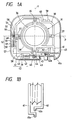
- Figures 1A and 1B show the construction of a first embodiment of the present invention.
- Figures 2A and 2B are side views in which a portion corresponding to a photo-taking lens is cut away.
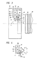
- Figure 3 is a cross-sectional view of the first embodiment before mounted on the photo-taking lens taken along the line A-A of Figure 2A.
- Figure 4 is a cross-sectional view of the first embodiment before mounted on the photo-taking lens taken along the line B-B of Figure 2A.
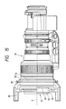
- Figure 5 is a cross-sectional view of the first embodiment when mounted on the photo-taking lens taken along the line A-A of Figure 2A.
- Figure 6 is a cross-sectional view of the first embodiment when mounted on the photo-taking lens taken along the line B-B of Figure 2A.
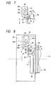
- Figure 7 is a cross-sectional view of the first embodiment when mounted on the photo-taking lens taken along the line B-B of Figure 2A and showing a state in which a lock is released.
- Figure 9 shows the construction of a second embodiment of the present invention.
- Figure 10 is a cross-sectional view taken along the line C-C of Figure 9.
- Figure 11 is an exploded perspective view of an example of the conventional art.
- Figure 12 is a side view of the second embodiment as it is mounted on the photo-taking lens and in which a portion thereof is cut away.
- Figure 13 is a cross-sectional view taken along the line A-A of Figure 12.
- Figure 14 is a side view of a variation of the second embodiment as it is mounted on the photo-taking lens and in which a portion thereof is cut away.
- Figure 15 is a side view of an image stabilizer as it is mounted on the photo-taking lens and in which a portion thereof is cut away.
- Figure 16 is a side view of an image stabilizer as it is mounted on the photo-taking lens and in which a portion thereof is cut away.
- Figure 17 is a cross-sectional view taken along the line B-B of Figure 16.
- FIGS 1A and 1B show the construction of a first embodiment.
- the frame 30 of a device according to this embodiment is of an open square box shape and carries a variable angle prism and electronic parts thereon. Also, it has a mounting and dismounting mechanism with respect to a photo-taking lens as will be described later.
- variable angle prism 31 is constructed such that as shown in Figures 2A and 2B, two circular front and back transparent plates 32 and 33 have their outer peripheries sealed by bellows-like film 34 and this hermetically sealed space is filled of liquid of a high refractive index, and the film 34 is formed into two to three steps of bellows so that the variable angle prism 31 may be inclined in any direction and have a vertical angle.
- a frame member 36 is supported on a frame 30 by a diametral yaw shaft 35 provided on the outer periphery thereof
- a frame member 38 is supported on the frame 30 by a diametral pitch shaft 37 provided on the outer periphery and orthogonal to the yaw shaft 35
- the variable angle prism 31 has its transparent plate 32 side held by the frame member 36 and has its transparent plate 33 side held by the frame member 38
- the transparent plates 32 and 33 are rotatable about the yaw shaft 35 and the pitch shaft 37.
- a flattened coil 39 orthogonal to an arm portion extending in a direction parallel to the yaw shaft 35 is secured to the tip end of the arm portion, and a permanent magnet 40 and yokes 41 and 42 having their surfaces opposed to one another are disposed on the opposite sides of the coil 39, whereby driving means 43 by a closed magnetic circuit is constituted.
- an arm 45 having a slit 44 is provided at the tip end of the arm portion on the side opposite to the flattened coil 39, and a light emitting element 46 and a light receiving element 47 are disposed in opposed relationship with each other with the arm 45 interposed therebetween.
- Driving means 52 by a closed magnetic circuit provided by a coil 48, a permanent magnet 49 and yokes 50, 51 similar to those provided on the frame member 36 is constructed also on the other frame member 38, and an arm 54 having a slit 53, a light emitting element 55 and a light receiving element 56 are disposed.
- vibration detectors 57 and 58 as vibration detecting means with respect to a pitch direction P and a yaw direction Y are mounted so as to be capable of detecting the amounts of hand vibration of the entire apparatus in the pitch direction and the yaw direction.
- a control circuit 59 comprised of an A/D converter, a D/A converter, a CPU, a memory, etc. and receiving as inputs the detection signals of the vibration detectors 57 and 58 and controlling a system and a coil driving circuit 60 for supplying an electric current to the coils 39 and 48 in accordance with the command of the control circuit 59 are mounted on the frame 30.
- Support arms 61 and 62 having their tip ends bent at a right angle and parallel to each other, as shown in Figure 1B, are provided on the outer peripheries of the frame members 36 and 38, and lock pins 61a and 62a are attached to the tip ends thereof.
- a support stand 63 having regulating edges 63a on the opposite sides thereof as shown in Figure 3 is provided on the frame 30, and a lock plate 66 in which cut-out portions 64 and 65 each having a V-shaped portion in the upper portion thereof are disposed in series has its opposite sides guided by the regulating edges 63a and is supported on the support stand 63 for sliding movement in the directions of arrows c and d, and the lock pins 61a and 62a are inserted in the cut-out portions 64 and 65, respectively.
- This lock plate 66 is biased in the direction of arrow c by a tension spring 67 having one end thereof attached to the projection of the frame 30.
- a changeover pin 68 is protrudely provided in parallelism to the lock pin 62 on the right side of the lock plate 66 as viewed in Figure 3.
- an interlocking lever 70 which extends from a shaft 69 rising in a direction parallel to the lock pin, in the direction of arrow c orthogonal to the direction of mounting with respect to a photo-taking lens, and which is pivotable about the shaft 69.
- This lever 70 has its bent tip end biased in the direction of arrow b which is the lens insertion side, by a tension spring 71 having one end thereof attached to the projection of the frame 30.
- a stopper 73 having a pin 72 striking in a direction orthogonal to the interlocking lever 70 is supported integrally with the interlocking lever 70, and is biased in the direction of arrow a opposite to the direction of arrow b by a push-up spring 74.
- a lock lever 76 pivotally supported on a shaft 75 provided on the frame 30 as shown in Figure 4, and a changeover lever 77 interlocking with the lock lever 76 and bearing against the changeover pin 68.
- the image vibration correcting device thus constructed is mounted on a photo-taking lens 80 as shown in Figure 5 when vibration correction during photographing on a vehicle or a helicopter is necessary.
- the tip end of the interlocking lever 70 strikes against the fore lens barrel portion 81 of the photo-taking lens 80 and the interlocking lever 70 becomes substantially parallel to the lock plate 66.
- the stopper 73 strikes against the lock plate 66 and is pushed in the direction of arrow e against the biasing force of the tension spring 74.
- the frame members 36 and 38 remain in a state in which the lock pins 61a and 62a are in the V-shaped portions of the lock plate 66 and rotation is restricted, that is, a state in which the driving means for correcting vibration is locked.
- the lock lever 76 and the changeover lever 77 are not operated.
- the vibration correcting device even if mounted on the photo-taking lens, has its operation inhibited unless the lock lever 76 is operated.
- the stopper 73 is pushed out in the direction of arrow c with respect to the lock plate 66 by the push-up spring 74, as shown in Figure 8, and bears against the lock plate 66 to thereby regulate the movement thereof in the direction of arrow c. Thereby, the driving means for correcting vibration is released.
- the vibration detectors 57 and 58 of the image vibration correcting device When vibration occurs to the entire photographing apparatus, the vibration detectors 57 and 58 of the image vibration correcting device output signals proportional to the magnitude of the vibration. These signals are inputted to the control circuit 59, in which they are multiplied by an appropriate multiplier and the magnitude of a vertical angle necessary to eliminate the vibration is calculated.
- the fluctuation of the angles of rotation of the opposed transparent plates 32 and 33 about the shafts 35 and 37 causes the movement of the spot positions on the light receiving surfaces when the beams of light emitted from the light emitting elements 46 and 55 are transmitted through the slits 44 and 53 formed in the arms 45 and 54 of the frame members 36 and 38 rotated with the opposed transparent plates 32 and 33 and enter the light receiving elements 47 and 56.
- the light receiving elements 47 and 56 transmit to the control circuit 59 signals conforming to the amounts of movement of the spots, i.e., the magnitude of the vertical angle of the variable angle prism 31.
- This control circuit 59 calculates the difference between the magnitude of the aforementioned calculated vertical angle and the magnitude of the vertical angle at the present point of time, and transmits to the coil driving circuit 60 the result of this difference having been multiplied by a predetermined amplification factor as the drive command signal of the coils 39 and 48.
- This coil driving circuit 60 supplies the coils 39 and 48 with a driving current conforming to the coil drive command signal and generates a coil driving force.
- variable angle prism 31 effects rotative movement about the shafts 35 and 37 by this coil driving force and is deformed so as to coincide with the magnitude of the aforementioned calculated vertical angle. That is, the variable angle prism 31 effects vibration correction by feedback control using the value of the vertical angle calculated so as to correct vibration as a reference signal and using the value of the current vertical angle as a feedback signal.
- the lock pins 61a and 62a are regulated by the lock plate 66 and the driving means for correcting vibration is locked.
- the movement thereof in response to the removal of the stabilizer, the movement thereof is automatically regulated and the stabilizer can be obviated from being damaged by any unexpected shock.
- Figures 9 and 10 show the construction of a second embodiment of the present invention.
- the interlocking lever 70, the lock lever 76, the changeover lever 77, etc. are eliminated, and a light emitting element 90 and a light receiving element 91 opposed to each other with the fore lens barrel portion 81 of the photo-taking lens 80 interposed therebetween are disposed.
- the stopper 73 is supported for movement toward and away from the lock plate 66 by a stopper bed 92 having a rack, and a motor 94 having a gear 93 meshing with the rack is provided on the frame 30.
- the interlocking lever 70 is interlocked to the fore lens barrel portion 81 of the photo-taking lens 80, but alternatively, it may be interlocked to the operating grip 82 of the photo-taking lens 80.
- the frame 30 is mounted in a groove 72 formed in the outer periphery of the fore lens barrel portion 71 of a photo-taking lens 70, by a lock ring 61 secured to the frame 30, the lock ring 61 is formed of a springy material such as phosphor bronze or stainless steel, the ends 61a 1 , 61b 1 and 61c 1 thereof are secured to the frame 30 by screws and are disposed at equal intervals along the groove 72 toward the photo-taking lens 70, and the lock ring 60 has three arcuate pieces 61a, 61b and 61c as shown in Figure 13 which are deformable in the diametral directions b.
- the frame 30 has apertures at three locations and the other end portions of the arcuate pieces 61a, 61b and 61c are inserted in these apertures so as to slide on the cam surface of a lock cam 62.
- Three cut-ins 62a, 62b and 62c corresponding to the arcuate pieces 61a, 61b and 61c and gradually becoming deeper in the direction of arrow c are formed in the inner peripheral surface of the lock cam 62, and the lock cam 62 has an outwardly protruding lever portion 62d, and a recess 63 is formed in that side of this lever portion 62d in the direction of arrow c.
- a hold-down ring 64 for regulating the movement of the lock cam 62 in the direction of the optical axis is provided on the frame 30.
- an anti-slippage ring 65 having on its side adjacent to the photo-taking lens 70 a ring formed of a springy material such as phosphor bronze or stainless steel has its other side secured to the frame 30, and an anti-slippage lever 66 having a cam for deforming the anti-slippage ring 65 is provided on the outer periphery of the anti-slippage ring 65, and with the aid of this anti-slippage lever 66, the anti-slippage ring 65 may come into an inclined portion 73 provided on the fore lens barrel portion 71 and becoming smaller in diameter toward the photo-taking lens, from the diametral direction b thereof.
- the anti-slippage lever 66 is formed with a convex portion 66a adapted to be engaged with a recess 63 in a lever portion 62d only when the lock cam rotates in the direction of arrow c. Further, a hold-down ring 67 having one side thereof secured to the frame 30 and regulating the movement of the anti-slippage ring 65 in the direction of the optical axis a is provided on that side of the anti-slippage ring 65 which is adjacent to the photo-taking lens 70.
- the frame 30 is fitted onto the photo-taking lens 70 and the lock ring 61 is adjusted to the position of the groove 72 in the fore lens barrel portion 71, whereafter the lock cam 62 is rotated in the direction of arrow c.
- the arcuate pieces 61a, 61b and 61c of the lock ring 61 are pushed by the inclined surfaces of the cut-ins 62a, 62b and 62c of the lock cam 62 and are deformed in the diametral directions b, whereby the lock ring 61 is closely fixed to the groove 72 in the fore lens barrel portion 71.
- the frame 30 having the lock ring 61 secured thereto is then fixed to the photo-taking lens 70, and the image vibration correcting device is also fixed.
- the convex portion 66a of the anti-slippage lever 66 comes into engagement with the recess 63 formed in the lever portion 62d of the lock cam 62 and the anti-slippage lever 66 is also moved in the direction of arrow c, but the anti-slippage lever 66, like the lock cam 62, has a cam, by which the anti-slippage ring 65 is deformed so as to come into the inclined portion 73 of the fore lens barrel portion 71 from the diametral direction b.
- the anti-slippage lever 66 is interlocked with the lock cam 62 in the rotation in the direction of arrow c, but is not interlocked with the lock cam 62 in a direction opposite to the direction of arrow c, i.e., a direction to the release the fixing of the frame 30 to the photo-taking lens 70, because the convex portion 66a comes off the recess 63.
- the image vibration correcting device will not fall off from the photo-taking lens 70 because the movement of the frame 30 in the direction of the optical axis is regulated by the anti-slippage ring 65.
- the vibration detectors 57 and 58 output signals proportional to the magnitude of vibration when vibration occurs to the entire photographing apparatus. These signals are inputted to the control circuit 59 and are multiplied by an appropriate multiplier, and the magnitude of the vertical angle necessary to eliminate the vibration is calculated.
- the fluctuation of the angles of rotation of the opposed transparent plates 32 and 33 about the yaw shaft 35 i.e., the vertical angles of the variable angle prism in the pitch direction P and the yaw direction Y causes the movement of the spot positions on the light receiving surfaces when the beams of light emitted from the light emitting elements 46 and 55 are transmitted through the slits 44 and 53 formed in the arms 45 and 54 of the frame members 36 and 38 rotated with the opposed transparent plates 32 and 33 and irradiate the light receiving elements 47 and 56.
- the light receiving elements 47 and 56 transmit to the control circuit 59 signals conforming to the amounts of movement of spots, i.e., the magnitude of the vertical angle of the variable angle prism 31.
- This control circuit 59 calculates the difference between the magnitude of the aforementioned calculated vertical angle and the magnitude of the vertical angle at the present point of time, and transmits to the coil driving circuit 60 the result of this difference having been multiplied by a predetermined amplification factor as the drive command signal of the coils 39 and 48.
- This coil driving circuit 60 supplied the coils 39 and 48 with a driving current conforming to the coil drive command signal to thereby generate a coil driving force.
- variable angle prism 31 effects rotative movement about the yaw shaft 35 by this coil driving force and is deformed so as to coincide with the magnitude of the aforementioned calculated vertical angle. That is, the variable angle prism 31 effects vibration correction by feedback control using the value of the vertical angle calculated so as to correct vibration as a reference signal and using the value of the current vertical angle as a feedback signal.
- Figure 14 is a partly cut-away side view of a variation of the second embodiment of the present invention.
- a shaft screw 80 for deforming the lock ring 61 in the diametral direction b in lieu of the lock cam 62, is provided in the frame 30.
- Design is made such that after the lock ring 61 is adjusted to the position of the groove 72 in the fore lens barrel portion 71, the shaft screw 80 is fastened, whereupon the lock ring 61 is deformed and eats into the groove 72 in the fore lens barrel portion 71, whereby the frame 30 is fixed.
- Figure 15 is a partly cut-away side view of an image stabilizer.
- a shaft screw 81 disposed so as to directly eat into the groove 72 in the fore lens barrel portion 71, in lieu of the lock ring 61, is provided in the frame 30.
- Design is made such that after the lock ring 61 is adjusted to the position of the groove 72 in the fore lens barrel portion 71, the shaft screw 81 is fastened, whereupon the tip end of the shaft screw 81 eats into the groove 72 in the fore lens barrel portion 71, whereby the frame 30 is fixed.
- Figure 16 is a partly cut-away side view of an image stabilizer.
- three anti-slippage members 83 biased in directions opposite to the diametral directions b by springs 82 as shown in Figure 17 are disposed at equal intervals on the inner peripheral surface of a mounting hole 30a in the frame 30 for mounting with respect to the photo-taking lens 70, and an anti-slippage ring 85 having cams 84 for bearing against the rear ends of the anti-slippage members 83 and regulating the movement thereof in the diametral direction is provided.
- This anti-slippage ring 85 is formed with a convex portion 85a adapted to be engaged with a recess 63 in a lever portion 62d only when the lock cam 62 is rotated in the direction of arrow c.
- the lock cam 62 is rotated in the direction of arrow c. Thereupon, the arcuate pieces 61a, 61b and 61c of the lock ring 61 are pushed by the inner surfaces of the cut-ins 62a, 62b and 62c in the lock cam 62 and are deformed in the diametral directions b, whereby the lock ring 61 is closely fixed to the groove 72 in the fore lens barrel portion 71.
- the frame 30 having the lock ring 61 secured thereto is then fixed to the photo-taking lens 70, and the image vibration correcting device is also fixed.
- the anti-slippage ring 85 is interlocked with the lock ring 61 in the rotation in the direction of arrow c, but is not interlocked with the lock ring 61 in a direction opposite to the direction of arrow c, i.e., a direction to the release the fixing of the frame 30 to the photo-taking lens 70. Accordingly, even if the photographer releases the lock ring 61 by mistake, the image vibration correcting device will not fall off from the photo-taking lens 70 because the movement of the frame 30 in the direction of the optical axis a is regulated by the anti-slippage members 83.
- This specification discloses an image stabilizer provided with a pair of transparent plates enclosing a soft or liquid, transparent substance therein, driving means for tilting the pair of transparent plates, and inhibiting means for inhibiting the pair of transparent plates mechanically from being tilted in response to the operation of removing the image stabilizer from an objective lens.
Landscapes
- Engineering & Computer Science (AREA)
- Multimedia (AREA)
- Signal Processing (AREA)
- Adjustment Of Camera Lenses (AREA)
Claims (3)
- Vorrichtung, die mit einem Paar transparenter Platten (32, 33), die eine weiche oder flüssige, transparente Substanz in sich einschließen und Antriebseinrichtungen (43, 52) zum Kippen des Paars transparenter Platten (32, 33) versehen ist,
dadurch gekennzeichnet, dass
die Vorrichtung abnehmbar an einem Objektiv zum Stabilisieren des Bilds des Objektivs montierbar ist, und weiter gekennzeichnet durch Sperreinrichtungen zum mechanischen Regulieren der Bewegung des Paars transparenter Platten (32, 33) in Erwiderung auf den Abnahmevorgang des Bildstabilisierers von dem Objektiv. - Vorrichtung gemäß Anspruch 1,
dadurch gekennzeichnet, dass
die Reguliereinrichtung einen Hebel (70) hat, der an der Linsenfassung des Objektivs anstößt und die Bewegung des Paars transparenter Platten (32, 33) in Erwiderung auf die Bewegung des Hebels (70) reguliert. - Vorrichtung gemäß Anspruch 1,
dadurch gekennzeichnet, dass
jede Platte des Paars transparenter Platten (32, 33) jeweils in einem Rahmenelement (36, 38) gehalten ist, das einen Verlängerungsabschnitt (61, 62) hat, der sich davon erstreckt und die Reguliereinrichtung die Bewegung der Verlängerungsabschnitte (61, 62) in Erwiderung auf den Abnahmevorgang reguliert.
Applications Claiming Priority (6)
| Application Number | Priority Date | Filing Date | Title |
|---|---|---|---|
| JP22902794 | 1994-08-31 | ||
| JP22902794A JP3037080B2 (ja) | 1994-08-31 | 1994-08-31 | 画面振れ補正装置 |
| JP229026/94 | 1994-08-31 | ||
| JP22902694A JPH0876163A (ja) | 1994-08-31 | 1994-08-31 | 画面振れ補正装置 |
| JP229027/94 | 1994-08-31 | ||
| JP22902694 | 1994-08-31 |
Publications (2)
| Publication Number | Publication Date |
|---|---|
| EP0700202A1 EP0700202A1 (de) | 1996-03-06 |
| EP0700202B1 true EP0700202B1 (de) | 2002-11-06 |
Family
ID=26528596
Family Applications (1)
| Application Number | Title | Priority Date | Filing Date |
|---|---|---|---|
| EP95113618A Expired - Lifetime EP0700202B1 (de) | 1994-08-31 | 1995-08-30 | Vorrichtung zur Bildstabilisierung |
Country Status (3)
| Country | Link |
|---|---|
| US (1) | US5859665A (de) |
| EP (1) | EP0700202B1 (de) |
| DE (1) | DE69528737T2 (de) |
Families Citing this family (9)
| Publication number | Priority date | Publication date | Assignee | Title |
|---|---|---|---|---|
| JP4038627B2 (ja) * | 1998-03-30 | 2008-01-30 | フジノン株式会社 | テレビカメラの防振装置 |
| JP2002094859A (ja) * | 2000-07-13 | 2002-03-29 | Casio Comput Co Ltd | 携帯型撮像機器、および、アタッチメント |
| EP1186934B1 (de) * | 2000-09-07 | 2007-04-18 | Fujinon Corporation | Adapter zur Kompensation von Vibrationen für eine Kamera |
| JP4046125B2 (ja) * | 2005-06-21 | 2008-02-13 | コニカミノルタオプト株式会社 | 回転機構、鏡胴ユニット、これを搭載した撮像装置 |
| US9160903B2 (en) | 2008-02-06 | 2015-10-13 | John Drew Hurst | Camcorder aiming device |
| US20090195684A1 (en) * | 2008-02-06 | 2009-08-06 | John Drew Hurst | Camcorder aiming device |
| US20090195685A1 (en) * | 2008-02-06 | 2009-08-06 | John Drew Hurst | Camcorder aiming device |
| KR20160029592A (ko) | 2014-09-05 | 2016-03-15 | 삼성전자주식회사 | 손떨림 보정 장치 및 이를 구비한 촬영장치 |
| CN114739232B (zh) * | 2022-03-30 | 2024-02-02 | 中国北方车辆研究所 | 一种高重复精度大压力模块化闭锁机构 |
Family Cites Families (6)
| Publication number | Priority date | Publication date | Assignee | Title |
|---|---|---|---|---|
| CH669271A5 (fr) * | 1986-08-15 | 1989-02-28 | Canon Kk | Procede pour stabiliser une image focalisee par un objectif photographique et dispositif pour la mise en oeuvre de ce procede. |
| EP0682449B1 (de) * | 1988-09-09 | 2003-01-02 | Canon Kabushiki Kaisha | Automatische Bildstabilisierungsvorrichtung |
| JP3192414B2 (ja) * | 1990-05-31 | 2001-07-30 | キヤノン株式会社 | 像振れ防止装置及びカメラ |
| JP3023150B2 (ja) * | 1990-08-14 | 2000-03-21 | キヤノン株式会社 | カメラ |
| EP0540046B1 (de) * | 1991-10-31 | 2000-09-06 | Canon Kabushiki Kaisha | Bildschwingungen unterdrückende Einrichtung mit Verriegelungsmitteln |
| US5523811A (en) * | 1992-04-17 | 1996-06-04 | Canon Kabushiki Kaisha | Camera device for moving body |
-
1995
- 1995-08-29 US US08/520,674 patent/US5859665A/en not_active Expired - Lifetime
- 1995-08-30 EP EP95113618A patent/EP0700202B1/de not_active Expired - Lifetime
- 1995-08-30 DE DE69528737T patent/DE69528737T2/de not_active Expired - Lifetime
Also Published As
| Publication number | Publication date |
|---|---|
| DE69528737D1 (de) | 2002-12-12 |
| DE69528737T2 (de) | 2003-03-13 |
| US5859665A (en) | 1999-01-12 |
| EP0700202A1 (de) | 1996-03-06 |
Similar Documents
| Publication | Publication Date | Title |
|---|---|---|
| US5117246A (en) | Camera system having an image blur prevention feature | |
| US4945372A (en) | Camera | |
| US5943169A (en) | Image blur preventing device | |
| JP6672696B2 (ja) | レンズ鏡筒及びカメラボディ | |
| US5602675A (en) | Image blur prevention apparatus | |
| US8396358B2 (en) | Optical device having an image-stabilizing insertable/removable optical element | |
| DE69231414T2 (de) | Bildschwingungen unterdrückende Einrichtung mit Verriegelungsmitteln | |
| US5974268A (en) | Image blur prevention apparatus | |
| US5859665A (en) | Image stabilizing device having a locking element for locking when removed from a lens | |
| US20090002826A1 (en) | Lens barrel | |
| US8441725B2 (en) | Optical image stabilizer and optical apparatus | |
| US6208810B1 (en) | Image blur preventing device | |
| GB2428156A (en) | Digital camera with a flexible printed wiring board for anti vibration movement | |
| US7991276B2 (en) | Optical image stabilizer and optical apparatus | |
| US6694096B1 (en) | Image stabilization control device for use in camera system optionally including optical characteristics modifying converter | |
| KR101086843B1 (ko) | 상흔들림 보정장치 | |
| US6909545B2 (en) | Binocular vibration correcting device and binocular optical instrument | |
| US5673149A (en) | Optical apparatus having a function of preventing image blur or shake and having lens barrels of different diameters | |
| US6415105B1 (en) | Image stabilizer | |
| US20020037165A1 (en) | Image shake preventing mechanism and optical device provided with the mechanism | |
| JP2002207231A (ja) | 像振れ補正装置および像振れ補正機能付き光学機器 | |
| US20060115258A1 (en) | Imaging device having an optical image stabilizer | |
| JP3037080B2 (ja) | 画面振れ補正装置 | |
| JP3805045B2 (ja) | 振れ補正装置 | |
| JP3188739B2 (ja) | 振れ防止装置 |
Legal Events
| Date | Code | Title | Description |
|---|---|---|---|
| PUAI | Public reference made under article 153(3) epc to a published international application that has entered the european phase |
Free format text: ORIGINAL CODE: 0009012 |
|
| AK | Designated contracting states |
Kind code of ref document: A1 Designated state(s): DE FR GB |
|
| 17P | Request for examination filed |
Effective date: 19960724 |
|
| 17Q | First examination report despatched |
Effective date: 20001031 |
|
| GRAG | Despatch of communication of intention to grant |
Free format text: ORIGINAL CODE: EPIDOS AGRA |
|
| GRAG | Despatch of communication of intention to grant |
Free format text: ORIGINAL CODE: EPIDOS AGRA |
|
| GRAH | Despatch of communication of intention to grant a patent |
Free format text: ORIGINAL CODE: EPIDOS IGRA |
|
| GRAH | Despatch of communication of intention to grant a patent |
Free format text: ORIGINAL CODE: EPIDOS IGRA |
|
| GRAA | (expected) grant |
Free format text: ORIGINAL CODE: 0009210 |
|
| AK | Designated contracting states |
Kind code of ref document: B1 Designated state(s): DE FR GB |
|
| REG | Reference to a national code |
Ref country code: GB Ref legal event code: FG4D |
|
| REF | Corresponds to: |
Ref document number: 69528737 Country of ref document: DE Date of ref document: 20021212 |
|
| ET | Fr: translation filed | ||
| PLBE | No opposition filed within time limit |
Free format text: ORIGINAL CODE: 0009261 |
|
| STAA | Information on the status of an ep patent application or granted ep patent |
Free format text: STATUS: NO OPPOSITION FILED WITHIN TIME LIMIT |
|
| 26N | No opposition filed |
Effective date: 20030807 |
|
| PGFP | Annual fee paid to national office [announced via postgrant information from national office to epo] |
Ref country code: FR Payment date: 20090821 Year of fee payment: 15 |
|
| PGFP | Annual fee paid to national office [announced via postgrant information from national office to epo] |
Ref country code: GB Payment date: 20090827 Year of fee payment: 15 Ref country code: DE Payment date: 20090831 Year of fee payment: 15 |
|
| GBPC | Gb: european patent ceased through non-payment of renewal fee |
Effective date: 20100830 |
|
| REG | Reference to a national code |
Ref country code: FR Ref legal event code: ST Effective date: 20110502 |
|
| REG | Reference to a national code |
Ref country code: DE Ref legal event code: R119 Ref document number: 69528737 Country of ref document: DE Effective date: 20110301 |
|
| PG25 | Lapsed in a contracting state [announced via postgrant information from national office to epo] |
Ref country code: FR Free format text: LAPSE BECAUSE OF NON-PAYMENT OF DUE FEES Effective date: 20100831 Ref country code: DE Free format text: LAPSE BECAUSE OF NON-PAYMENT OF DUE FEES Effective date: 20110301 |
|
| PG25 | Lapsed in a contracting state [announced via postgrant information from national office to epo] |
Ref country code: GB Free format text: LAPSE BECAUSE OF NON-PAYMENT OF DUE FEES Effective date: 20100830 |