EP0699877A2 - Automatisches Entwässerungsgerät und dieses verwendende automatische Entwässerungsanlage - Google Patents
Automatisches Entwässerungsgerät und dieses verwendende automatische Entwässerungsanlage Download PDFInfo
- Publication number
- EP0699877A2 EP0699877A2 EP95303128A EP95303128A EP0699877A2 EP 0699877 A2 EP0699877 A2 EP 0699877A2 EP 95303128 A EP95303128 A EP 95303128A EP 95303128 A EP95303128 A EP 95303128A EP 0699877 A2 EP0699877 A2 EP 0699877A2
- Authority
- EP
- European Patent Office
- Prior art keywords
- liquid
- tank
- open
- inlet port
- level
- Prior art date
- Legal status (The legal status is an assumption and is not a legal conclusion. Google has not performed a legal analysis and makes no representation as to the accuracy of the status listed.)
- Withdrawn
Links
Images





Classifications
-
- F—MECHANICAL ENGINEERING; LIGHTING; HEATING; WEAPONS; BLASTING
- F24—HEATING; RANGES; VENTILATING
- F24F—AIR-CONDITIONING; AIR-HUMIDIFICATION; VENTILATION; USE OF AIR CURRENTS FOR SCREENING
- F24F13/00—Details common to, or for air-conditioning, air-humidification, ventilation or use of air currents for screening
- F24F13/22—Means for preventing condensation or evacuating condensate
-
- B—PERFORMING OPERATIONS; TRANSPORTING
- B67—OPENING, CLOSING OR CLEANING BOTTLES, JARS OR SIMILAR CONTAINERS; LIQUID HANDLING
- B67D—DISPENSING, DELIVERING OR TRANSFERRING LIQUIDS, NOT OTHERWISE PROVIDED FOR
- B67D99/00—Subject matter not provided for in other groups of this subclass
-
- F—MECHANICAL ENGINEERING; LIGHTING; HEATING; WEAPONS; BLASTING
- F25—REFRIGERATION OR COOLING; COMBINED HEATING AND REFRIGERATION SYSTEMS; HEAT PUMP SYSTEMS; MANUFACTURE OR STORAGE OF ICE; LIQUEFACTION SOLIDIFICATION OF GASES
- F25D—REFRIGERATORS; COLD ROOMS; ICE-BOXES; COOLING OR FREEZING APPARATUS NOT OTHERWISE PROVIDED FOR
- F25D21/00—Defrosting; Preventing frosting; Removing condensed or defrost water
- F25D21/14—Collecting or removing condensed and defrost water; Drip trays
-
- F—MECHANICAL ENGINEERING; LIGHTING; HEATING; WEAPONS; BLASTING
- F25—REFRIGERATION OR COOLING; COMBINED HEATING AND REFRIGERATION SYSTEMS; HEAT PUMP SYSTEMS; MANUFACTURE OR STORAGE OF ICE; LIQUEFACTION SOLIDIFICATION OF GASES
- F25D—REFRIGERATORS; COLD ROOMS; ICE-BOXES; COOLING OR FREEZING APPARATUS NOT OTHERWISE PROVIDED FOR
- F25D2321/00—Details or arrangements for defrosting; Preventing frosting; Removing condensed or defrost water, not provided for in other groups of this subclass
- F25D2321/14—Collecting condense or defrost water; Removing condense or defrost water
- F25D2321/146—Collecting condense or defrost water; Removing condense or defrost water characterised by the pipes or pipe connections
Definitions
- the present invention relates to an automatic draining apparatus capable of forcibly discharging liquid produced continuously or intermittently to the outside of the system automatically. Further, the invention relates to an automatic draining system utilizing such automatic draining apparatus.
- the present invention provides, for example, a suitable technology to discharge drain produced from air-conditioners for air-conditioning in building or showcases of stores and the like.
- drain produced from operation of the air-conditioners is discharged to the outside of the system by natural gravity utilizing the height difference, through a drain discharge pipe installed in a space between a ceiling plate and a floor slab of an upper floor (hereinafter referred to as "the ceiling space") so as to have a downward gradient.
- drain collected in a drain pan of the air-conditioner is pumped up over the air-conditioner to give the height difference, then it is discharged to the outside utilizing natural gravity.
- the vertical height of the ceiling space is becoming necessarily narrower, because the distances between floors are constructed as short as possible due to demands of saving of space and building costs for multistoried buildings.
- structures such as beams, wiring for lighting and communication, and piping for water supply and draining in the ceiling space.
- an automatic draining apparatus comprising a tank having an inlet for connection to a source of liquid, a drain outlet passage providing an outlet for said liquid from said tank, and means for opening said drain outlet passage and applying a pressure differential to said tank whereby to force liquid to be discharged through said drain outlet passage when the level of liquid in said tank rises to a first predetermined level, and subsequently closing said drain outlet passage and disconnecting said pressure differential when the level of liquid in said tank falls to a second predetermined level lower than said first predetermined level.
- the inventors have adopted two different approaches.
- the first approach is to discharge forcibly liquid flowing into a tank from a liquid source by sucking it from the tank.
- an automatic draining apparatus comprising a float arranged to float in use on the surface of a liquid in a receiving tank which receives liquid from a liquid source, a suction nozzle having a liquid inlet port positioned in said receiving tank so as to be submerged in liquid in use, and communicating with a vacuum tank evacuated to keep a predetermined degree of vacuum, a liquid inlet port open-to-close valve being attracted toward said liquid inlet port according to downward movement of said float caused by lowering of the liquid level in said receiving tank thereby closing said liquid inlet port, or being removed from said liquid inlet port according to upward movement of said float caused by rising of the liquid level in said receiving tank thereby opening said liquid inlet port, and guide means arranged to regulate the movement of said liquid inlet port open-to-close valve so that said liquid inlet port is opened or closed by vertical movement of said float.
- said suction nozzle can be directed in any direction.
- the liquid inlet port can be arranged so as to open upwards, as well as transversely or downwards.
- the actual embodiment of said guide means must be different according to the direction of the liquid inlet port, of course, because the moving direction of said liquid inlet port open-to-close valve to open or close the liquid inlet port is necessarily different.
- Said liquid inlet port open-to-close valve is usually constructed to be in one-body with or connected to said float so that said liquid inlet port open-to-close valve can move in a direction towards or away from said liquid inlet port according to the upward or downward movement of said float.
- said liquid inlet port open-to-close valve may be constructed so that said float moves towards said liquid inlet port by weight of said float in order to close said liquid inlet port by said liquid inlet port open-to-close valve according to the downward movement of said float.
- said liquid inlet port open-to-close valve may be given a much larger force away from said liquid inlet port than the suction force of said liquid inlet port so as to depart from said liquid inlet port in order to release said liquid inlet port from said liquid inlet port open-to-close valve according to the upward movement of said float.
- the automatic draining apparatus constructed as described above operates as follows.
- Drain discharged from liquid sources such as air-conditioners and the like flows down by natural gravity and is collected in a receiving tank. Collected drain is sucked up from a liquid inlet port of a suction nozzle. Since the suction nozzle is connected to a vacuum tank, drain is sucked and recovered through the liquid inlet port into the vacuum tank by the suction force.
- the liquid inlet port open-to-close valve approaches to the liquid inlet port under control of a guide member.
- the liquid inlet port open-to-close valve approaches to the liquid inlet port by the suction force, sticks to the liquid inlet port, and consequently closes thereof.
- the liquid inlet port stops the sucking of drain.
- the suction nozzle As the suction nozzle is connected to the vacuum tank and is always in a state of applying a sucking force, the process described above is repeated and drain from the liquid source is sucked and recovered automatically and continuously.
- drain from the liquid source is collected in a closed tank attached with a drain outlet passage, then drain is pushed out through the drain outlet passage by introducing air into the closed tank.
- an automatic draining apparatus comprising a sealable tank for receiving liquid discharged from a liquid source, a liquid flow path closure valve arranged to open and close a liquid flow path between said liquid source and said tank, a level detecting means arranged to detect an upper limit and a lower limit of a liquid level in said tank, a drain outlet passage having an opening within said tank at a level lower than the lower limit of the liquid level in said tank and passing through said tank to the exterior thereof, valve means controlling flow of drain through said drain outlet passage, an air supply source arranged to selectively supply air into said tank and a vent passage arranged selectively to communicate the inside of said tank to the outside, wherein said vent passage and said liquid flow path are closed and an air flow path from said air supply source and said drain outlet passage are opened whenever the liquid level reaches said upper limit, and said air flow path and drain outlet passage are closed and said vent passage and said liquid flow path are opened whenever the liquid level reaches said lower limit.
- the automatic draining apparatus comprises a closed tank adapted to receive liquid from the liquid source, a liquid flow path open-to-close valve to open or close a liquid flow path provided between said liquid source and said closed tank, a level detecting means to detect the upper and lower limits of liquid surface in said closed tank, a drain outlet passage having an opening thereof at a lower level than the lower detection limit of liquid surface in said closed tank and extending toward the outside of said closed tank keeping said closed tank air tight, a drain outlet passage open-to-close valve to open or close the drain outlet passage, an air source to supply air to said closed tank, an air path open-to-close valve to open or close an air path provided between said closed tank and said air source, a vent passage to connect the inside and the outside of said closed tank, and a vent passage open-to-close valve to open or close the vent passage, wherein each of said open-to-close valves is controlled in the operation thereof so that each of said four open-to-close valves is operated interlined with said level detecting means according to the level
- the automatic draining apparatus comprises a closed tank to receive liquid from the liquid source, a liquid flow path open-to-close valve to open or close a liquid flow path provided between said liquid source and said closed tank, a level detecting means to detect the upper and lower limits of liquid surface in said closed tank, a drain outlet passage having an opening at a level lower than the lower limit in said closed tank and extending toward the outside of said closed tank keeping the inside thereof air tight, a drain outlet passage open-to-close valve to open or close the drain outlet passage, an air source to supply air into said closed tank, a three way valve installed in an air path provided between said closed tank and said air source and selectively connecting the inside of said closed tank with either said air source or the outside of said closed tank, wherein each of said valves are controlled in the operation thereof so that each of said three valves is operated interlinked with said level detecting means in accordance with the level detected thereby, in such way that said liquid flow path open-to-close valve is closed on one hand and said drain outlet passage open-to-close valve
- a check valve to prevent back flow of the liquid into the closed tank may be installed instead of said drain outlet passage open-to-close valve or in addition to the drain outlet passage open-to-close valve.
- the automatic draining apparatus can be constructed in such way that said automatic draining apparatus is installed to correspond to each of plural liquid sources, the drain outlet passage and the air duct of each automatic draining apparatus is connected each to a common drain recovery main pipe and an air supply main duct, and said air supply main duct is connected to said air source.
- a system can be constructed in such way that the drain outlet passage and the air duct can be connected to the drain recovery main pipe and the air supply main duct at appropriate fixtures attached in advance thereon, respectively, and said air source is connected to said air supply main duct.
- the drain outlet passage and the air duct are made of a flexible pipe with relatively smaller diameter.
- the automatic draining apparatus constructed as described above functions to collect liquid discharged from the liquid source in the closed tank and then to discharge liquid in the tank by pushing out when air is introduced into the closed tank.
- this is detected by the level detecting means.
- both the vent passage open-to-close valve and the liquid flow path open-to-close valve are closed, then the air duct open-to-close valve and the drain outlet passage open-to-close valve are opened.
- the level detecting means detects the level of liquid when it reaches the lower limit.
- the air duct open-to-close valve and the drain outlet passage open-to-close valve both of which have been opened up to that time, are closed, and then both the vent passage open-to-close valve and the liquid flow path open-to-close valve, both of which have been closed up to that time, are opened.
- liquid flowing out from the liquid source is discharged to the outside of the system (to the outside of the closed tank) automatically and forcibly.
- the liquid level detecting means when the liquid level reaches the upper limit after liquid has flowed into the closed tank, this is detected by the level detecting means. Interlocking with the action of the level detecting means, the liquid flow path open-to-close valve is closed. Thereafter, the three way valve is switched to connect the inside of the closed tank with the air source.
- the three way valve is switched to connect the inside of the tank with the outside thereof on one hand and the drain outlet passage open-to-close valve, which has been opened up to that time, is closed.
- the internal pressure of the closed tank which is rising up until that time, is lowered to the level of atmospheric pressure due to connection of the tank inside with the outside thereof by the action of the three way valve.
- liquid flow path open-to-close valve is opened, liquid again starts to flow into the closed tank through the liquid flow path without any back flow.
- liquid flowing out from the liquid source is discharged to the outside of the system (to the outside of the closed tank) automatically and forcibly.
- the automatic discharging apparatus is constructed in such way that plural of said automatic draining apparatuses are installed so as to correspond each of plural liquid sources, and the drain outlet passage and the air duct of each automatic draining apparatus are connected to a common drain recovery main pipe and an air supply main duct, respectively, and said air supply main pipe is connected to said air source, then both the air supply to each automatic draining apparatus and the recovery of discharge from each automatic draining apparatus can be done integrally and systematically.
- the automatic discharging apparatus is constructed so that the drain outlet passage and the air duct of each said automatic draining apparatus is allowed to be connected to appropriate fixtures attached in advance on the drain recovery main pipe and the air supply main duct, respectively, and said air source is connected to said air supply main duct, then the position of said liquid source can be freely changed.
- drain outlet passage and said air duct are made of a flexible pipe with relatively small diameter, then the piping work is easy even in a narrow space.
- Automatic draining apparatus is widely applicable to the situation where liquid flows into a tank continuously or intermittently and the liquid is required to discharge automatically from the tank so that the liquid level in the tank will not exceed a specified level.
- the apparatus is useful, for example, as part of a draining apparatus to automatically recover drain which is produced from a concealed type air-conditioner installed in a ceiling space for building air-conditioning, or from operation of showcases for cooling and moisture retention of fresh foodstuffs, such as fresh vegetables and fish.
- a drain recovery from a concealed type air-conditioner installed in a ceiling space for building air-conditioning will be described as follows.
- Fig. 1 is an example of a piping system of a draining apparatus which includes an automatic draining apparatus according to any of the first to fifth embodiments, showing a vacuum tank body A, and many terminal units connected to the vacuum tank body A through a drain recovery main pipe 1 and the branch pipes 2.
- the vacuum tank body A is placed, e.g., in an underground machinery room of a building.
- the body A contains a first tank 3 which is a closed tank.
- the first tank 3 is connected to a vacuum pump 5 of, e.g., a water seal type, through a pipe 4 made of steel or plastic.
- the first tank 3 is evacuated to a specified degree of vacuum by the function of the vacuum pump 5 at any time.
- Numeral 6 in the Figure is an electromagnetic valve to prevent back flow of air into the evacuated first tank 3 when the vacuum pump 5 is failed.
- the first tank 3 is used to tentatively collect drain produced from an air-conditioner 7 as a liquid source and sucked up by the aid of the vacuum pump 5.
- the first tank 3 is fitted with a pressure gauge 8 to show the internal pressure in the tank, and a pressure switch 9 to detect the internal pressure and to control the operation of the vacuum pump 5 so as to keep the degree of vacuum in the tank 3 at a constant value.
- connection pipe 10 One end 10a of a connecting pipe 10 is connected to the lower part of the first tank 3, and another end 10b of the connection pipe 10 is connected to the upper part of a second tank 11 which is a smaller closed tank than the first tank 3.
- the connection pipe 10 is to transfer drain collected in the first tank 3 to the second tank 11.
- the connection between contents in the first tank 3 and the second tank 11 can be opened or interrupted freely by opening or closing of the main valve 12.
- bypass pipe 13 According to the embodiment shown in Fig. 1, one end 13a of said bypass pipe 13 is connected to the upper part of the first tank 3, and another end 13b of said bypass pipe 13 is connected to the upper part of the second tank 11.
- a bypass valve 14, consisting of a motor operated valve or an electromagnetic valve operated synchronously with the action of the main valve 12, is provided half way along the bypass pipe 13.
- the bypass pipe 13 connects or interrupts connection of the contents in the first and second tanks 3, 11 at the same time with the operation of the connection pipe 10 by opening or closing of bypass valve 14 synchronized with the opening or closing of the main valve 12.
- Both the bypass pipe 13 and the bypass valve 14 are to function as a tank pressure equalizing pipe and an internal tank pressure adjusting valve, respectively, by opening or interrupting connection between the spaces in the first and second tanks 3, 11 at the same time as the operation of the connection pipe 10 so as to make smooth the flow of drain into the second tank 11 from the first tank 3 through the connection pipe 10.
- the bypass valve 14 is also opened so that the contents of the first and second tanks 3, 11 are connected each other, therefore the internal pressure in the second tank 11 is equalized to the internal pressure in the first tank 3 which is evacuated by the vacuum pump 5, and, at the same time, drain sucked and recovered into the first tank 3 flows smoothly into the second tank 11.
- the main valve 12 and the bypass valve 14 are normally in the state of opened.
- a float switch 18 is fitted on the second tank 11 as a level detecting sensor to detect the level of drain supplied into thereof and to open or close both the main valve 12 and the bypass valve 14. When the drain level in the second tank 11 reaches a specified level, the float switch 18 closes both the main valve 12 and the bypass valve 14 to interrupt the connection of the contents between the first and second tanks 3, 11.
- both the main valve 12 and the bypass valve 14 function in a reverse direction to the vent valve 15 and the drain valve 17, the vent valve 15 and the discharge valve 17 are opened simultaneously after the main valve 12 and the bypass valve 14 are closed so as to discharge drain collected in the second tank 11 to the outside of the apparatus through the discharge pipe 17.
- the vent valve 15 and the discharge valve 17 are closed and, at the same time, the main valve 12 and the bypass valve 14 are opened so that the internal pressure in the first tank 3 and the second tank 11 are equalized and drain starts to flow into the second tank 11.
- each of strainers 19, 20 and 21 is installed to remove fine dusts contained in the drain.
- Each of valves 22a and 22b is installed upstream and downstream of the strainer 19, respectively, and a bypass pipe 23, bypassing the strainer 19 and connecting upstream of the valve 22a to downstream of valve 22b, is provided, and a bypass valve 24 is installed in the bypass pipe 23.
- the strainers 20 and 21 may be omitted.
- Each of air-conditioners 7 is installed in a ceiling space of each floor or each room of a building where the terminal unit B is used.
- Each of receiving tanks 25 is installed adjacent to each air-conditioner to receive drain produced from such air-conditioners 7 during the operation thereof.
- Each of the tanks 25 is fixed on the reverse surface of an upper floor slab with hanging bolts 26, or fixed to the air-conditioner 7 with fixing brackets, or placed directly on the floor of the ceiling space, for example, as appropriate.
- Each of the tanks 25 is connected with respective air-conditioners 7, the liquid source, with flexible duct hoses 27 so that drain produced during the operation of the air-conditioner 7 flows, by natural gravity, into the tank 25 through the hose 27.
- a suction nozzle 28 is installed so as a liquid inlet port 29 of the tip of the suction nozzle 28 is directed upwards in drain.
- the suction nozzle 28 is formed in approximately L-shape and the vertical part 30 thereof passes through the bottom part 25a of the tank 25 vertically. It is needless to mention that adequate sealing is provided between the cylindrical body of the suction nozzle 28 and the bottom part 25a of the tank 25 to prevent leakage of water.
- a drain suction pipe 31 is fixed on the outer end of the suction nozzle 28 to transfer drain collected in the tank 25 to the first tank 3.
- the drain suction pipe 31 is constructed of a flexible tube, such as steel or nylon tube, with an external diameter of approximately 6 mm having insulation to prevent dew formation on the surface.
- the drain suction pipe 31 is connected to a branch pipe 2 which is branched to each floor of the building from the drain recovery main pipe 1 which is connected to the first tank 3.
- contents of the first tank 3 and the tank 25 are connected to each other through the suction nozzle 28, the drain suction pipe 31, the branch pipe 2 and the drain recovery main pipe 1 (see Fig. 1).
- the suction nozzle 28 always sucks up drain in the tank 25 by the evacuation action of the first tank 3.
- drain suction pipe 31 is constructed of a small flexible tube as described above, it can be easily arranged avoiding obstructions even in a narrow ceiling space and allows installation work to be completed within a short time without skilled labour.
- a ball valve 32 is installed half way along the piping of each drain suction pipe 31.
- the ball valve 32 is provided for convenience of maintenance or inspection of the terminal unit B. That is, the connection between contents of the tank 25 and said first tank 3 is interrupted by closing the ball valve 32. Thus, maintenance or inspection of the terminal unit B can be performed separately from the vacuum tank body A without stopping the operation of the whole system of the draining apparatus.
- a check valve 33 is installed downstream of the ball valve 32 (in the direction from the ball valve 32 to the vacuum tank body A). When the degree of vacuum in the first tank 3 is lowered by any chance, the check valve 33 prevents back flow of drain in the branch pipe 2 and the drain suction pipe 31 toward the direction of the tank 25.
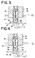
- a liquid inlet port open-to-close valve 34 is installed in the tank 25 to open or close the liquid inlet port 29 of the suction nozzle 28. Further, a float 35 with large buoyancy and floating on the drain surface in the tank 25 is placed in the tank 25. The liquid inlet port open-to-close valve 34 and the float 35 are connected with a connecting shaft 36 which has a cushioning effect in the vertical direction.
- the float 35 tends to move upwards.
- the liquid inlet port open-to-close valve 34 also tends to move upwards, pulled by the float 35.
- the rising force of the liquid inlet port open-to-close valve 34 based on the buoyancy of the float 35 exceeded the suction force of the suction nozzle 28 by the evacuating effect of the first tank 3
- the liquid inlet port open-to-close valve 34 moves upwards, lifting from the liquid inlet port 29 so that the liquid inlet port 29 is released (see Fig. 4).
- drain is sucked from the opened liquid inlet port 29 so that the drain level in the tank 25 is lowered and the float 35 moves downwards.
- the liquid inlet port open-to-close valve 34 moves downward accordingly, and the liquid inlet port open-to-close valve 34 sticks to the liquid inlet port 29 by both the self-weight thereof and suction effect from the liquid inlet port 29, and the liquid inlet port 29 is closed. Since the weight of the float 35 is added to the liquid inlet port open-to-close valve 34 as the drain level lowers further, tightness between the liquid inlet port open-to-close valve 34 and the liquid inlet port 29 increases and no more drain is sucked through the suction nozzle 28 (see Fig. 3).
- the liquid inlet port 29 of the suction nozzle 28 is made of soft material having water resistance and durability so as to be tightly closed by sticking to the liquid inlet port open-to-close valve 34, thereby to keep a tightness between the liquid inlet port 29 and the liquid inlet port open-to-close valve 34.
- One material suitable for this purpose is silicone rubber, for example.
- the bottom surface, at least, of the liquid inlet port open-to-close valve 34 must be smooth so as to stick to the liquid inlet port 29 of the suction nozzle 28.
- the bottom surface of the liquid inlet port open-to-close valve 34 need not necessarily be flat, but can be e.g. spherical as long as it can stick to and seal the liquid inlet port 29.
- the float 35 and the liquid inlet port open-to-close valve 34 may be formed in one body and a part of the float 35 can be used instead of the liquid inlet port open-to-close valve 34 to provide similar effect.
- the liquid inlet port open-to-close valve 34 Since the liquid inlet port open-to-close valve 34 is released from the liquid inlet port 29 according to rising up of the float 35 and sticks to the liquid inlet port 29 according to lowering of the float 35, it must be placed right above the liquid inlet port 29 in this embodiment. That is, the liquid inlet port open-to-close valve 34 should not move in a horizontal direction significantly after lifting upwards from the liquid inlet port 29 according to rising up of the float 35 caused by rising up of the drain level in the tank 25.
- a guide cylinder 37 having enough inner space for the vertical movement of the liquid inlet port open-to-close valve 34 is provided in the tank 25.
- the guide cylinder 37 acts as a guide member to restrict the moving direction of the liquid inlet port open-to-close valve 34 which moves according to upward and downward movement of the float 35.
- the cylinder 37 is provided with perforations 38 on the surrounding wall thereof to allow free passage of drain.
- the perforations 38 are placed on the lower part of the cylinder 37.
- the cylinder 37 can be made of meshed material. When material having fine mesh is used, it may also have an effect as a strainer to remove dusts contained in drain. According to the embodiment shown in Figs. 2, 3 and 4, the cylinder 37 is extended far upward to guide the vertical movement of the float 35 and is inserted into a cylindrical hole 39 which is formed upwards from the bottom center of the float 35.
- liquid inlet port open-to-close valve 34 and the float 35 are allowed to move vertically to open the liquid inlet port 29 or to close the liquid inlet port 29 under restriction by the guide cylinder 37 according to rising up or lowering down of the drain level in the tank 25.
- An overflow detecting sensor 40 is attached at a suitable position of the tank 25 to be actuated when the drain level in the tank 25 exceeds a predetermined limit by any chance.
- the overflow detecting sensor 40 is interlinked with the air-conditioner 7 so that the air-conditioner 7 is stopped and an alarm gives a warning signal when the drain level in the tank 25 has risen abnormally by any chance.
- Numeral 41 in Fig. 2 show filters to prevent dusts contained in the drain from being sucked into the drain suction pipe 31.
- the filters 41 are constructed to be easily taken out by removing a lid 42 covering the top of the tank 25 so as to simplify the performance of maintenance.
- drain produced by the air-conditioner 7 mounted in ceiling plenum of each floor or room continuously flows down by natural gravity into the tank 25 provided nearby the air-conditioner 7 and is collected therein.
- drain in the tank 25 is sucked into the first tank 3 through the suction nozzle 28, the drain suction pipe 31, the branch pipe 2 and the drain recovery main pipe 1.
- the float 35 moves downwards. Then, the liquid inlet port open-to-close valve 34 moves downwards along the guide cylinder 37 and approaches the liquid inlet port 29. Since the liquid inlet port 29 of the suction nozzle 28 continues to suck up drain, the liquid inlet port open-to-close valve 34 is pulled to the liquid inlet port 29 by such suction force. As a result, the liquid inlet port 29 is closed so that the drain suction is interrupted on one hand and the inside of the first tank 3 is kept at reduced pressure on the other hand.
- Drain is flowing continuously into the tank 25 as the air-conditioner 7 is still being operated.
- the float 35 moves upwards according to rising up of the drain level by the inflow of drain into the tank 25.
- the liquid inlet port open-to-close valve 34 is pulled upwards by the float 35 and finally released from the liquid inlet port 29 when a buoyancy higher than suction force of the suction nozzle 28 acts upon the liquid inlet port open-to-close valve 34.
- the liquid inlet port 29 of the suction nozzle 28 is opened and sucks up drain as aforementioned.
- drain suction pipe 31 is constructed of a small diameter flexible pipe as described above, there is no plugging problem of the drain pipe 31 because drain is sucked up by the suction force of the first tank 3 under reduced pressure.
- the first tank 3 and the second tank 11 are connected by the connection pipe 10 to transfer drain from former to latter and also by the bypass pipe 13 to equalize each internal pressure in both tanks 3 and 11.
- the main valve 12 and the bypass valve 14 installed in the pipes 10 and 13, respectively, are normally opened. Therefore, the internal pressure in the second tank 11 and that in the first tank 3 is equal to each other so that drain flows smoothly from the first tank 3 to the second tank 11.
- the float switch 18 attached to the second tank 11 is actuated to cause closing action of the main valve 12 and the bypass valve 14, followed by open action of the vent valve 15 and the discharge valve 17. Consequently, drain retained in the second tank 11 is discharged to the outside of the apparatus.
- the float switch 18 When discharge of collected drain is completed, the float switch 18 is actuated again to close the vent valve 15 and the discharge valve 17, followed by opening of the main valve 12 and the bypass valve 14.
- the valves 12 and 14 When the valves 12 and 14 are opened, the internal pressure in the first tank 3 is equalized to that in the second tank 11.
- a pressure switch 9 is provided in the first tank 3 so as to operate the vacuum pump 5 according to change of the internal tank pressure and to keep the internal tank pressure constant, the internal pressure each in the first and second tanks 3, 11 returns to the specified degree of vacuum immediately.
- drain produced from plural of the air-conditioners 7 is discharged to the outside continuously, safely and surely.
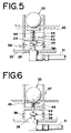
- Figs. 5 and 6 show a second embodiment of said terminal unit B.
- a liquid inlet port open-to-close valve 34 is always biased so as to release a liquid inlet port 29.
- an introrse flange 43 is provided in a guide cylinder 37 at a position above the liquid inlet port 29, a frame member 44 is provided so as to pierce vertically the middle part of this flange 43 with some clearance, a float receiver 45 is provided on the top of the frame member 44 while said liquid inlet port open-to-close valve 34 is provided on the lower end thereof, further a compression coil spring 46 is provided on the frame member 44 between the bottom surface of the float receiver 45 and the upper surface of the flange 43.
- This compression coil spring 46 has a sufficiently stronger spring power than the suction force of a suction nozzle 28 that the spring is only compressed when the weight of the float is added to the suction force.
- the guide cylinder 37 must control not only the path of movement of the liquid inlet port open-to-close valve 34, but also movement of the float 35. In this embodiment, unlike said first embodiment, this is required because the float 35 and the liquid inlet port open-to-close valve 34 are separate and not connected to each other.
- the float 35 moves upwards from the float receiver 45 according to rising of the drain level in a tank 25.
- the float receiver 45 is pushed upwards by action of the compression coil spring 46 and the liquid inlet port open-to-close valve 34 also moves upwards accordingly, so that the liquid inlet port is opened (refer to Fig. 5).
- Fig. 7 shows a third embodiment.
- This embodiment relates to a guide member including other parts made in accordance with the present invention.
- a float 35 is connected with the end part 47a of an arm 47 extending almost horizontally while another basal end part 47b of the arm 47 is attached at almost the same level as the drain level so as to be freely rotatable.
- the basal end part 47b of the arm 47 is pivoted, with a horizontal pivot axis 49, on the upper end of a column member 48 which is installed and erected on the internal bottom surface of the tank 25 in the embodiment shown in the drawing.
- the present invention is not restricted to this embodiment, and according to another embodiment said end part 47b of the base of the arm 47 can be directly pivoted on the internal side of the tank 25.
- a liquid inlet port open-to-close valve 34 is connected, through a means having elasticity in upward and downward directions, to an appropriate position near to the base part of the arm 47.
- a compression coil spring 50 is provided as an example of such an elastic means.
- the system is so configured that the arm 47 is able to rotate round the horizontal pivot axis 49 of the end part 47b of the base of the arm 47 whenever said float 35 is caused to move in the upward and downward directions according to changes of the drain level.
- this movement causes, through a movement of the compression coil spring 50, a liquid inlet port open-to-close valve 34 to be moved downward and upward, thereby a liquid inlet port 29 is opened or closed.
- the end part 47a of the arm 47 simply moves up and down about the horizontal pivot axis 49 and never moves horizontally, thus causing the liquid inlet port open-to-close valve 34 to move in a direction approaching or leaving said liquid inlet port 29, thereby achieving a regular and precise action of said liquid inlet port open-to-close valve 34. That is, according to the third embodiment the arm 47 being pivoted by the horizontal pivot axis 49 acts as a guide member to regulate the directional movement of said liquid inlet port open-to-close valve 34.
- the compression coil spring 50 used as an elastic means is not necessarily required, when the arm 47 is connected with said liquid inlet port open-to-close valve 34 using such elastic means, it can provide a cushioning effect on the opening and closing operations of the liquid inlet port open-to-close valve 34 according to the vertical movement of said float 35.
- Fig. 8 shows a fourth embodiment, wherein a suction nozzle 28 is attached in a different way, resulting in a change of operational direction of said liquid inlet port open-to-close valve 34.
- said suction nozzle 28 is attached so as to pierce horizontally through the lower side wall of said tank 25, that is, said liquid inlet port 29 is accordingly positioned laterally.
- an end part 51a of an L-shaped arm 51 To the float 35 floating on the surface of drain is connected an end part 51a of an L-shaped arm 51.
- the arm 51 extends horizontally and another basal end part 51b thereof is bent downward.
- the vertical part 52 of the arm 51 is pivoted almost half way therealong with a horizontal pivot axis 53.
- a bracket 54 is provided so as to protrude horizontally from the internal wall of the tank 25 and the vertical part 52 of the arm 51 is attached half way along to this bracket 54 through the horizontal pivot axis 53.
- the liquid inlet port open-to-close valve 34 is fixed directly or indirectly on the lower end 52a of the vertical part 52 of the arm 51.
- the liquid inlet port open-to-close valve 34 is positioned near to and facing towards the liquid inlet port 29 of the suction nozzle 28.
- the lower end 52a of the vertical part 52 of the arm 51 is also moved simultaneously as if it traces a partial circular arc and such movement of the lower end 52a causes the liquid inlet port open-to-close valve 34 to be moved in a direction approaching or leaving the liquid inlet port 29, thereby the liquid inlet port 29 of the suction nozzle 28 can be opened or closed.
- the movement direction of the liquid inlet port open-to-close valve 34 is controlled and regulated by the arm 51 as a guide member pivoted by the horizontal pivot axis 53, so that a regular and precise movement of the liquid inlet port open-to-close valve 34 in the direction approaching or leaving the liquid inlet port 29 of the suction nozzle 28 can be controlled.
- the apparatus can easily be installed in the ceiling space, providing a sufficient difference of elevation between the tank 25 and air conditioner 7.
- Fig. 9 shows a fifth embodiment, wherein the suction nozzle 28 is installed so as to point downward in the tank 25.
- a bracket 55 is attached to the lower surface of an upper cover 42 of the tank 25 and the suction nozzle 28 is supported by the bracket 55.
- a drain suction tube 31 attached to the suction nozzle 28 passes through the upper cover 42 of the tank 25.
- the position of the suction nozzle 28 can be easily adjusted in the upward and downward directions. That is, the suction nozzle 28 also passes vertically through the horizontal part 55a of the bracket 55.
- the horizontal part 55a of the bracket 55 is sandwiched between two position adjusting nuts 56 having a female screw to engage with a male screw formed around the suction nozzle 28. Therefore, the upward and downward position of the suction nozzle 28 can be adjusted by rotating each nut 56, thereby permitting free adjustment of the level of the liquid inlet port 29 of the suction nozzle 28.
- the suction nozzle 28 is equipped with a check valve 33 and a strainer (not shown in the drawing).
- the end part 57a of the arm 57 is connected to the float 35 floating on the surface of drain in the tank 25.
- This arm 57 is pivoted by a horizonal pivot axis 58 at almost the mid point thereof.
- Another end part 57b of the arm 57 is positioned at a level lower than the drain surface and the upper surface of the end part 57b is provided with the liquid inlet port open-to-close valve 34.
- This liquid inlet port open-to-close valve 34 is positioned at a level lower than the liquid inlet port 29 of the suction nozzle 28.
- the upper and lower positions of the arm 57 can be freely adjusted. That is, the horizontal pivot axis 58 is supported by the lower end of a bar member 59 positioned vertically.
- the bar member 59 passes vertically through the horizontal part 55a of the bracket 55.
- the horizontal part 55a of the bracket 55 is sandwiched between two position adjusting nuts 60 having a female screw to engage with a male screw formed around the bar member 59 and, therefore, by rotating each nut 60, the upper and lower positions of the am 57 can be freely adjusted.
- the end 57b of the arm 57 can move upward and downward taking a position of the horizonal pivot axis 58 as a center of the movement.
- This causes the liquid inlet port open-to-close valve 34 to move in a direction towards or away from the liquid inlet port 29, thereby the liquid inlet port 29 of the suction nozzle 28 can be opened or closed.
- the movement of the liquid inlet port open-to-close valve 34 is controlled and regulated by the arm 57 as a guide member pivoted about the horizontal pivot axis 58, thus always providing a regular and precise movement of the liquid inlet port open-to-close valve 34 in a direction towards or away from the liquid inlet port 29 of the suction nozzle 28.
- the apparatus can be easily assembled because the suction nozzle 28 can be installed from the upper side of the tank 25.
- the apparatus according to the fifth embodiment unlike those in embodiments 1 to 3, there are no protruded objects such as pipes on the under-surface of the bottom 25a of the tank 25, thus the apparatus can be easily installed in the ceiling space permitting a sufficient difference of elevation between the tank 25 and air conditioner 7. Furthermore, by adjusting the upper and lower positions of both the suction nozzle 28 and the arm 57, the upper limit of drain level in the tank 25 can be easily changed, if necessary.
- Said terminal unit B may alternatively be generally constructed as follows; instead of the liquid inlet port open-to-close valve 34 and the float 35, a float switch can be installed to detect the drain level in the receiving tank 25. Also an electromagnetic valve can be installed to close or open the drain suction pipe 31 using signals emitted from said float switch.
- a float switch can be installed to detect the drain level in the receiving tank 25.
- an electromagnetic valve can be installed to close or open the drain suction pipe 31 using signals emitted from said float switch.
- the apparatus according to the first to fifth embodiments do not use electronic materials such as a float switch or electromagnetic valve, thus a simple system configuration can be realized which can be supplied with lower cost, and does not require any wiring processes, thus enabling easy installation of the system. It also can minimize malfunction and accordingly ensures reliable operation.
- the automatic draining apparatus described in the first to fifth embodiments are particularly suitable for systematically collecting drain discharged from air conditioners of a building equipped with many air conditioners (for example, more than 20 units). In some cases, however, these apparatus may be costly if applied to a building equipped with fewer air conditioners (for example, less than 20) because installation of said vacuum tank body A may require large-scale construction work and require very high initial investment.
- Figs. 10 and 11 illustrate embodiments of the automatic draining apparatus which can be driven and activated based on operational principles totally different from those adopted in the apparatuses shown in the first to fifth embodiments, thereby successfully performing the same purpose as already explained above.
- the automatic draining apparatus described below is particularly suited, thanks to its low initial cost, for systematically collecting drain in a building equipped with small numbers of air conditioners.
- Fig. 10 is a fluid circuit diagram of the automatic draining apparatus according to a sixth embodiment, wherein the automatic draining apparatus is housed in a storage box 61 shown by broken lines in the drawing, constituting a draining system C.
- the draining system C is installed, as liquid discharging equipment, for example, adjacent to an air conditioner 7. If the air conditioner has a space enough to contain the system, this system can be installed within that space.
- the automatic draining apparatus is equipped with a sealed tank 63.
- the internal space of the tank 63 is connected and communicated, through a liquid flow path 64, to a drain discharge outlet 84 of the air conditioner 7.
- the draining system C is so installed that the tank 63 is positioned at a level lower than the drain discharge outlet 84 of the air conditioner 7. As the result, by natural gravity, drain discharged from the air conditioner 7 flows into the tank through the liquid flow path 64.
- a liquid flow path open-to-close valve 65 consisting of an electrically operated valve or an electromagnetic valve.
- the drain discharging outlet 84 of the air conditioner 7 is freely connected or disconnected with the internal space of the tank 63 optionally by on-off actions of the liquid flow path open-to-close valve 65.
- the tank 63 is equipped with a float switch 66 as a drain level detecting means to detect the upper L3 and the lower L4 limits of the drain level in the tank 63.
- the upper L3 and the lower L4 limits of the drain level in the tank 63 can be predetermined appropriately.
- the float switch 66 is automatically activated.
- float switch 66 The precise construction of the float switch 66 will not be described in detail. Any suitable type of switch including a floating type or known electrode-type (electrode bar type) of switch is acceptable.
- a drain outlet passage hereinafter referred to as a "drain piping line” 67, which is used to forcedly discharge drain collected in the tank 63, is attached to the tank 63.
- the internal opening 67a of the drain piping 67 is positioned at a level lower than the lower limit level L4 of the drain surface in the tank 63.
- the drain piping 67 passes through the upper side 63a of the tank 63, keeping air tightness, and extends towards the outside thereof.
- the drain piping open-to-close valve 68 composed of an electrically operated or electromagnetic valve is attached to an appropriate position of the drain piping 67 protruding outside from the tank 67.
- the drain piping open-to-close valve 68 can prevent flow back of drain exhausted through the drain piping 67.
- a manual valve (not shown in the drawing) is attached to an appropriate position half way along the drain piping 67 outside of the storing box 61 for convenience of maintenance.
- a check valve 69 which can function as a switch to be activated by flowing pressure of drain, can be used, or combined use of the draining piping open-to-close valve 68 and the check valve 69 is possible as shown in the illustrated embodiment.
- the check valve 69 acts as a safety valve to be used if the drain piping open-to-close valve 68 fails to operate due to malfunction.
- An air compressor 70 as an air supply source is connected, through an air flow path 71, to the tank 63.
- the air flow path 71 passes, keeping air tightness, through the tank 63, and is opened at a level higher than the upper limit of the drain surface L3.
- the air flow path 71 is used to feed air into the tank 63 which can raise internal pressure of the tank 63 and to discharge drain forcedly from the drain piping 67.
- the end opening part 71a of the air flow path 71 can be dipped into drain in the tank 63.
- it is desirable that the air flow path 71 is opened at a level higher than the upper limit L3 of drain as shown in Fig. 10.
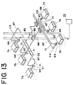
- any suitable type of air compressor 70 to be used as an air supply source is acceptable. If, however, many drain systems C (C1 to C6) are activated by one air compressor 70 alone as shown in Fig. 13, it is necessary to select an air compressor 70 having enough capacity taking the number of drain systems in consideration.
- An air flow path open-to-close valve 72 comprising an electrically operated or electromagnetic valve is attached to an appropriate position of the air flow path 71.
- the on-off of air flow into the tank 63 is optionally controlled by opening and closing operations of the air flow path open-to-close valve 72.
- vent piping 73 which is used to achieve communication between the outside and inside of the tank 63, is attached to the tank 63.
- the purpose of the vent piping 73 is to lower the internal pressure in the tank 63, which has been already raised by the supply of air at the time of forced discharging of drain, down to an air pressure level after drain has been discharged and also to keep the internal pressure in the tank 63 at ambient air pressure by having the outside and inside of the tank 63 communicated when drain flows from the air conditioner 7 into the tank 63.
- the vent piping 73 is used also as the air flow path 71 and its internal opening part 73a is installed at a level higher than the upper limit L3 of the drain level in the tank 63.
- the vent piping 73 passes through the upper side 63 of the tank 63, keeping air tightness, and extends upward and then outside thereof.
- a vent piping open-to-close valve 74 comprising an electrically operated or electromagnetic valve is attached to an appropriate position of the vent piping 73 extending outwardly from the tank 63.
- the on-off operation of the vent piping open-to-close valve 74 controls the start and stop of the communication between the outside and inside of the tank 63.
- a silencer 75 it is preferable to attach a silencer 75 to the external end 73a of the vent piping 73 with the aim of preventing noise during discharging.
- electromagnetic valves in order to minimize such noise, for the liquid flow path open-to-close valve 65, drain piping open-to-close valve 68, air flow path open-to-close valve 72 and vent piping open-to-close valve 74 respectively, a DC driving-type valve is recommended because it is designed to minimize operational noise.
- a pressure gauge (not shown in the drawing) can be mounted on the tank 63 in order to observe changes in pressure in the tank 63.
- numeral 76 is a strainer provided on the liquid flow path 64 upstream of the liquid flow path open-to-close valve 65.
- the strainer 76 is used to remove dust and the like contained in drain before drain flows into the tank 63.
- Numeral 77 is a filter which is provided around the internal opening 67a of the drain piping 67.
- the filter 77 is used to prevent dust and the like in the tank 63 from entering the drain piping 67 during forced discharging.
- the filter 77 in the tank 63 is not necessarily required, however, instalment of both of them is more preferable.
- Numeral 78 is an overflow detecting sensor which is activated when the level of drain in the tank 63 exceeds the limit quantity due to malfunction of the float switch 66.
- the overflow detecting sensor 78 is interlocked with the air conditioner 7 which is activated, if the drain level in the tank 63 is raised abnormally, to stop operation of the air conditioner 7 and to sound an alarm.
- Numeral 79 is a air duct open-to-close valve and numeral 80 is a pressure regulating valve for maintenance provided on the air path 71 upstream of the air duct open-to-close valve 72.
- the air duct open-to-close valve 79 for maintenance is used, for example, to perform maintenance on the air duct open-to-close valve 72, wherein it is used to temporarily stop the air supply on the upstream side of the air duct open-to-close valve 72.
- the air duct open-to-close valve 79 for maintenance use can be installed either outside or inside of the drain system C.
- the pressure regulating valve 80 is used to control pressure of air to be fed into the tank 63 whenever necessary and is built in each drain system C.
- the float switch 66 When drain from the air conditioner 7 continues to flow into the tank 63, the float switch 66 then detects the upper limit L3 of the drain level in the tank 63. When the vent piping open-to-close valve 74 and liquid flow path open-to-close valve 65 receive the signal for the upper limit L3, both of valves, which had been opened, are automatically closed, thereby temporarily stopping communication between the air conditioner 7 and the tank 63 and, as a result, the tank 63 is internally and completely sealed.
- the air duct open-to-close valve 72 and the drain piping open-to-close valve 68 which had been closed, are automatically opened, thereby allowing air for forced draining to flow into the sealed tank 63 and the internal pressure of the tank 63 to be raised and, as a result, drain is forcedly discharged through the drain piping 67.
- the float switch 66 detects the lower limit L4.
- the vent piping open-to-close valve 74 and the liquid flow path open-to-close valve 65 are automatically opened and, as a result, the internal pressure in the tank 63 returns to normal pressure and the communication between the air conditioner 7 and the tank 63 is restored.
- the opening and closing valves are so controlled that the liquid flow path open-to-close valve 65 cannot be opened until the vent piping open-to-close valve 74 is opened completely.
- Fig. 11 shows a flow circuit diagram related to a seventh embodiment.
- the automatic draining apparatus shown in the seventh embodiment has, for the most part, the same configuration as that shown in the sixth embodiment.
- the system configuration and operations clearly being different from those of the automatic draining apparatus shown in sixth embodiment will be described in detail and if materials or components are the same as shown in the sixth embodiment, the same characters or numerals are used and overlapping descriptions are omitted.
- a three-way valve 91 is introduced wherein selective connection of the internal side of the tank 63 with either the air supply source 70 or the outside of the tank 63 becomes possible.
- a common piping 90 is formed combining the air duct 71 and the vent piping 73.
- the common piping 90 passes through the upper part 63a of the tank 63, keeping air tightness.
- the internal opening part 90a of the common piping 90 is installed at a level higher than the drain limit L3 in the tank 63.
- the three-way valve 91 composed of an electrically operated or an electromagnetic valve is installed. The three-way valve 91 is used to selectively and alternatively connect either of the air duct 71 or the vent piping 73 with the common piping 90.
- the three-way valve 91 is automatically controlled so as to perform linked operations with the float switch 66 together with the liquid flow path open-to-close valve 65 and the drain piping open-to-close valve 68.
- the following is mechanism of the control.
- the float switch detects the upper limit L3 of the drain level in the tank 63.
- the valve 65 which had been opened, is automatically closed, thereby temporarily stopping communication between the air conditioner 7 and the tank 63.
- the connection of the common piping 90 with the vent piping 73 is automatically switched by the three-way valve 91 over to another connection of the common piping 90 with the air flow path 71 and the drain piping open-to-close valve 68 is automatically opened.
- the air to be used for forced draining is allowed to flow into the sealed tank 63 and the internal pressure of the tank 63 to be raised, thus performing forced discharge of drain through the drain piping 67.
- the float switch 66 detects the lower limit L4.
- the connection of the common piping 90 with the air duct 71 is automatically switched by the three-way valve 91 over to another connection of the common piping 90 with the vent piping 73 and the drain piping open-to-close valve 68 is automatically closed. This causes forced discharging operation of drain to be stopped and the internal pressure, which had been raised, in the tank 63 returns to atmospheric pressure.
- the liquid flow path open-to-close valve 65 is automatically opened accordingly. This restores the communication between the air conditioner 7 and the tank 63 thereby restarting the inflow of drain from the air conditioner 7. By repeating said operations, drain from the air conditioner 7 is surely discharged outside of the tank 63.
- the automatic draining apparatus in the embodiment shown in Fig. 11 has the following advantages over that in the embodiment shown in Fig. 10.
- the opening time of the vent piping open-to-close valve 74 is much longer than the closing time.
- the vent piping open-to-close valve 74 remains opened while drain is flowing from the air conditioner 7 into the tank 63 (its flowing-in time is longer in general) and it is closed only when drain is forcedly discharged (its flowing-out time is shorter in general).
- the type of electromagnetic valve called “Close On Power”, which remains closed while power is on, is preferable as the vent piping open-to-close valve 74.
- the reason is that, if the type of electromagnetic valve called “Open On Power”, which is designed to be opened while power is on, is used, its life is made shorter due to longer passage time of the electric current.
- valves of "Open On Power” type are valves of "Open On Power” type.
- valves of such "Close On Power” type currently available variety is very limited and they are very expensive.
- vent piping open-to-close valve 74 nor the air duct open-to-close valve 72 are used in the embodiment of Fig. 11 and, instead of these, a three-way valve 91 is introduced. This can provide advantages such as simplicity in its configuration and reduction in costs.
- the automatic draining apparatus shown in the sixth and seventh embodiments designed to discharge drain continuously or intermittently, is most suitable for use in places where drain cannot be discharged by natural gravity such as a fresh food showcase 81 in which the air conditioner 7 or a humidifying device is built.
- Fig. 12 shows an alternative application of the automatic draining apparatus described in the sixth and seventh embodiments, wherein the apparatus is used to discharge drain from an air conditioner 7 installed in a ceiling space 82, i.e., the draining system C containing the automatic draining apparatus is installed adjacent to the air conditioner 7 and the drain piping 67 and the air duct 71 are set in a place free from an obstructed object 83 in the ceiling space 82.
- drain piping 67 and the duct 71 are made of flexible tubes of as comparatively small such as 6 mm or so in internal diameter, its installation in such narrow space is possible, which can make the construction time for the system shorter and saving material and labor costs. Because the fluid is conveyed by pressure in both the drain piping 67 and the air duct 71, there is no fear of being blocked even though such flexible tube with a smaller diameter is used.
- a drain recovery main pipe 85 and an air supply main duct 86 are connected with a drain recovery main pipe 85 and an air supply main duct 86.
- Each air compressor 70 is attached to the air supply main duct 86.
- the numeral 92 in Fig. 13 is a pressure gauge used to check the pressure of air which is conveyed by pressure to the drain system C through the air supply main duct 86 from the air compressor 70.
- Fig. 14 shows another application of the draining system used to collect drain discharged from a fresh food showcase 81 (81a and 81b) in which the humidifying device is built.
- such showcase 81 from which drain is discharged, is laid with its back turned against the wall 87 (as shown as by 81a) at selling places in supermarkets or department stores or laid at the center of stores (as shown as by 81b).
- the installation required to collect drain is very difficult.
- the drain piping 67 and the air duct 71 can be installed upward to the ceiling wherein they are connected to the preliminarily installed drain recovery main piping 85 and the air supply main duct 86, thereby permitting satisfactory collection of drain, easy installation and good appearance.
- the lay-out of such showcases is often changed due to sales promotion strategy in stores, however, if the drain recovery main piping 85 and the air supply main duct 86 are installed in advance in the ceiling space and a plurality of connections 87 and 88 are built in them, the drain piping 67 and the air duct 71 can be freely connected, thereby enabling easy discharging of drain from the showcase regardless of positions of the showcase 81 within the store, thereby eliminating any restriction in lay-out of the showcase 81 as well.
- an automatic draining apparatus capable of discharging drain safely and surely, regardless of the installation position of the liquid source; and there is provided an automatic drain system capable of systematically collecting drain from multiple liquid sources; and there is provided an automatic draining system capable of allowing the installation position of the liquid source(s) to be freely changed; and there is provided an automatic draining apparatus or an automatic draining system capable of allowing simple installation of the drain pipe.
Landscapes
- Engineering & Computer Science (AREA)
- Chemical & Material Sciences (AREA)
- Combustion & Propulsion (AREA)
- Mechanical Engineering (AREA)
- General Engineering & Computer Science (AREA)
- Physics & Mathematics (AREA)
- Thermal Sciences (AREA)
- Devices For Blowing Cold Air, Devices For Blowing Warm Air, And Means For Preventing Water Condensation In Air Conditioning Units (AREA)
- Feeding, Discharge, Calcimining, Fusing, And Gas-Generation Devices (AREA)
- Control Of Non-Electrical Variables (AREA)
Applications Claiming Priority (4)
| Application Number | Priority Date | Filing Date | Title |
|---|---|---|---|
| JP227354/94 | 1994-08-29 | ||
| JP22735494 | 1994-08-29 | ||
| JP6282629A JPH08121806A (ja) | 1994-08-29 | 1994-10-21 | 自動排液装置及び同装置を用いた自動排液システム |
| JP282629/94 | 1994-10-21 |
Publications (2)
| Publication Number | Publication Date |
|---|---|
| EP0699877A2 true EP0699877A2 (de) | 1996-03-06 |
| EP0699877A3 EP0699877A3 (de) | 1996-12-04 |
Family
ID=26527629
Family Applications (1)
| Application Number | Title | Priority Date | Filing Date |
|---|---|---|---|
| EP95303128A Withdrawn EP0699877A3 (de) | 1994-08-29 | 1995-05-09 | Automatisches Entwässerungsgerät und dieses verwendende automatische Entwässerungsanlage |
Country Status (4)
| Country | Link |
|---|---|
| EP (1) | EP0699877A3 (de) |
| JP (1) | JPH08121806A (de) |
| KR (1) | KR960007439A (de) |
| GB (1) | GB2292803A (de) |
Cited By (20)
| Publication number | Priority date | Publication date | Assignee | Title |
|---|---|---|---|---|
| SG85186A1 (en) * | 2000-05-29 | 2001-12-19 | Zhong Qian Zhao | Air conditioning condensate drainage |
| SG92794A1 (en) * | 2001-04-20 | 2002-11-19 | Yang Kun Tin | Noiseless water draining device of air conditioner |
| EP1172491A3 (de) * | 2000-07-11 | 2003-01-02 | Evac International Oy | Apparat zur Schaumableitung für einen Vakuumsammelbehälter |
| ES2223303A1 (es) * | 2003-08-14 | 2005-02-16 | Bsh Electrodomesticos España S.A. | Equipo de climatizacion. |
| WO2007075015A3 (en) * | 2005-12-26 | 2009-05-22 | Wan Young Lee | Automatic draining apparatus of condensation |
| EP1910755A4 (de) * | 2005-07-29 | 2011-10-26 | Carrier Corp | Kondensatablaufschlauchanordnung für eine verdampfereinheit |
| US8802189B1 (en) | 2010-08-03 | 2014-08-12 | Cubic Tech Corporation | System and method for the transfer of color and other physical properties to laminate composite materials and other articles |
| CN104089391A (zh) * | 2014-07-18 | 2014-10-08 | 江苏友奥电器有限公司 | 一种洒水机构 |
| US9114570B2 (en) | 2012-11-09 | 2015-08-25 | Cubic Tech Corporation | Systems and method for producing three-dimensional articles from flexible composite materials |
| US9154593B1 (en) | 2012-06-20 | 2015-10-06 | Cubic Tech Corporation | Flotation and related integrations to extend the use of electronic systems |
| US9358755B2 (en) | 2010-06-24 | 2016-06-07 | Cubic Tech Corporation | Waterproof breathable composite materials for fabrication of flexible membranes and other articles |
| CN105952007A (zh) * | 2016-06-27 | 2016-09-21 | 中铁十九局集团电务工程有限公司 | 一种通风管道自动排水装置 |
| US9789662B2 (en) | 2013-03-13 | 2017-10-17 | Cubic Tech Corporation | Engineered composite systems |
| US10189209B2 (en) | 2013-03-13 | 2019-01-29 | Dsm Ip Assets B.V. | Systems and method for producing three-dimensional articles from flexible composite materials |
| US10513088B2 (en) | 2015-01-09 | 2019-12-24 | Dsm Ip Assets B.V. | Lightweight laminates and plate-carrier vests and other articles of manufacture therefrom |
| CN112965539A (zh) * | 2021-02-24 | 2021-06-15 | 徐逸萍 | 一种用于数控机床的机油箱液位保持装置 |
| US11072143B2 (en) | 2013-03-13 | 2021-07-27 | Dsm Ip Assets B.V | Flexible composite systems and methods |
| CN114084355A (zh) * | 2021-11-22 | 2022-02-25 | 中国商用飞机有限责任公司 | 高压水分离器及其控制方法、存储介质 |
| CN114278720A (zh) * | 2021-12-30 | 2022-04-05 | 重庆长安汽车股份有限公司 | 一种可防水的汽车减速器系统 |
| CN114899898A (zh) * | 2022-04-15 | 2022-08-12 | 上海智租物联科技有限公司 | 一种水浸式灭火换电充电柜系统及其灭火方法 |
Families Citing this family (4)
| Publication number | Priority date | Publication date | Assignee | Title |
|---|---|---|---|---|
| ZA200807345B (en) * | 2007-08-30 | 2015-11-25 | Exol Group (Pty) Ltd | Movable storage tank, movable storage tank with draining apparatus and draining apparatus |
| KR101405921B1 (ko) * | 2013-10-25 | 2014-06-17 | 주식회사 세종엠이씨 | 공기조화기용 응축수 배출장치 |
| JP6663205B2 (ja) * | 2015-11-12 | 2020-03-11 | ユーキャン株式会社 | 自動排液装置及び排液方法 |
| CN108088156B (zh) * | 2017-12-01 | 2021-10-29 | 海尔智家股份有限公司 | 化霜排水组件及具有其的冰箱 |
Family Cites Families (12)
| Publication number | Priority date | Publication date | Assignee | Title |
|---|---|---|---|---|
| GB744453A (en) * | 1952-12-15 | 1956-02-08 | Kracht Pumpen Motoren | Automatic air volume control for a liquid supply system |
| GB1204127A (en) * | 1967-02-01 | 1970-09-03 | Blaw Knox Ltd | Improvements in or relating to arrangements for priming centrifugal pumps |
| SE358542B (de) * | 1971-12-10 | 1973-08-06 | Alfa Laval Ab | |
| JPS58158435A (ja) * | 1982-03-15 | 1983-09-20 | Matsushita Electric Ind Co Ltd | 除湿機の満水停止装置 |
| US4633673A (en) * | 1984-09-14 | 1987-01-06 | Morrison Daniel R | Emergency shutoff for air conditioners |
| US5042518A (en) * | 1990-10-25 | 1991-08-27 | Singhe Upenda W | Liquid elimination system for vacuum line |
| US5085244A (en) * | 1991-03-14 | 1992-02-04 | Funk Douglas H | Assembly for cleaning a drain conduit |
| JP3117241B2 (ja) * | 1991-04-26 | 2000-12-11 | 東芝キヤリア株式会社 | 空気調和機 |
| US5271237A (en) * | 1992-12-10 | 1993-12-21 | Electric Power Research Institute, Inc. | Apparatus for condensate removal |
| JPH06174147A (ja) * | 1992-12-14 | 1994-06-24 | Ebara Corp | 真空弁 |
| US5285653A (en) * | 1992-12-30 | 1994-02-15 | Carrier Corporation | Refrigerant flow control device |
| US5293894A (en) * | 1993-02-11 | 1994-03-15 | Fleischmann Lewis W | Automatic prime and flush siphon condensate pump system |
-
1994
- 1994-10-21 JP JP6282629A patent/JPH08121806A/ja active Pending
-
1995
- 1995-03-27 GB GB9506235A patent/GB2292803A/en not_active Withdrawn
- 1995-05-09 EP EP95303128A patent/EP0699877A3/de not_active Withdrawn
- 1995-08-23 KR KR1019950026205A patent/KR960007439A/ko not_active Withdrawn
Cited By (25)
| Publication number | Priority date | Publication date | Assignee | Title |
|---|---|---|---|---|
| SG85186A1 (en) * | 2000-05-29 | 2001-12-19 | Zhong Qian Zhao | Air conditioning condensate drainage |
| EP1172491A3 (de) * | 2000-07-11 | 2003-01-02 | Evac International Oy | Apparat zur Schaumableitung für einen Vakuumsammelbehälter |
| SG92794A1 (en) * | 2001-04-20 | 2002-11-19 | Yang Kun Tin | Noiseless water draining device of air conditioner |
| ES2223303A1 (es) * | 2003-08-14 | 2005-02-16 | Bsh Electrodomesticos España S.A. | Equipo de climatizacion. |
| EP1910755A4 (de) * | 2005-07-29 | 2011-10-26 | Carrier Corp | Kondensatablaufschlauchanordnung für eine verdampfereinheit |
| WO2007075015A3 (en) * | 2005-12-26 | 2009-05-22 | Wan Young Lee | Automatic draining apparatus of condensation |
| US9358755B2 (en) | 2010-06-24 | 2016-06-07 | Cubic Tech Corporation | Waterproof breathable composite materials for fabrication of flexible membranes and other articles |
| US8802189B1 (en) | 2010-08-03 | 2014-08-12 | Cubic Tech Corporation | System and method for the transfer of color and other physical properties to laminate composite materials and other articles |
| US9339842B2 (en) | 2010-08-03 | 2016-05-17 | Cubic Tech Corporation | Systems and methods for the transfer of color and other physical properties to laminate composite materials and other articles |
| US9079218B2 (en) | 2010-08-03 | 2015-07-14 | Cubic Tech Corporation | System and method for the transfer of color and other physical properties to laminate composite materials and other articles |
| US9154593B1 (en) | 2012-06-20 | 2015-10-06 | Cubic Tech Corporation | Flotation and related integrations to extend the use of electronic systems |
| US9993978B2 (en) | 2012-11-09 | 2018-06-12 | Cubic Tech Corporation | Systems and method for producing three-dimensional articles from flexible composite materials |
| US9114570B2 (en) | 2012-11-09 | 2015-08-25 | Cubic Tech Corporation | Systems and method for producing three-dimensional articles from flexible composite materials |
| US11072143B2 (en) | 2013-03-13 | 2021-07-27 | Dsm Ip Assets B.V | Flexible composite systems and methods |
| US9789662B2 (en) | 2013-03-13 | 2017-10-17 | Cubic Tech Corporation | Engineered composite systems |
| US10189209B2 (en) | 2013-03-13 | 2019-01-29 | Dsm Ip Assets B.V. | Systems and method for producing three-dimensional articles from flexible composite materials |
| US11090898B2 (en) | 2013-03-13 | 2021-08-17 | Dsm Ip Assets B.V. | Engineered composite systems |
| CN104089391B (zh) * | 2014-07-18 | 2016-08-17 | 江苏友奥电器有限公司 | 一种洒水机构 |
| CN104089391A (zh) * | 2014-07-18 | 2014-10-08 | 江苏友奥电器有限公司 | 一种洒水机构 |
| US10513088B2 (en) | 2015-01-09 | 2019-12-24 | Dsm Ip Assets B.V. | Lightweight laminates and plate-carrier vests and other articles of manufacture therefrom |
| CN105952007A (zh) * | 2016-06-27 | 2016-09-21 | 中铁十九局集团电务工程有限公司 | 一种通风管道自动排水装置 |
| CN112965539A (zh) * | 2021-02-24 | 2021-06-15 | 徐逸萍 | 一种用于数控机床的机油箱液位保持装置 |
| CN114084355A (zh) * | 2021-11-22 | 2022-02-25 | 中国商用飞机有限责任公司 | 高压水分离器及其控制方法、存储介质 |
| CN114278720A (zh) * | 2021-12-30 | 2022-04-05 | 重庆长安汽车股份有限公司 | 一种可防水的汽车减速器系统 |
| CN114899898A (zh) * | 2022-04-15 | 2022-08-12 | 上海智租物联科技有限公司 | 一种水浸式灭火换电充电柜系统及其灭火方法 |
Also Published As
| Publication number | Publication date |
|---|---|
| KR960007439A (ko) | 1996-03-22 |
| GB9506235D0 (en) | 1995-05-17 |
| GB2292803A (en) | 1996-03-06 |
| EP0699877A3 (de) | 1996-12-04 |
| JPH08121806A (ja) | 1996-05-17 |
Similar Documents
| Publication | Publication Date | Title |
|---|---|---|
| EP0699877A2 (de) | Automatisches Entwässerungsgerät und dieses verwendende automatische Entwässerungsanlage | |
| US8840729B1 (en) | Air conditioning drain cleaning system | |
| CN110857797B (zh) | 除湿机 | |
| US11498027B2 (en) | Dehumidifier | |
| JP3117241B2 (ja) | 空気調和機 | |
| US20140062077A1 (en) | AC condensate drain line evacuation adapter | |
| US7191606B1 (en) | Drain trap alarm | |
| JPH04503841A (ja) | 別個に取り付けた容器内の溢れ防止付き下水汚物粉砕ポンプの液体レベル制御システム | |
| JP7551199B2 (ja) | 自動排液装置 | |
| JPH07190683A (ja) | 壁掛け型ルームエアコンディショナ室内機の洗浄装置 | |
| JP3416089B2 (ja) | 雨水利用槽 | |
| JP2578332Y2 (ja) | ドレン排水装置 | |
| JP2014188298A (ja) | スプリンクラ消火設備 | |
| JP4552054B2 (ja) | 排液装置及び排液方法 | |
| JP2805127B2 (ja) | 真空式下水道システムにおける真空弁の制御装置 | |
| JPH11182420A (ja) | 自動排液装置 | |
| KR100370603B1 (ko) | 냉난방 배관의 가스 제거장치 | |
| US5979486A (en) | Internal breathing for vacuum interface valve of vacuum sewage system | |
| JPH0722101U (ja) | 自動排液装置 | |
| JPH0755336Y2 (ja) | ドレン排出装置 | |
| JPH0752496Y2 (ja) | ドレン排水装置 | |
| CN217744256U (zh) | 一种供水系统及清洁机器人 | |
| JP3007791B2 (ja) | 液状物等流体の自動移送装置 | |
| JP4602588B2 (ja) | 直結式自動給水装置 | |
| RU2769602C1 (ru) | Водяная система отопления |
Legal Events
| Date | Code | Title | Description |
|---|---|---|---|
| PUAI | Public reference made under article 153(3) epc to a published international application that has entered the european phase |
Free format text: ORIGINAL CODE: 0009012 |
|
| AK | Designated contracting states |
Kind code of ref document: A2 Designated state(s): DE FR IT |
|
| PUAL | Search report despatched |
Free format text: ORIGINAL CODE: 0009013 |
|
| AK | Designated contracting states |
Kind code of ref document: A3 Designated state(s): DE FR IT |
|
| STAA | Information on the status of an ep patent application or granted ep patent |
Free format text: STATUS: THE APPLICATION IS DEEMED TO BE WITHDRAWN |
|
| 18D | Application deemed to be withdrawn |
Effective date: 19970605 |