EP0699633A2 - Vorrichtung zur Verfestigung und pneumatischen Förderung von Schlämmen - Google Patents
Vorrichtung zur Verfestigung und pneumatischen Förderung von Schlämmen Download PDFInfo
- Publication number
- EP0699633A2 EP0699633A2 EP95305575A EP95305575A EP0699633A2 EP 0699633 A2 EP0699633 A2 EP 0699633A2 EP 95305575 A EP95305575 A EP 95305575A EP 95305575 A EP95305575 A EP 95305575A EP 0699633 A2 EP0699633 A2 EP 0699633A2
- Authority
- EP
- European Patent Office
- Prior art keywords
- stabilizer
- mud
- soft
- soft mud
- feeder
- Prior art date
- Legal status (The legal status is an assumption and is not a legal conclusion. Google has not performed a legal analysis and makes no representation as to the accuracy of the status listed.)
- Ceased
Links
Images


Classifications
-
- C—CHEMISTRY; METALLURGY
- C02—TREATMENT OF WATER, WASTE WATER, SEWAGE, OR SLUDGE
- C02F—TREATMENT OF WATER, WASTE WATER, SEWAGE, OR SLUDGE
- C02F11/00—Treatment of sludge; Devices therefor
- C02F11/008—Sludge treatment by fixation or solidification
-
- B—PERFORMING OPERATIONS; TRANSPORTING
- B01—PHYSICAL OR CHEMICAL PROCESSES OR APPARATUS IN GENERAL
- B01F—MIXING, e.g. DISSOLVING, EMULSIFYING OR DISPERSING
- B01F27/00—Mixers with rotary stirring devices in fixed receptacles; Kneaders
- B01F27/05—Stirrers
- B01F27/11—Stirrers characterised by the configuration of the stirrers
- B01F27/112—Stirrers characterised by the configuration of the stirrers with arms, paddles, vanes or blades
- B01F27/1123—Stirrers characterised by the configuration of the stirrers with arms, paddles, vanes or blades sickle-shaped, i.e. curved in at least one direction
-
- B—PERFORMING OPERATIONS; TRANSPORTING
- B28—WORKING CEMENT, CLAY, OR STONE
- B28C—PREPARING CLAY; PRODUCING MIXTURES CONTAINING CLAY OR CEMENTITIOUS MATERIAL, e.g. PLASTER
- B28C7/00—Controlling the operation of apparatus for producing mixtures of clay or cement with other substances; Supplying or proportioning the ingredients for mixing clay or cement with other substances; Discharging the mixture
- B28C7/04—Supplying or proportioning the ingredients
- B28C7/0454—Volumetric measuring devices, e.g. for consecutively delivering predetermined volumes of ingredients
- B28C7/0477—Volumetric measuring devices, e.g. for consecutively delivering predetermined volumes of ingredients by using conveyor screws
-
- B—PERFORMING OPERATIONS; TRANSPORTING
- B65—CONVEYING; PACKING; STORING; HANDLING THIN OR FILAMENTARY MATERIAL
- B65G—TRANSPORT OR STORAGE DEVICES, e.g. CONVEYORS FOR LOADING OR TIPPING, SHOP CONVEYOR SYSTEMS OR PNEUMATIC TUBE CONVEYORS
- B65G2812/00—Indexing codes relating to the kind or type of conveyors
- B65G2812/05—Screw-conveyors
Definitions
- the flow rate of the mud discharged from the mud storage tank is always measured by the flowmeter arranged after the flow control means to control the supply of the stabilizer corresponding to the changes in the flow rate of the mud, thereby making the soft mud mixed with the suitable amount of stabilizer in the fixed ratio.
- the check valve 340 is disposed under the vertical screw conveyor 330 to prevent the stabilizer from flowing backward and the vertical screw conveyor 330 capable of strongly transporting stabilizer to the tube 250 even when a slightly positive pressure is developed in the area is employed as transporting means.
- any type of device having a function of supplying powder stabilizer s constantly such as a table feeder, a piston feeder, a belt feeder and the like, may be employed as the stabilizerfeeder 320, if considering the aforementioned prevention of backward flow, a rotary feeder which has a simple and compact structure and is capable of supplying stabilizer in the air-locked state is employed.
- the agitator 216 comprises a vertical agitator shaft 217 supported by shaft bearings 217b and 217c which are disposed at ends of supports 216a and 216b protruding horizontally from upper and lower positions of the casing 211, respectively, a pair of agitator blades 218 (218a and 218b) mounted to upper and lower positions of the agitator shaft 217, and a hydraulic motor 217a which drives the agitator shaft 217 to rotate the agitator blades 218 with its speed adjustable.
- the right and left agitators 216 and 216 may have both upper and lower agitating blades 218a, 218a and 218b, 218b.
- the agitators 216, 216, and 216 shown in Fig. 2 through Fig. 4 are driven by hydraulic motors 217a, 217a, and 217a, which are mounted at the tops thereof, respectively, so that each rotating direction and each speed of revolution thereof can be independently freely set.
- the stabilizer adding apparatus 300 is capable of not only smoothly introducing stabilizer supplied from the stabilizer silo 310 into the tube 250 in the negative pressure state since the stabilizer are transported immediately before the pressure pump 220 by the vertical screw conveyor 330, but also preventing the stabilizer from flowing backward even when positive pressure is developed in the tube 250 for some reason, by setting the speed of revolution of the vertical screw conveyor 330 to 300 rpm or more, employing as the stabilizer feeder 320 a rotary feeder having the function of air-sealing, and/or providing the check valve 340 immediately below the vertical screw conveyor 330, thereby preventing a trouble due to the back pressure.
- Fig. 5 through Fig. 7 are illustrated with regard to the embodiment of the present invention (II)
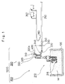
- Fig. 5 is an entire structural view of solidification and pneumatic transportation equipment
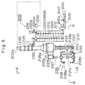
- Fig. 6 is a vertical sectional view showing in detail main elements of the solidification and pneumatic transportation equipment
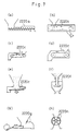
- Fig. 7 is a schematic view illustrating various types of stabilizer feeders.
- the mud kneading apparatus 2300 is connected to the discharge opening 2125 of the vertical screw conveyor 2120 to follow it.
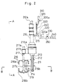
- a vertical double-shaft paddle mixer as shown in Fig. 5 and Fig. 6, or a horizontal double-shaft paddle mixer is preferably employed as the mud kneading apparatus 2300, another type of kneading apparatus may also be employed.
- the vertical double-shaft paddle mixer 2300A two vertical rotary shafts 2310 are supported in parallel within the casing having an elliptical section so that the vertical rotary shafts 2310 can freely rotate in the direction opposite to each other.
- Each rotary shaft 2310 is provided with a plurality of paddle blades 2320 roughly at intervals.
- the mud pneumatic transporting apparatus 2400 comprises a pressure pump 2410 following the mud kneading apparatus 2300, a tube 2420 for transporting soft mud after the pressure pump 2410, an ejector 2430 disposed on the way of the tube 2420 for supplying compressed air, and compressors 2432 as a supply source of compressed air.
- the soft mud sufficiently uniformly mixed with the stabilizer in the mud kneading apparatus 2300 is pressurized by the pressure pump 2410, transported downstream through the tube 2420, and further pneumatically transported by a plug transportation with compressed air injected from the ejector 2430 to a distant destination.
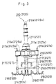
- the vertical screw conveyor 2120 according to the embodiment of this invention comprises the vertical cylindrical casing 2121 and the rotary shaft 2122 having the helical screw blade 2123 disposed around the periphery of the rotary shaft 2122 concentrically with the casing 2121 as shown in Fig. 3 and Fig. 4.
- the rotary shaft 2122 is rotatably supported by shaft bearings disposed at upper and lower ends of the casing 2121 and is driven by a hydraulic motor 2122a at the top thereof to rotate with its speed adjustable. Therefore, the vertical screw conveyor 2120 discharges soft mud, sucked up through the suction opening 2124 formed in the bottom thereof, from the discharge opening 2125 and, as mentioned above, sends the soft mud to the mud kneading apparatus 2300.
- the speed of revolution of the vertical screw conveyor 2120 is variable in a range between 400 and 1,200 rpm.
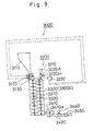
- a flowmeter 3130 for measuring the flow rate of soft mud is disposed between the flow control means 3120 and the mud kneading apparatus 3300.
- a motor 3220m is controlled by a control apparatus 3230 to rotate at the speed of revolution to provide the stabilizer in the volume corresponding to the flow rate.
- the results are checked by a flowmeter 3440 arranged behind a pressure pump 3410.
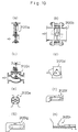
- Fig. 11 and Fig. 12 are illustrated with regard to the embodiment of the present invention (IV), Fig. 11 is an entire structural view of solidification and pneumatic transportation equipment, and Fig. 12 is a vertical sectional view showing in detail main elements of the solidification and pneumatic transportation equipment.
- the stabilizer may be fed in powder form, it is sometimes better due to the soil condition of soft mud for uniformly mixing them with the soft mud that the stabilizer are fed in the form of slurries by adding water therein.
- the stabilizer feeder 4320 has a storage tank with a mixer and a water supply line connected to the storage tank and then makes stabilizer in the form of slurries.
- the stabilizer in the form of slurries are discharged by a piston pump.
- the stabilizer are added at the ratio of 50 - 200 kg (usually 100 kg) to the soft mud of 1 m3.
Landscapes
- Chemical & Material Sciences (AREA)
- Life Sciences & Earth Sciences (AREA)
- Hydrology & Water Resources (AREA)
- Engineering & Computer Science (AREA)
- Environmental & Geological Engineering (AREA)
- Water Supply & Treatment (AREA)
- Organic Chemistry (AREA)
- Chemical Kinetics & Catalysis (AREA)
- Dispersion Chemistry (AREA)
- Treatment Of Sludge (AREA)
- Feeding, Discharge, Calcimining, Fusing, And Gas-Generation Devices (AREA)
Applications Claiming Priority (8)
| Application Number | Priority Date | Filing Date | Title |
|---|---|---|---|
| JP209728/94 | 1994-09-02 | ||
| JP20972894A JPH0871595A (ja) | 1994-09-02 | 1994-09-02 | 軟泥の固化処理圧送設備 |
| JP249189/94 | 1994-10-14 | ||
| JP24918994A JPH08108200A (ja) | 1994-10-14 | 1994-10-14 | 軟泥の固化処理圧送設備 |
| JP25703894A JPH08117798A (ja) | 1994-10-21 | 1994-10-21 | 軟泥の固化処理圧送設備 |
| JP257038/94 | 1994-10-21 | ||
| JP26526894A JPH08126899A (ja) | 1994-10-28 | 1994-10-28 | 軟泥の固化処理圧送設備 |
| JP265268/94 | 1994-10-28 |
Publications (2)
| Publication Number | Publication Date |
|---|---|
| EP0699633A2 true EP0699633A2 (de) | 1996-03-06 |
| EP0699633A3 EP0699633A3 (de) | 1996-03-20 |
Family
ID=27476472
Family Applications (1)
| Application Number | Title | Priority Date | Filing Date |
|---|---|---|---|
| EP95305575A Ceased EP0699633A2 (de) | 1994-09-02 | 1995-08-10 | Vorrichtung zur Verfestigung und pneumatischen Förderung von Schlämmen |
Country Status (2)
| Country | Link |
|---|---|
| EP (1) | EP0699633A2 (de) |
| KR (1) | KR960010554A (de) |
Cited By (5)
| Publication number | Priority date | Publication date | Assignee | Title |
|---|---|---|---|---|
| FR2853310A1 (fr) * | 2003-04-04 | 2004-10-08 | Sogea Atlantique | Brassage mecanique et aeration forcee simultanes de boues de station d'epuration |
| WO2016161053A1 (en) * | 2015-04-01 | 2016-10-06 | Welsh Brian | Soil remediation method |
| CN107935338A (zh) * | 2018-01-10 | 2018-04-20 | 广东鼎瑞建设工程有限公司 | 一种管道淤泥固化处理设备及其施工方法 |
| CN111501863A (zh) * | 2020-04-30 | 2020-08-07 | 河南理工大学 | 一种冻结岩土人工智能综合连续掘进机 |
| CN117534271A (zh) * | 2023-08-28 | 2024-02-09 | 山东省煤田地质局第二勘探队 | 一种泥浆净化器的进料装置 |
Family Cites Families (6)
| Publication number | Priority date | Publication date | Assignee | Title |
|---|---|---|---|---|
| JPS5337579A (en) * | 1976-09-20 | 1978-04-06 | Toyo Construction | Apparatus for treating sludges |
| JPH02194898A (ja) * | 1989-01-24 | 1990-08-01 | Ube Ind Ltd | 軟泥の固化混練装置 |
| JPH02198700A (ja) * | 1989-01-27 | 1990-08-07 | Ube Ind Ltd | 軟泥の固化混練装置 |
| JPH02203997A (ja) * | 1989-01-31 | 1990-08-13 | Ube Ind Ltd | 軟泥の固化混練装置 |
| US4981600A (en) * | 1989-11-13 | 1991-01-01 | Cemen-Tech, Inc. | Method and means for treating sludge |
| JPH0420706A (ja) * | 1990-05-15 | 1992-01-24 | Ube Ind Ltd | 脱水汚泥の管路圧送装置 |
-
1995
- 1995-08-10 EP EP95305575A patent/EP0699633A2/de not_active Ceased
- 1995-08-23 KR KR1019950026106A patent/KR960010554A/ko not_active Withdrawn
Non-Patent Citations (1)
| Title |
|---|
| None |
Cited By (5)
| Publication number | Priority date | Publication date | Assignee | Title |
|---|---|---|---|---|
| FR2853310A1 (fr) * | 2003-04-04 | 2004-10-08 | Sogea Atlantique | Brassage mecanique et aeration forcee simultanes de boues de station d'epuration |
| WO2016161053A1 (en) * | 2015-04-01 | 2016-10-06 | Welsh Brian | Soil remediation method |
| CN107935338A (zh) * | 2018-01-10 | 2018-04-20 | 广东鼎瑞建设工程有限公司 | 一种管道淤泥固化处理设备及其施工方法 |
| CN111501863A (zh) * | 2020-04-30 | 2020-08-07 | 河南理工大学 | 一种冻结岩土人工智能综合连续掘进机 |
| CN117534271A (zh) * | 2023-08-28 | 2024-02-09 | 山东省煤田地质局第二勘探队 | 一种泥浆净化器的进料装置 |
Also Published As
| Publication number | Publication date |
|---|---|
| EP0699633A3 (de) | 1996-03-20 |
| KR960010554A (ko) | 1996-04-20 |
Similar Documents
| Publication | Publication Date | Title |
|---|---|---|
| JP4188151B2 (ja) | スクリューコンベア式連続攪拌装置 | |
| JP6626144B2 (ja) | 管路ミキサ及びこれを用いた混合物の製造供給方法 | |
| EP0699633A2 (de) | Vorrichtung zur Verfestigung und pneumatischen Förderung von Schlämmen | |
| CN219213573U (zh) | 多混频器式流化处理装置 | |
| JP2000345578A (ja) | 流動化処理土製造装置及びその製造方法 | |
| CN115366255A (zh) | 一种多混频器式流化处理装置 | |
| JPH0813541A (ja) | 軟泥の固化処理圧送装置 | |
| JP3820467B2 (ja) | 土工事用流動化処理土の製造方法及び装置 | |
| JPH084051A (ja) | 軟泥の固化処理圧送装置 | |
| JP2826166B2 (ja) | 泥土処理装置 | |
| JPH08108200A (ja) | 軟泥の固化処理圧送設備 | |
| CN210597435U (zh) | 一种水利施工高效清淤设备 | |
| JPH0820965A (ja) | 浚渫圧送装置 | |
| JPH10147286A (ja) | 軟泥固化処理圧送船 | |
| JP3344711B2 (ja) | 攪拌・混合式土質改良機械 | |
| JPH0871595A (ja) | 軟泥の固化処理圧送設備 | |
| CN210340643U (zh) | 一种土壤修复用淤泥固化搅拌机 | |
| JPH08117798A (ja) | 軟泥の固化処理圧送設備 | |
| CN221391570U (zh) | 一种连续上料制浆和输送塑性浆体的设备 | |
| JPH02198700A (ja) | 軟泥の固化混練装置 | |
| JPH084052A (ja) | 泥土固化圧送装置 | |
| JPH0820966A (ja) | 浚渫圧送装置 | |
| JP2005113511A (ja) | 泥土改良方法 | |
| JPH08126899A (ja) | 軟泥の固化処理圧送設備 | |
| JPH0663261B2 (ja) | 土砂の圧送方法およびその装置 |
Legal Events
| Date | Code | Title | Description |
|---|---|---|---|
| PUAI | Public reference made under article 153(3) epc to a published international application that has entered the european phase |
Free format text: ORIGINAL CODE: 0009012 |
|
| PUAL | Search report despatched |
Free format text: ORIGINAL CODE: 0009013 |
|
| AK | Designated contracting states |
Kind code of ref document: A2 Designated state(s): DE FR GB NL |
|
| AK | Designated contracting states |
Kind code of ref document: A3 Designated state(s): DE FR GB NL |
|
| 17P | Request for examination filed |
Effective date: 19960429 |
|
| GRAG | Despatch of communication of intention to grant |
Free format text: ORIGINAL CODE: EPIDOS AGRA |
|
| 17Q | First examination report despatched |
Effective date: 19980915 |
|
| STAA | Information on the status of an ep patent application or granted ep patent |
Free format text: STATUS: THE APPLICATION HAS BEEN REFUSED |
|
| 18R | Application refused |
Effective date: 19990126 |