EP0698743A2 - Lagerbuchse - Google Patents
Lagerbuchse Download PDFInfo
- Publication number
- EP0698743A2 EP0698743A2 EP95112249A EP95112249A EP0698743A2 EP 0698743 A2 EP0698743 A2 EP 0698743A2 EP 95112249 A EP95112249 A EP 95112249A EP 95112249 A EP95112249 A EP 95112249A EP 0698743 A2 EP0698743 A2 EP 0698743A2
- Authority
- EP
- European Patent Office
- Prior art keywords
- tube
- inner tube
- bearing bush
- intermediate tube
- vulcanization
- Prior art date
- Legal status (The legal status is an assumption and is not a legal conclusion. Google has not performed a legal analysis and makes no representation as to the accuracy of the status listed.)
- Granted
Links
Images


Classifications
-
- F—MECHANICAL ENGINEERING; LIGHTING; HEATING; WEAPONS; BLASTING
- F16—ENGINEERING ELEMENTS AND UNITS; GENERAL MEASURES FOR PRODUCING AND MAINTAINING EFFECTIVE FUNCTIONING OF MACHINES OR INSTALLATIONS; THERMAL INSULATION IN GENERAL
- F16C—SHAFTS; FLEXIBLE SHAFTS; ELEMENTS OR CRANKSHAFT MECHANISMS; ROTARY BODIES OTHER THAN GEARING ELEMENTS; BEARINGS
- F16C33/00—Parts of bearings; Special methods for making bearings or parts thereof
- F16C33/02—Parts of sliding-contact bearings
- F16C33/04—Brasses; Bushes; Linings
-
- F—MECHANICAL ENGINEERING; LIGHTING; HEATING; WEAPONS; BLASTING
- F16—ENGINEERING ELEMENTS AND UNITS; GENERAL MEASURES FOR PRODUCING AND MAINTAINING EFFECTIVE FUNCTIONING OF MACHINES OR INSTALLATIONS; THERMAL INSULATION IN GENERAL
- F16F—SPRINGS; SHOCK-ABSORBERS; MEANS FOR DAMPING VIBRATION
- F16F1/00—Springs
- F16F1/36—Springs made of rubber or other material having high internal friction, e.g. thermoplastic elastomers
- F16F1/38—Springs made of rubber or other material having high internal friction, e.g. thermoplastic elastomers with a sleeve of elastic material between a rigid outer sleeve and a rigid inner sleeve or pin, i.e. bushing-type
- F16F1/3863—Springs made of rubber or other material having high internal friction, e.g. thermoplastic elastomers with a sleeve of elastic material between a rigid outer sleeve and a rigid inner sleeve or pin, i.e. bushing-type characterised by the rigid sleeves or pin, e.g. of non-circular cross-section
-
- B—PERFORMING OPERATIONS; TRANSPORTING
- B60—VEHICLES IN GENERAL
- B60G—VEHICLE SUSPENSION ARRANGEMENTS
- B60G7/00—Pivoted suspension arms; Accessories thereof
- B60G7/02—Attaching arms to sprung part of vehicle
-
- F—MECHANICAL ENGINEERING; LIGHTING; HEATING; WEAPONS; BLASTING
- F16—ENGINEERING ELEMENTS AND UNITS; GENERAL MEASURES FOR PRODUCING AND MAINTAINING EFFECTIVE FUNCTIONING OF MACHINES OR INSTALLATIONS; THERMAL INSULATION IN GENERAL
- F16C—SHAFTS; FLEXIBLE SHAFTS; ELEMENTS OR CRANKSHAFT MECHANISMS; ROTARY BODIES OTHER THAN GEARING ELEMENTS; BEARINGS
- F16C27/00—Elastic or yielding bearings or bearing supports, for exclusively rotary movement
- F16C27/06—Elastic or yielding bearings or bearing supports, for exclusively rotary movement by means of parts of rubber or like materials
- F16C27/063—Sliding contact bearings
-
- F—MECHANICAL ENGINEERING; LIGHTING; HEATING; WEAPONS; BLASTING
- F16—ENGINEERING ELEMENTS AND UNITS; GENERAL MEASURES FOR PRODUCING AND MAINTAINING EFFECTIVE FUNCTIONING OF MACHINES OR INSTALLATIONS; THERMAL INSULATION IN GENERAL
- F16C—SHAFTS; FLEXIBLE SHAFTS; ELEMENTS OR CRANKSHAFT MECHANISMS; ROTARY BODIES OTHER THAN GEARING ELEMENTS; BEARINGS
- F16C33/00—Parts of bearings; Special methods for making bearings or parts thereof
- F16C33/02—Parts of sliding-contact bearings
- F16C33/04—Brasses; Bushes; Linings
- F16C33/20—Sliding surface consisting mainly of plastics
-
- F—MECHANICAL ENGINEERING; LIGHTING; HEATING; WEAPONS; BLASTING
- F16—ENGINEERING ELEMENTS AND UNITS; GENERAL MEASURES FOR PRODUCING AND MAINTAINING EFFECTIVE FUNCTIONING OF MACHINES OR INSTALLATIONS; THERMAL INSULATION IN GENERAL
- F16F—SPRINGS; SHOCK-ABSORBERS; MEANS FOR DAMPING VIBRATION
- F16F1/00—Springs
- F16F1/36—Springs made of rubber or other material having high internal friction, e.g. thermoplastic elastomers
- F16F1/38—Springs made of rubber or other material having high internal friction, e.g. thermoplastic elastomers with a sleeve of elastic material between a rigid outer sleeve and a rigid inner sleeve or pin, i.e. bushing-type
- F16F1/3842—Method of assembly, production or treatment; Mounting thereof
-
- B—PERFORMING OPERATIONS; TRANSPORTING
- B60—VEHICLES IN GENERAL
- B60G—VEHICLE SUSPENSION ARRANGEMENTS
- B60G2204/00—Indexing codes related to suspensions per se or to auxiliary parts
- B60G2204/40—Auxiliary suspension parts; Adjustment of suspensions
- B60G2204/41—Elastic mounts, e.g. bushings
-
- B—PERFORMING OPERATIONS; TRANSPORTING
- B60—VEHICLES IN GENERAL
- B60G—VEHICLE SUSPENSION ARRANGEMENTS
- B60G2204/00—Indexing codes related to suspensions per se or to auxiliary parts
- B60G2204/40—Auxiliary suspension parts; Adjustment of suspensions
- B60G2204/44—Centering or positioning means
-
- F—MECHANICAL ENGINEERING; LIGHTING; HEATING; WEAPONS; BLASTING
- F16—ENGINEERING ELEMENTS AND UNITS; GENERAL MEASURES FOR PRODUCING AND MAINTAINING EFFECTIVE FUNCTIONING OF MACHINES OR INSTALLATIONS; THERMAL INSULATION IN GENERAL
- F16C—SHAFTS; FLEXIBLE SHAFTS; ELEMENTS OR CRANKSHAFT MECHANISMS; ROTARY BODIES OTHER THAN GEARING ELEMENTS; BEARINGS
- F16C2326/00—Articles relating to transporting
- F16C2326/01—Parts of vehicles in general
- F16C2326/05—Vehicle suspensions, e.g. bearings, pivots or connecting rods used therein
-
- Y—GENERAL TAGGING OF NEW TECHNOLOGICAL DEVELOPMENTS; GENERAL TAGGING OF CROSS-SECTIONAL TECHNOLOGIES SPANNING OVER SEVERAL SECTIONS OF THE IPC; TECHNICAL SUBJECTS COVERED BY FORMER USPC CROSS-REFERENCE ART COLLECTIONS [XRACs] AND DIGESTS
- Y10—TECHNICAL SUBJECTS COVERED BY FORMER USPC
- Y10T—TECHNICAL SUBJECTS COVERED BY FORMER US CLASSIFICATION
- Y10T29/00—Metal working
- Y10T29/49—Method of mechanical manufacture
- Y10T29/49636—Process for making bearing or component thereof
- Y10T29/49643—Rotary bearing
- Y10T29/49647—Plain bearing
- Y10T29/49668—Sleeve or bushing making
- Y10T29/4967—Nonmetallic
Definitions
- the invention relates to a bearing bush and a method for the production thereof.
- Known bearing bushes which are used in particular in motor vehicles, have an inner tube made of metal and an outer tube likewise made of metal and surrounding the inner tube, a vulcanization layer being provided between the inner tube and the outer tube.
- the invention has for its object to propose a bearing bush in which the outer tube can be rotated relative to the inner tube in the event of torsional stress and which can be produced in a simple manner.
- the bearing bush according to the invention has an inner tube made of metal, and an intermediate tube made of plastic, which is slidably seated on the inner tube at least in the circumferential direction, the inside of which is shaped in accordance with the outer contour of the inner tube and a vulcanization layer is applied to the outside.
- the inner tube can thus be rotated relative to the intermediate tube and the vulcanization layer connected to it.
- a bearing bush has a particularly simple structure and can be manufactured in a simple manner. Since the intermediate tube is made of plastic, it can already be inserted into the vulcanization mold during vulcanization, which means that the intermediate tube is already adapted to the outer contour of the inner tube during the vulcanization process. Plastics with low coefficients of friction, for example polyamide, are advantageously used for the intermediate tube.
- Axial securing of the intermediate tube and the parts connected to it can be achieved in a simple manner in that the inner tube has an outer contour securing the intermediate tube in the axial direction.
- the inner tube can expediently have at least one end bevel on which the intermediate tube rests. In these configurations, too, the intermediate tube is already inserted into the vulcanization mold during vulcanization and deformed in accordance with the outer contour of the inner tube.
- the inner tube can have a curved outer contour in order to allow a cardanic deflection of the intermediate tube seated on the inner tube.
- the vulcanization layer can advantageously be formed with a laterally projecting sealing lip.
- the outside of the intermediate tube can be provided with an adhesive.
- the bearing bush can also have an outer tube connected to the vulcanization layer.
- This can consist of metal, but also of plastic or other materials.
- the inner tube and the intermediate tube made of plastic are placed together in the vulcanization mold, the intermediate tube being correspondingly deformed during the vulcanization of the outer contour of the inner tube.
- the intermediate tube made of plastic is deformed essentially free of play in accordance with the outer contour of the inner tube.
- the intermediate tube can be rotated in the circumferential direction relative to the inner tube.
- An adhesive is advantageously applied to the outside of the intermediate tube, which improves the connection to the vulcanization layer.
- the bearing bush shown in Fig. 1 has a cylindrical inner tube 10 made of metal. On the outer circumference of the inner tube 10, there is an intermediate tube 11 made of plastic, which is rotatable in the circumferential direction relative to the inner tube 10. A vulcanization layer 12 is applied to the outside of the intermediate tube 11, a suitable adhesive being able to be used to improve the adhesive properties.
- the intermediate tube 11 is connected via the vulcanization layer 12 made of rubber-elastic material to an outer tube 13 made of metal.
- this arrangement permits a relative rotation of the intermediate tube 11 and of the outer tube connected to it via the vulcanization layer 12 when the bearing bush is subjected to torsional stress 13.
- a circumferential groove 14, 15 is formed on the vulcanization layer 12 on the opposite end faces.
- the bearing bush shown in Fig. 2 has an inner tube 10 made of metal, which is provided at the end with bevels 16, 17 which converge with respect to a longitudinal axis 18 of the bearing bush.
- the intermediate tube 11 made of plastic sits on the bevels 16, 17 without play. This ensures that the intermediate tube 11 and the outer tube connected to it via the vulcanization layer 12 are secured in the axial direction with respect to the inner tube 10. In the circumferential direction, the intermediate tube 11 and the parts connected to it are arranged such that they can rotate with respect to the inner tube 10.
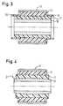
- the bearing bush shown in FIG. 3 has a structure similar to that of the bearing bush according to FIG. 1.
- the bearing bush according to FIG. 3 has laterally projecting sealing lips 19, 20 which start from the vulcanization layer 12.
- the sealing lips 19, 20 protrude beyond the end region of the inner tube 10 and the intermediate tube 12 made of plastic and seated thereon.
- FIG. 4 shows a further embodiment of a bearing bush according to the invention, in which the inner tube 10 made of metal has a curved outer contour 21.
- the intermediate tube 11 made of plastic sits on the outside of the inner tube 10 without play on.
- the intermediate tube 11 is connected to the outer tube 13 via the vulcanization layer 12.
- This configuration of the inner tube 10 with a curved outer contour enables a cardanic deflection of the intermediate tube 11 seated on the inner tube 10 and the parts connected to it.
- Fig. 5 shows an embodiment in which no outer tube is provided.
- the cylindrical intermediate tube 11 is slidably seated on the inside of the inner tube 10.
- the intermediate tube 11 is vulcanized with a vulcanization layer 12 which is shaped in such a way that it can be pressed directly into a receptacle.
- projections 22, 23 are formed on the vulcanization layer 12.
- the inner tube 10 made of metal is inserted into the vulcanization mold together with the intermediate tube 11 made of plastic.
- the intermediate tube 11 made of plastic is pressed onto the inner tube 10 made of metal.
- the inside of the intermediate tube 11 made of plastic takes on the shape of the outer contour of the metallic inner tube 10.
- An adhesive is applied to the outside of the intermediate tube 11 in order to improve the adhesion to the vulcanization layer 12.
Landscapes
- Engineering & Computer Science (AREA)
- General Engineering & Computer Science (AREA)
- Mechanical Engineering (AREA)
- Manufacturing & Machinery (AREA)
- Sliding-Contact Bearings (AREA)
- Springs (AREA)
- Moulds For Moulding Plastics Or The Like (AREA)
- Heating, Cooling, Or Curing Plastics Or The Like In General (AREA)
Abstract
Description
- Die Erfindung betrifft eine Lagerbuchse und ein Verfahren zu deren Herstellung.
- Bekannte Lagerbuchsen, die insbesondere bei Kraftfahrzeugen zum Einsatz kommen, besitzen ein Innenrohr aus Metall und ein ebenfalls aus Metall hergestelltes, das Innenrohr umgebende Außenrohr, wobei zwischen Innenrohr und Außenrohr eine Vulkanisationsschicht vorgesehen ist.
- Der Erfindung liegt die Aufgabe zugrunde, eine Lagerbuchse vorzuschlagen, bei der bei einer Torsionsbeanspruchung das Außenrohr relativ zum Innenrohr drehbar ist und das in einfacher Weise herstellbar ist.
- Zur Lösung dieser Aufgabe wird eine Lagerbuchse mit den Merkmalen des Patentanspruches 1 vorgeschlagen. Die erfindungsgemäße Lagerbuchse weist ein Innenrohr aus Metall, und ein auf dem Innenrohr mindestens in Umfangsrichtung gleitbeweglich aufsitzendes Zwischenrohr aus Kunststoff auf, dessen Innenseite entsprechend der Außenkontur des Innenrohres geformt ist und an dessen Außenseite eine Vulkanisationsschicht aufgebracht ist.
- Bei einer Torsionsbeanspruchung kann somit das Innenrohr relativ zu dem Zwischenrohr und der hiermit verbundenen Vulkanisationsschicht verdreht werden. Eine derartige Lagerbuchse besitzt einen besonders einfachen Aufbau und kann in einfacher Weise hergestellt werden. Da das Zwischenrohr aus Kunststoff besteht, kann es bereits bei der Vulkanisation in die Vulkanisationsform eingelegt werden, wodurch bereits während des Vulkanisationsvorganges eine Anpassung des Zwischenrohres an die Außenkontur des Innenrohres erfolgt. Vorteilhaft werden für das Zwischenrohr Kunststoffe mit niedrigen Reibwerten, beispielsweise Polyamid verwendet.
- Vorteilhafte Ausgestaltungen der Erfindung sind in den Unteransprüchen aufgeführt.
- In einfacher Weise kann eine axiale Sicherung des Zwischenrohres und der hiermit verbundenen Teile dadurch erreicht werden, daß das Innenrohr eine das Zwischenrohr in axialer Richtung sichernde Außenkontur aufweist. Zweckmäßig kann das Innenrohr mindestens eine endseitige Abschrägung aufweisen, auf der das Zwischenrohr aufliegt. Auch bei diesen Ausgestaltungen wird das Zwischenrohr bereits während der Vulkanisation in die Vulkanisationsform eingelegt und entsprechend der Außenkontur des Innenrohres verformt.
- Bei einer weiteren Ausgestaltung kann das Innenrohr eine gebogene Außenkontur aufweisen, um eine kardanische Auslenkung des auf dem Innenrohr aufsitzenden Zwischenrohres zu ermöglichen.
- Vorteilhaft kann die Vulkanisationsschicht mit einer seitlich abragenden Dichtlippe ausgebildet sein.
- Um eine besonders gute Verbindung zur Vulkanisationsschicht zu gewährleisten, kann die Außenseite des Zwischenrohres mit einem Haftmittel versehen sein.
- In weiterer Ausgestaltung kann die Lagerbuchse auch ein mit der Vulkanisationsschicht verbundenes Außenrohr aufweisen. Dieses kann aus Metall, aber auch aus Kunststoff oder anderen Materialien bestehen.
- Bei einem erfindungsgemäßen Verfahren zur Herstellung einer derartigen Lagerbuchse ist vorgesehen, daß das Innenrohr und das Zwischenrohr aus Kunststoff zusammen in die Vulkanisationsform eingelegt werden, wobei während der Vulkanisation das Zwischenrohr der Außenkontur des Innenrohres entsprechend verformt wird. Bei dem Vulkanisationsvorgang wird das Zwischenrohr aus Kunststoff im wesentlichen spielfrei entsprechend der Außenkontur des Innenrohres verformt. Nach der Vulkanisation ist das Zwischenrohr in Umfangsrichtung relativ zu dem Innenrohr drehbar.
- Vorteilhaft wird auf die Außenseite des Zwischenrohres ein Haftmittel aufgebracht, das die Verbindung zur Vulkanisationsschicht verbessert.
- Nachfolgend wird die Erfindung anhand vorteilhafter Ausführungsformen beschrieben, die in der Zeichnung in schematischer Weise dargestellt sind.
- Hierin zeigen:
- Fig. 1
- einen Vertikalschnitt durch eine erste Ausführungsform der erfindungsgemäßen Lagerbuchse,
- Fig. 2
- einen Vertikalschnitt durch eine zweite Ausführungsform der erfindungsgemäßen Lagerbuchse, bei der das Innenrohr zur axialen Sicherung des Zwischenrohres endseitige Abschrägungen aufweist,
- Fig. 3
- einen Vertikalschnitt durch eine dritte Ausführungsform der erfindungsgemäßen Lagerbuchse, bei der die Vulkanisationsschicht endseitige Dichtlippen aufweist,
- Fig. 4
- einen Vertikalschnitt durch eine vierte Ausführungsform der erfindungsgemäßen Lagerbuchse, bei der das Innenrohr eine gebogene Außenkontur aufweist, um eine kardanische Auslenkung des hierauf aufsitzenden Zwischenrohres und der hiermit verbundenen Teile zu ermöglichen, und
- Fig. 5
- einen Vertikalschnitt durch eine weitere Ausführungsform der erfindungsgemäßen Lagerbuchse, bei der kein Außenrohr vorgesehen ist.
- Für die nachfolgende Figurenbeschreibung der in den Figuren 1 bis 4 dargestellten Ausführungsformen der erfindungsgemäßen Lagerbuchse werden für gleiche oder gleichartige Teile identische Bezugszeichen verwendet.
- Die in Fig. 1 dargestellte Lagerbuchse besitzt ein zylinderförmiges Innenrohr 10 aus Metall. Am Außenumfang des Innenrohres 10 sitzt spielfrei ein Zwischenrohr 11 aus Kunststoff auf, das relativ zu dem Innenrohr 10 in Umfangsrichtung drehbeweglich ist. Auf die Außenseite des Zwischenrohres 11 ist eine Vulkanisationsschicht 12 aufgebracht, wobei zur Verbesserung der Hafteigenschaften ein geeignetes Haftmittel zum Einsatz kommen kann.
- Das Zwischenrohr 11 ist über die Vulkanisationsschicht 12 aus gummielastischem Material mit einem Außenrohr 13 aus Metall verbunden. Somit gestattet diese Anordnung bei einer Torsionsbeanspruchung der Lagerbuchse eine relative Verdrehung des Zwischenrohres 11 und des über die Vulkanisationsschicht 12 hiermit verbundenen Außenrohres 13. An den gegenüberliegenden Stirnseiten ist an der Vulkanisationsschicht 12 eine Umfangsnut 14, 15 ausgebildet.
- Die in Fig. 2 dargestellte Lagerbuchse weist ein Innenrohr 10 aus Metall auf, das endseitig mit Abschrägungen 16, 17 versehen ist, die bezüglich einer Längsachse 18 der Lagerbuchse konvergieren. Wie aus Fig. 2 hervorgeht, sitzt das Zwischenrohr 11 aus Kunststoff spielfrei auf den Abschrägungen 16, 17 auf. Hierdurch wird gewährleistet, daß das Zwischenrohr 11 und das hiermit über die Vulkanisationsschicht 12 verbundene Außenrohr in axialer Richtung bezüglich des Innenrohres 10 gesichert ist. In Umfangsrichtung ist das Zwischenrohr 11 und die hiermit verbundenen Teile bezüglich des Innenrohres 10 drehbeweglich angeordnet.
- Die in Fig. 3 dargestellte Lagerbuchse besitzt einen ähnlichen Aufbau wie die Lagerbuchse gemäß Fig. 1. Im Unterschied hierzu weist die Lagerbuchse gemäß Fig. 3 seitlich abragende Dichtlippen 19, 20 auf, die von der Vulkanisationsschicht 12 ausgehen. Wie aus Fig. 3 hervorgeht, überragen die Dichtlippen 19, 20 den Endbereich des Innenrohres 10 und des hierauf aufsitzenden Zwischenrohres 12 aus Kunststoff.
- Fig. 4 zeigt eine weitere Ausführungsform einer erfindungsgemäßen Lagerbuchse, bei der das Innenrohr 10 aus Metall eine gebogene Außenkontur 21 aufweist. Wie aus Fig. 4 hervorgeht, sitzt das Zwischenrohr 11 aus Kunststoff spielfrei auf der Außenseite des Innenrohres 10 auf. Über die Vulkanisationsschicht 12 ist das Zwischenrohr 11 mit dem Außenrohr 13 verbunden. Durch diese Ausgestaltung des Innenrohres 10 mit einer gebogenen Außenkontur wird eine kardanische Auslenkung des auf dem Innenrohr 10 aufsitzenden Zwischenrohres 11 und der hiermit verbundenen Teile ermöglicht.
- Fig. 5 zeigt eine Ausführungsform, bei der kein Außenrohr vorgesehen ist. Das zylindrische Zwischenrohr 11 sitzt an seiner Innenseite gleitbeweglich auf dem Innenrohr 10 auf. Das Zwischenrohr 11 ist mit einer Vulkanisationsschicht 12 vulkanisiert, die derart geformt ist, daß ein direktes Eindrücken in eine Aufnahme möglich ist. Hierzu sind an der Vulkanisationsschicht 12 Ansätze 22, 23 angeformt.
- Nachfolgend soll das Herstellungsverfahren für die in den Fig. 1 bis 5 dargestellten Lagerbuchsen beschrieben werden. Bei der Herstellung wird das Innenrohr 10 aus Metall zusammen mit dem Zwischenrohr 11 aus Kunststoff in die Vulkanisationsform eingelegt. Bei der Vulkanisation wird das Zwischenrohr 11 aus Kunststoff auf das Innenrohr 10 aus Metall aufgepreßt. Hierbei nimmt die Innenseite des Zwischenrohres 11 aus Kunststoff die Form der Außenkontur des metallischen Innenrohres 10 an. Auf der Außenseite des Zwischenrohres 11 wird ein Haftmittel aufgebracht, um die Haftung zu der Vulkanisationsschicht 12 zu verbessern.
Claims (9)
- Lagerbuchse, insbesondere für Kraftfahrzeuge, mit einem Innenrohr (10) aus Metall, und einem auf dem Innenrohr (10) mindestens in Umfangsrichtung gleitbeweglich aufsitzenden Zwischenrohr (11) aus Kunststoff, dessen Innenseite entsprechend der Außenkontur des Innenrohres (10) geformt ist und an dessen Außenseite eine Vulkanisationsschicht (12) aufgebracht ist.
- Lagerbuchse nach Anspruch 1, dadurch gekennzeichnet, daß das Innenrohr (10) eine das Zwischenrohr (11) in axialer Richtung sichernde Außenkontur (21) aufweist.
- Lagerbuchse nach Anspruch 1 oder 2, dadurch gekennzeichnet, daß das Innenrohr (10) mindestens eine endseitige Abschrägung (16, 17) aufweist, auf der das Zwischenrohr (11) aufliegt.
- Lagerbuchse nach einem der Ansprüche 1 bis 3, dadurch gekennzeichnet, daß das Innenrohr (10) eine gebogene Außenkontur (21) aufweist, um eine kardanische Auslenkung des auf dem Innenrohr (10) aufsitzenden Zwischenrohres (11) zu ermöglichen.
- Lagerbuchse nach einem der Ansprüche 1 bis 4, dadurch gekennzeichnet, daß die Vulkanisationsschicht (12) mit einer seitlich abragenden Dichtlippe (19, 20) ausgebildet ist.
- Lagerbuchse nach einem der Ansprüche 1 bis 5, dadurch gekennzeichnet, daß die Außenseite des Zwischenrohres (11) mit einem Haftmittel versehen ist, das die Verbindung zur Vulkanisationsschicht (12) verbessert.
- Lagerbuchse nach einem der Ansprüche 1 bis 5, dadurch gekennzeichnet, daß ein mit der Vulkanisationsschicht (12) verbundenes Außenrohr (13) vorgesehen ist.
- Verfahren zur Herstellung einer Lagerbuchse nach einem oder mehreren der Ansprüche 1 bis 7, dadurch gekennzeichnet, daß das Innenrohr (10) und das Zwischenrohr (11) aus Kunststoff zusammen in die Vulkanisationsform eingelegt werden, wobei während der Vulkanisation das Zwischenrohr (11) der Außenkontur (21) des Innenrohres (10) entsprechend verformt wird.
- Verfahren nach Anspruch 8, dadurch gekennzeichnet, daß auf die Außenseite des Zwischenrohres (11) ein Haftmittel aufgebracht wird, das die Verbindung zur Vulkanisationsschicht (12) verbessert.
Applications Claiming Priority (2)
| Application Number | Priority Date | Filing Date | Title |
|---|---|---|---|
| DE4430037 | 1994-08-24 | ||
| DE4430037A DE4430037C2 (de) | 1994-08-24 | 1994-08-24 | Lagerbuchse |
Publications (3)
| Publication Number | Publication Date |
|---|---|
| EP0698743A2 true EP0698743A2 (de) | 1996-02-28 |
| EP0698743A3 EP0698743A3 (de) | 1997-05-07 |
| EP0698743B1 EP0698743B1 (de) | 1999-12-08 |
Family
ID=6526457
Family Applications (1)
| Application Number | Title | Priority Date | Filing Date |
|---|---|---|---|
| EP95112249A Revoked EP0698743B1 (de) | 1994-08-24 | 1995-08-03 | Lagerbuchse und Verfahren zu deren Herstellung |
Country Status (7)
| Country | Link |
|---|---|
| US (1) | US5620261A (de) |
| EP (1) | EP0698743B1 (de) |
| JP (1) | JPH0866978A (de) |
| KR (1) | KR960008101A (de) |
| BR (1) | BR9503761A (de) |
| DE (2) | DE4430037C2 (de) |
| ES (1) | ES2140590T3 (de) |
Cited By (6)
| Publication number | Priority date | Publication date | Assignee | Title |
|---|---|---|---|---|
| WO1997036120A1 (en) * | 1996-03-25 | 1997-10-02 | F.I.B.E.T. S.P.A. | Mechanical coupling for elastic axial and radial constraint with torsional freedom, especially for elastic pivots and suspensions and the like |
| FR2766247A1 (fr) * | 1997-07-16 | 1999-01-22 | Daimler Benz Ag | Palier elastique, en particulier palier elastique pour mecanisme de roulement de vehicules automobiles |
| EP1502037A2 (de) * | 2002-04-30 | 2005-02-02 | The Boler Company. | Buchse mit rausrutschsicherung |
| WO2009125238A1 (en) | 2008-04-07 | 2009-10-15 | Kongsberg Automotive As | Reaction rod arrangement |
| EP2540534A1 (de) * | 2011-05-16 | 2013-01-02 | Nissan Motor Co., Ltd. | Aufhängungsstruktur, Buchsenstruktur und Verfahren zur Aufhängungsmerkmaleinstellung |
| US8678409B2 (en) | 2011-05-16 | 2014-03-25 | Nissan Motor Co., Ltd. | Suspension structure and link arranging method |
Families Citing this family (14)
| Publication number | Priority date | Publication date | Assignee | Title |
|---|---|---|---|---|
| DE19946238C2 (de) * | 1999-09-27 | 2002-06-06 | Draebing Kg Wegu | Elastisches Gleitlager |
| JP3812737B2 (ja) * | 2001-07-31 | 2006-08-23 | 株式会社デンソー | 燃料ポンプ |
| DE102004018241B4 (de) * | 2004-04-15 | 2007-05-03 | Jörn GmbH | Elastisches Fahrerhauslager |
| DE102006032511A1 (de) * | 2006-07-12 | 2008-01-17 | Benteler Automobiltechnik Gmbh | Elastisches Fahrwerkslager |
| DE102006053166C5 (de) | 2006-11-09 | 2019-05-02 | Vibracoustic Gmbh | Radiallagerbuchse |
| CA2631923C (en) * | 2007-05-21 | 2015-07-07 | Truth Hardware Corporation | Multipoint lock mechanism |
| CA2681067C (en) * | 2008-10-03 | 2015-04-14 | Truth Hardware Corporation | Sliding door multipoint mortise lock with shoot bolts |
| CA2708912C (en) * | 2009-06-30 | 2013-02-19 | Truth Hardware Corporation | Multi-point mortise lock mechanism for swinging door |
| DE102013223295A1 (de) * | 2013-11-15 | 2015-05-21 | Bayerische Motoren Werke Aktiengesellschaft | Funktionelles Bauteil, insbesondere für ein Kraftfahrzeug, Verfahren zur Herstellung eines funktionellen Bauteils und Kraftfahrzeug, das ein funktionelles Bauteil umfasst |
| DE102015225823B4 (de) * | 2015-12-17 | 2021-08-26 | Federal-Mogul Deva Gmbh | Gleitlagerbuchse und Verfahren zur Herstellung der Gleitlagerbuchse |
| DE102018106365B4 (de) * | 2017-03-24 | 2022-05-19 | Benteler Automobiltechnik Gmbh | Lageranordnung |
| DE102017222757A1 (de) * | 2017-12-14 | 2019-06-19 | Bayerische Motoren Werke Aktiengesellschaft | Radträger eines Fahrzeugs mit einer Aufnahme für eine Spurstange |
| FR3088975B1 (fr) * | 2018-11-23 | 2020-12-04 | Vibracoustic Nantes Sas | Bague de palier de suspension pour véhicule automobile comprenant une portion sacrificielle |
| CN111301082B (zh) * | 2020-03-19 | 2021-09-17 | 北京汽车股份有限公司 | 一种衬套总成和车辆 |
Family Cites Families (22)
| Publication number | Priority date | Publication date | Assignee | Title |
|---|---|---|---|---|
| GB351196A (en) * | 1929-05-24 | 1931-06-25 | Ets Tecalemit Sa | Improvements in a frictionless joint and process for manufacturing the same |
| GB1000691A (en) * | 1961-05-15 | 1965-08-11 | Pneumatiques Caoutchouc Mfg | Improvements in or relating to flexible pivotal joints |
| DE1856347U (de) * | 1962-05-16 | 1962-08-09 | Gomma Antivibranti Applic | Buchse zur elastischen verbindung. |
| GB1045827A (en) * | 1964-06-18 | 1966-10-19 | Metalastik Ltd | Improvements in or relating to bushes |
| FR1462435A (fr) * | 1965-10-29 | 1966-04-15 | Citroen Sa Andre | Palier élastique pour mouvement oscillant ou rotatif |
| US3572677A (en) * | 1968-12-11 | 1971-03-30 | Ford Motor Co | Resilient bushing |
| FR2202556A5 (de) * | 1972-10-06 | 1974-05-03 | Kleber Colombes | |
| FR2363024A1 (fr) * | 1976-08-25 | 1978-03-24 | Paulstra Sa | Perfectionnements apportes aux articulations elastiques et aux procedes pour les etablir |
| US4570315A (en) * | 1983-03-07 | 1986-02-18 | The B. F. Goodrich Company | Method of making a bearing |
| US4577379A (en) * | 1983-08-22 | 1986-03-25 | The B. F. Goodrich Company | Bearing assembly and method for assembling a bearing |
| AU559465B2 (en) * | 1984-03-30 | 1987-03-12 | Toyoda Gosei Co. Ltd. | Elastic bushing |
| US4677721A (en) * | 1985-10-02 | 1987-07-07 | The B. F. Goodrich Company | Method for fabricating an elastomeric bearing assembly |
| US4718959A (en) * | 1985-12-02 | 1988-01-12 | The B. F. Goodrich Company | Method of making a bearing assembly |
| EP0226702A1 (de) * | 1985-12-10 | 1987-07-01 | Boge GmbH | Federelement |
| DE3613123A1 (de) * | 1986-04-18 | 1987-10-29 | Lemfoerder Metallwaren Ag | Elastisches dreh- gleitlager fuer fahrwerksteile in kraftfahrzeugen |
| DE3722997A1 (de) * | 1986-08-06 | 1988-02-11 | Volkswagen Ag | Gleitlageranordnung |
| JPH01131043U (de) * | 1988-03-01 | 1989-09-06 | ||
| DE3940600A1 (de) * | 1989-12-08 | 1991-06-20 | Freudenberg Carl Fa | Elastisches drehgleitlager |
| DE4036051C1 (de) * | 1990-11-13 | 1992-04-09 | Lemfoerder Metallwaren Ag, 2844 Lemfoerde, De | |
| DE4036050C1 (de) * | 1990-11-13 | 1992-04-09 | Lemfoerder Metallwaren Ag, 2844 Lemfoerde, De | |
| DE4037966C2 (de) * | 1990-11-29 | 1995-04-13 | Lemfoerder Metallwaren Ag | Elastisches Gleitlager für Fahrwerksteile |
| DE4120772C2 (de) * | 1991-06-24 | 1994-11-24 | Lemfoerder Metallwaren Ag | Radial und axial belastbares Drehgleitlager für Fahrwerksteile in Kraftfahrzeugen |
-
1994
- 1994-08-24 DE DE4430037A patent/DE4430037C2/de not_active Expired - Fee Related
-
1995
- 1995-08-03 DE DE59507371T patent/DE59507371D1/de not_active Revoked
- 1995-08-03 EP EP95112249A patent/EP0698743B1/de not_active Revoked
- 1995-08-03 ES ES95112249T patent/ES2140590T3/es not_active Expired - Lifetime
- 1995-08-14 KR KR1019950024951A patent/KR960008101A/ko not_active Application Discontinuation
- 1995-08-18 JP JP7233374A patent/JPH0866978A/ja active Pending
- 1995-08-23 BR BR9503761A patent/BR9503761A/pt not_active IP Right Cessation
- 1995-08-24 US US08/519,124 patent/US5620261A/en not_active Expired - Fee Related
Non-Patent Citations (1)
| Title |
|---|
| None |
Cited By (12)
| Publication number | Priority date | Publication date | Assignee | Title |
|---|---|---|---|---|
| WO1997036120A1 (en) * | 1996-03-25 | 1997-10-02 | F.I.B.E.T. S.P.A. | Mechanical coupling for elastic axial and radial constraint with torsional freedom, especially for elastic pivots and suspensions and the like |
| CN1080849C (zh) * | 1996-03-25 | 2002-03-13 | F·I·B·E·T·股份公司 | 有扭转自由度的弹性轴向和径向约束的机械联轴器 |
| FR2766247A1 (fr) * | 1997-07-16 | 1999-01-22 | Daimler Benz Ag | Palier elastique, en particulier palier elastique pour mecanisme de roulement de vehicules automobiles |
| US6053489A (en) * | 1997-07-16 | 2000-04-25 | Daimlerchrysler Ag | Elastic bearing structures particularly for wheel suspensions of motor vehicles |
| EP1502037A2 (de) * | 2002-04-30 | 2005-02-02 | The Boler Company. | Buchse mit rausrutschsicherung |
| EP1502037A4 (de) * | 2002-04-30 | 2008-04-02 | Hendrickson Int Corp | Buchse mit rausrutschsicherung |
| WO2009125238A1 (en) | 2008-04-07 | 2009-10-15 | Kongsberg Automotive As | Reaction rod arrangement |
| EP2259935A1 (de) * | 2008-04-07 | 2010-12-15 | Kongsberg Automotive AS | Reaktionsstangenanordung |
| EP2259935A4 (de) * | 2008-04-07 | 2012-03-21 | Kongsberg Automotive As | Reaktionsstangenanordung |
| EP2540534A1 (de) * | 2011-05-16 | 2013-01-02 | Nissan Motor Co., Ltd. | Aufhängungsstruktur, Buchsenstruktur und Verfahren zur Aufhängungsmerkmaleinstellung |
| US8628101B2 (en) | 2011-05-16 | 2014-01-14 | Nissan Motor Co., Ltd. | Suspension structure, bush structure and suspension characteristic adjusting method |
| US8678409B2 (en) | 2011-05-16 | 2014-03-25 | Nissan Motor Co., Ltd. | Suspension structure and link arranging method |
Also Published As
| Publication number | Publication date |
|---|---|
| KR960008101A (ko) | 1996-03-22 |
| DE4430037C2 (de) | 1996-12-12 |
| EP0698743A3 (de) | 1997-05-07 |
| DE59507371D1 (de) | 2000-01-13 |
| JPH0866978A (ja) | 1996-03-12 |
| BR9503761A (pt) | 1996-04-16 |
| DE4430037A1 (de) | 1996-02-29 |
| US5620261A (en) | 1997-04-15 |
| EP0698743B1 (de) | 1999-12-08 |
| ES2140590T3 (es) | 2000-03-01 |
Similar Documents
| Publication | Publication Date | Title |
|---|---|---|
| EP0698743B1 (de) | Lagerbuchse und Verfahren zu deren Herstellung | |
| DD237535A5 (de) | Elastisches gelenk, kupplung oder dergleichen | |
| DE19544911B4 (de) | Schutzmanschette mit Anschlußstück | |
| EP0431506B1 (de) | Elastisches Drehgleitlager | |
| EP0656846A1 (de) | Verfahren zum fixieren einer welle in deren lagergehäuse bei wischeranlagen, sowie wischeranlage, insbesondere zur scheibenreinigung eines kraftfahrzeugs | |
| WO2009010053A1 (de) | Hybridlenker für ein fahrzeug | |
| DE102007009322A1 (de) | Gelenkzapfen aus Metall für den Einsatz in axial und/oder radial belasteten Kraftfahrzeug-Fahrwerksgelenken und Verfahren zu seiner Herstellung | |
| DE2737898A1 (de) | Verfahren zur herstellung von elastischen drehgelenken und dadurch hergestellte gelenke | |
| WO2001059313A1 (de) | Kugelgelenk | |
| DE102015217416A1 (de) | Federbeinlager | |
| EP0307971B1 (de) | Kupplungsmuffe zum Verbinden von zwei Rohrleitungsenden | |
| WO2007115515A1 (de) | Gelenk- und/oder lageranordnung | |
| DE10006178C5 (de) | Elastomerlager | |
| WO1998016413A1 (de) | Scheibenwischerlager | |
| WO2005063515A1 (de) | Wankstabilisator | |
| DE10249073A1 (de) | Mehrschichtbalg | |
| DE102014002093A1 (de) | Dichtring, Lenksäulenanordnung und Kraftfahrzeug | |
| DE102018009096A1 (de) | Sperrluftdichtung für einen Kraftwagen | |
| DE19841882C1 (de) | Stützlager und Verfahren zu seiner Herstellung | |
| DE102009030372A1 (de) | Am Kreuzgelenkzapfen befestigte Lagerbüchsendichtung | |
| DE10118674B4 (de) | Querlenker | |
| DE102020200560B4 (de) | Verfahren zum Herstellen eines Gelenks und/oder eines Fahrwerkbauteils für ein Fahrzeug | |
| DE19610886A1 (de) | Kugelgelenk | |
| DE3511308A1 (de) | Elastische buchse | |
| DE102014013586B4 (de) | Gelenkeinheit und Verfahren zur Herstellung eines Gelenks |
Legal Events
| Date | Code | Title | Description |
|---|---|---|---|
| PUAI | Public reference made under article 153(3) epc to a published international application that has entered the european phase |
Free format text: ORIGINAL CODE: 0009012 |
|
| AK | Designated contracting states |
Kind code of ref document: A2 Designated state(s): DE ES FR GB IT |
|
| PUAL | Search report despatched |
Free format text: ORIGINAL CODE: 0009013 |
|
| AK | Designated contracting states |
Kind code of ref document: A3 Designated state(s): DE ES FR GB IT |
|
| 17P | Request for examination filed |
Effective date: 19971106 |
|
| GRAG | Despatch of communication of intention to grant |
Free format text: ORIGINAL CODE: EPIDOS AGRA |
|
| 17Q | First examination report despatched |
Effective date: 19981203 |
|
| GRAG | Despatch of communication of intention to grant |
Free format text: ORIGINAL CODE: EPIDOS AGRA |
|
| GRAH | Despatch of communication of intention to grant a patent |
Free format text: ORIGINAL CODE: EPIDOS IGRA |
|
| GRAH | Despatch of communication of intention to grant a patent |
Free format text: ORIGINAL CODE: EPIDOS IGRA |
|
| GRAA | (expected) grant |
Free format text: ORIGINAL CODE: 0009210 |
|
| AK | Designated contracting states |
Kind code of ref document: B1 Designated state(s): DE ES FR GB IT |
|
| PG25 | Lapsed in a contracting state [announced via postgrant information from national office to epo] |
Ref country code: IT Free format text: LAPSE BECAUSE OF FAILURE TO SUBMIT A TRANSLATION OF THE DESCRIPTION OR TO PAY THE FEE WITHIN THE PRE;WARNING: LAPSES OF ITALIAN PATENTS WITH EFFECTIVE DATE BEFORE 2007 MAY HAVE OCCURRED AT ANY TIME BEFORE 2007. THE CORRECT EFFECTIVE DATE MAY BE DIFFERENT FROM THE ONE RECORDED.SCRIBED TIME-LIMIT Effective date: 19991208 |
|
| GBT | Gb: translation of ep patent filed (gb section 77(6)(a)/1977) |
Effective date: 19991208 |
|
| REF | Corresponds to: |
Ref document number: 59507371 Country of ref document: DE Date of ref document: 20000113 |
|
| ET | Fr: translation filed | ||
| REG | Reference to a national code |
Ref country code: ES Ref legal event code: FG2A Ref document number: 2140590 Country of ref document: ES Kind code of ref document: T3 |
|
| PGFP | Annual fee paid to national office [announced via postgrant information from national office to epo] |
Ref country code: GB Payment date: 20000713 Year of fee payment: 6 |
|
| PGFP | Annual fee paid to national office [announced via postgrant information from national office to epo] |
Ref country code: FR Payment date: 20000817 Year of fee payment: 6 |
|
| PGFP | Annual fee paid to national office [announced via postgrant information from national office to epo] |
Ref country code: ES Payment date: 20000822 Year of fee payment: 6 |
|
| PLBQ | Unpublished change to opponent data |
Free format text: ORIGINAL CODE: EPIDOS OPPO |
|
| PLBI | Opposition filed |
Free format text: ORIGINAL CODE: 0009260 |
|
| PGFP | Annual fee paid to national office [announced via postgrant information from national office to epo] |
Ref country code: DE Payment date: 20000928 Year of fee payment: 6 |
|
| PLBF | Reply of patent proprietor to notice(s) of opposition |
Free format text: ORIGINAL CODE: EPIDOS OBSO |
|
| 26 | Opposition filed |
Opponent name: ZF LEMFOERDER METALLWAREN AG Effective date: 20000905 Opponent name: JOERN GMBH Effective date: 20000906 |
|
| PLBF | Reply of patent proprietor to notice(s) of opposition |
Free format text: ORIGINAL CODE: EPIDOS OBSO |
|
| RDAH | Patent revoked |
Free format text: ORIGINAL CODE: EPIDOS REVO |
|
| RDAG | Patent revoked |
Free format text: ORIGINAL CODE: 0009271 |
|
| STAA | Information on the status of an ep patent application or granted ep patent |
Free format text: STATUS: PATENT REVOKED |
|
| 27W | Patent revoked |
Effective date: 20010420 |
|
| GBPR | Gb: patent revoked under art. 102 of the ep convention designating the uk as contracting state |
Free format text: 20010420 |