EP0698533A1 - Regeldurchlass für das Inflatorgas eines Gaskissens - Google Patents
Regeldurchlass für das Inflatorgas eines Gaskissens Download PDFInfo
- Publication number
- EP0698533A1 EP0698533A1 EP95111612A EP95111612A EP0698533A1 EP 0698533 A1 EP0698533 A1 EP 0698533A1 EP 95111612 A EP95111612 A EP 95111612A EP 95111612 A EP95111612 A EP 95111612A EP 0698533 A1 EP0698533 A1 EP 0698533A1
- Authority
- EP
- European Patent Office
- Prior art keywords
- air bag
- inflation fluid
- opening
- vehicle occupant
- occupant restraint
- Prior art date
- Legal status (The legal status is an assumption and is not a legal conclusion. Google has not performed a legal analysis and makes no representation as to the accuracy of the status listed.)
- Granted
Links
Images

Classifications
-
- B—PERFORMING OPERATIONS; TRANSPORTING
- B60—VEHICLES IN GENERAL
- B60R—VEHICLES, VEHICLE FITTINGS, OR VEHICLE PARTS, NOT OTHERWISE PROVIDED FOR
- B60R21/00—Arrangements or fittings on vehicles for protecting or preventing injuries to occupants or pedestrians in case of accidents or other traffic risks
- B60R21/02—Occupant safety arrangements or fittings, e.g. crash pads
- B60R21/16—Inflatable occupant restraints or confinements designed to inflate upon impact or impending impact, e.g. air bags
- B60R21/23—Inflatable members
- B60R21/231—Inflatable members characterised by their shape, construction or spatial configuration
- B60R21/233—Inflatable members characterised by their shape, construction or spatial configuration comprising a plurality of individual compartments; comprising two or more bag-like members, one within the other
-
- B—PERFORMING OPERATIONS; TRANSPORTING
- B60—VEHICLES IN GENERAL
- B60R—VEHICLES, VEHICLE FITTINGS, OR VEHICLE PARTS, NOT OTHERWISE PROVIDED FOR
- B60R21/00—Arrangements or fittings on vehicles for protecting or preventing injuries to occupants or pedestrians in case of accidents or other traffic risks
- B60R21/02—Occupant safety arrangements or fittings, e.g. crash pads
- B60R21/16—Inflatable occupant restraints or confinements designed to inflate upon impact or impending impact, e.g. air bags
- B60R21/23—Inflatable members
- B60R21/231—Inflatable members characterised by their shape, construction or spatial configuration
- B60R21/2334—Expansion control features
- B60R21/2346—Soft diffusers
-
- B—PERFORMING OPERATIONS; TRANSPORTING
- B60—VEHICLES IN GENERAL
- B60R—VEHICLES, VEHICLE FITTINGS, OR VEHICLE PARTS, NOT OTHERWISE PROVIDED FOR
- B60R21/00—Arrangements or fittings on vehicles for protecting or preventing injuries to occupants or pedestrians in case of accidents or other traffic risks
- B60R21/02—Occupant safety arrangements or fittings, e.g. crash pads
- B60R21/16—Inflatable occupant restraints or confinements designed to inflate upon impact or impending impact, e.g. air bags
- B60R21/26—Inflatable occupant restraints or confinements designed to inflate upon impact or impending impact, e.g. air bags characterised by the inflation fluid source or means to control inflation fluid flow
- B60R21/261—Inflatable occupant restraints or confinements designed to inflate upon impact or impending impact, e.g. air bags characterised by the inflation fluid source or means to control inflation fluid flow with means other than bag structure to diffuse or guide inflation fluid
Definitions
- the present invention relates to a vehicle occupant restraint system, and is particularly directed to an apparatus for controlling flow of inflation fluid from a fluid source into an inflatable vehicle occupant restraint.
- an inflation fluid source includes a pyrotechnic gas generant, a stored gas supply, or a combination of the two, and releases inflation fluid in response to a signal indicative of vehicle deceleration of at least a predetermined magnitude.
- the inflation fluid from the inflation fluid source is directed into the air bag to inflate the air bag.
- One type of inflation fluid source has a number of nozzle openings located at one end of the fluid source. Even though the nozzle openings are located at one end of the fluid source, it is desirable to direct the flow of inflation fluid into the air bag relatively uniformly.
- a vehicle occupant restraint system comprises an inflatable air bag, an air bag canister having walls defining an interior chamber in which the air bag is stored, and a source of inflation fluid for inflating the air bag.
- the source of inflation fluid includes an inflator body having opposite ends.
- the source of inflation fluid has a nozzle opening disposed at one end of the inflator body.
- Deflector panel means is attached to the air bag and defines an opening through which inflation fluid flows into the air bag to inflate the air bag.
- the deflector panel means is in the path of a portion of the inflation fluid flow from the inflation fluid source and deflects the portion of inflation fluid flow through the opening defined by the deflector panel means.
- the deflector panel means is sewn to the air bag.
- the present invention is directed to a vehicle occupant restraint system having an inflatable vehicle occupant restraint, such as an inflatable air bag.
- vehicle occupant restraint system having an inflatable vehicle occupant restraint, such as an inflatable air bag.
- the specific construction of the vehicle occupant restraint system may vary.
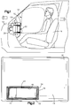
- a vehicle occupant restraint system 10 embodying the present invention is illustrated in Fig. 1.
- the vehicle occupant restraint system 10 is in a vehicle having a passenger seat 15.
- the vehicle has a forward direction of travel indicated by arrow A and a rearward direction of travel indicated by arrow B.
- the passenger seat 15 has an inboard side (seen in Fig. 1) and an outboard side located adjacent the vehicle door.
- the vehicle occupant restraint system 10 includes an inflatable air bag 12 for protecting an occupant seated in the passenger seat 15.
- the air bag 12 When the vehicle is involved in a collision, the air bag 12 is inflated from a folded, collapsed condition to an expanded condition by a rapid flow of inflation fluid from an inflation fluid source, such as an inflator 20.
- an inflation fluid source such as an inflator 20.
- the air bag 12 When the air bag 12 is in the expanded condition (illustrated in dashed lines in Fig. 1), it restrains movement of an occupant seated in the passenger seat 15 and prevents the occupant from violently striking parts of the vehicle interior during a collision. The air bag 12 then quickly collapses so that the occupant is free to exit from the vehicle.
- the air bag 12 includes a main body portion 14 and a neck portion 16 which is sewn to the main body portion 14 in a known manner.
- the neck portion 16 is not centered on the main body portion 14 as can be seen in Fig. 2.
- the neck portion 16 is offset toward the outboard side of the passenger seat 15 (toward the vehicle door) from the center of the air bag 12.
- the neck portion 16 is wrapped around a ring 29 and is secured to a rigid metal reaction canister 24 in a known manner, such as by fasteners (not shown) which extend through openings in the reaction canister 24, the material of the air bag 12, and the ring 29.
- the reaction canister 24 has walls which define an interior chamber 25 in which the folded air bag 12 is stored.
- the reaction canister 24 is located in the instrument panel 13 (Fig. 1) of the vehicle. Although the reaction canister 24 is shown as a separate structure located in the instrument panel 13, the reaction canister could alternatively be defined by surfaces of the instrument panel itself.
- the inflator 20 illustrated is of the augment type.
- the inflator 20 includes a pressurized gas stored in a storage chamber, and an ignitable material which, when ignited, heats the stored gas. The pressure of the gas thus increases as the gas is heated. The pressurized gas in the storage chamber of the inflator 20 is then released to inflate the air bag 12.
- the augment inflator 20 shown in Fig. 9 has a body portion 21 in which the gas is stored and a plurality of nozzle openings 23 disposed at one end of the body portion 21.
- the augment inflator 20 is oriented within the reaction canister 24 such that the nozzle openings 23 are located closer to the outboard side of the passenger seat 15 than the inboard side of the passenger seat 15.
- Flow of inflation fluid from the augment inflator 20 causes the air bag 12 to inflate into the passenger compartment of the vehicle.
- the augment inflator 20 is actuated in response to a signal from a vehicle deceleration sensor (not shown) indicative of the occurrence of a vehicle collision.
- the vehicle occupant restraint system 10 comprises a deflector panel 50, as shown in Figs. 1-3 and 9.
- the deflector panel 50 is attached to the neck portion 16 of the air bag 12 in the vicinity of the location at which the neck portion 16 is sewn to the main body portion 14 of the air bag 12.
- the deflector panel 50 is sewn to both the neck portion 16 and the main body portion 14 of the air bag 12.
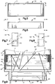
- the deflector panel 50 is formed from two fabric panels 40 as shown in Fig. 4.
- each of the panels 40 is made of 420 denier nylon 6/6.
- each panel 40 is flat and has a major side surface 39. Each panel 40 is punched with a number of holes, notches, and slits. As shown in Fig. 4, the panel 40 is provided with a first pair of triangular notches 41, a second pair of rectangular notches 42, a third pair of triangular notches 43, a fourth pair of rectangular notches 44, a central opening 45, a first slit 46, a second slit 47, a third slit 48, and a fourth slit 49. The first and second slits 46 and 47 and the first and second pairs of notches 41 and 42 are located adjacent one end of the panel 40.
- the third and fourth slits 48 and 49 and the third and fourth pairs of notches 43 and 44 are located adjacent the opposite end of the panel 40. Between them, the first and second slits 46 and 47 define a first end flap 55. Likewise, the third and fourth slits 48 and 49 define between them a second end flap 57.
- two panels 40 of Fig. 4 are located adjacent to each other so that one panel overlies the other panel. The two panels 40 are then folded and secured together to form the deflector panel 50.
- the assembled deflector panel 50 resembles a box with an open top.
- the two panels 40 are manipulated and folded in the vicinity of the first slit 46 so that the first pair of triangular notches 41 align with and overlie each other.
- the two panels 40 are manipulated and folded in the vicinity of the second slit 47 so that the second pair of rectangular notches 42 align with and overlie each other.
- a first line of single needle stitches 51 and a second line of single needle stitches 52 are sewn along the end flap 55.
- the stitch lines 51 and 52 secure the end flap 55 to the overlying layers of material from the portions of the panels 40 which are separated from the end flap 55 by the first and second slits 46 and 47.
- the two panels 40 are manipulated and folded in the vicinity of the third slit 48 so that the third pair of triangular notches 43 align with and overlie each other.
- the two panels 40 are manipulated and folded in the vicinity of the fourth slit 49 so that the fourth pair of rectangular notches 44 align with and overlie each other.
- a third line of single needle stitches 53 and a fourth line of single needle stitches 54 are sewn along the end flap 57.
- the stitch lines 53 and 54 secure the end flap 57 to the overlying layers of material from the portions of the panels 40 which are separated from the end flap 57 by the third and fourth slits 48 and 49.
- the opening 45 is in the bottom of the box-like structure.
- the deflector panel 50 has a first deflecting surface 71 located at one end of the opening 45 and a second deflecting surface 72 located at an opposite end of the opening 45.
- the opening 45 and the first and second deflecting surfaces 71, 72 lie in substantially the same plane.
- the first and second deflecting surfaces 71, 72 are portions of the major side surface 39 and face toward the nozzle openings 23 in the inflator 20.
- the first deflecting surface 71 has an area which is greater than the area of the second deflecting surface 72.
- the first and second deflecting surfaces 71, 72 are coated with silicon to resist abrasion and to withstand high heat.
- the deflector panel 50 is then sewn to the main body portion 14 of the air bag 12 and the neck portion 16 of the air bag 12, as best shown in Figs. 3 and 9. Specifically, the deflector panel 50 is sewn to the neck portion 16 of the air bag 12 using a line of single needle stitches 61 around the entire perimeter of the opening in the neck portion 16 and the main body portion 14 of the air bag 12. Alternatively, the deflector panel 50 may be sewn to the neck portion 16 and the main body portion 14 of the air bag 12 using a line of double needle stitches (not shown) around the entire perimeter of the opening in the neck portion 16 and the main body portion 14 of the air bag 12.
- the deflector panel 50 is offset from the center of the air bag 12 and is located more toward the outboard side of the passenger seat 15.
- the first deflecting surface 71 is located toward the outboard side of the passenger seat 15 and the second deflecting surface 72 is located toward the inboard side of the passenger seat 15.
- the outboard side of the passenger seat 15 is at the left side of Fig. 2 and the inboard side of the passenger seat 15 is at the right side of Fig. 2.
- a portion of the inflation fluid flows from the nozzle openings 23 directly through the opening 45 and into the main body portion 14 of the air bag 12, as depicted by arrows 73 in Fig. 9. Also, a portion of the inflation fluid flows from the nozzle openings 23 toward the first deflecting surface 71 of the deflector panel 50, as depicted by arrow 75 in Fig. 9. This portion of the inflation fluid flow is reflected off of the first deflecting surface 71. The reflected inflation fluid flow off the first deflecting surface 71 is depicted by arrow 76 in Fig. 9.
- the reflected inflation fluid flow depicted by arrow 76 is then redirected toward the opening 45 in the deflector panel 50 into the interior of the air bag 12 to inflate the air bag 12.
- This redirected inflation fluid flow is depicted by arrow 77 in Fig. 9.
- the reflected inflation fluid flow (depicted by arrow 76) is redirected as inflation fluid flow to the opening 45 in the deflector panel 50 (depicted by arrow 77) by the body 21 of the augment inflator 20 and also by the fluid pressure gradient developed as a result of the augment inflator 20 being actuated.
- a portion of the inflation fluid flows from the nozzle openings 23 at the one end of the inflator body 21 toward the opposite end of the inflator body 21, as depicted by arrow 78 in Fig. 9.
- This portion of the inflation fluid flow is reflected off a surface 85 on the reaction canister 24.
- the reflected inflation fluid flow off of the surface 85 is depicted by arrow 79 in Fig. 9.
- the reflected inflation fluid flow depicted by arrow 79 is redirected toward the opening 45 in the deflector panel 50 into the interior of the air bag 12 to inflate the air bag 12.
- Some of the inflation fluid flow depicted by arrow 79 in Fig. 9 may be reflected off the second deflecting surface 72 of the deflector panel 50 and then redirected toward the opening 45 in the same way as explained above with regard to the first deflecting surface 71 of the deflector panel 50.
- An advantage of using a deflector panel 50 constructed in accordance with the present invention is that the inflation fluid flow into the interior of the air bag 12 is better distributed than if the deflector panel 50 did not exist.
- the inflation fluid flow into the interior of the air bag 12 is better distributed because the deflector panel 50 is offset more toward the outboard side of the passenger seat 15 with the relatively larger first deflecting surface 71 being located more toward the outboard side of the passenger seat 15. Since the first deflecting surface 71 is relatively larger than the second deflecting surface 72 and is located more toward the outboard side of the passenger seat 15, the inflation fluid flow from the augment inflator 20 is directed toward the center of the interior of the air bag 12. When the inflation fluid flow into the interior of the air bag 12 is more central, the trajectory of the air bag 12 while inflating is more central.
Landscapes
- Engineering & Computer Science (AREA)
- Mechanical Engineering (AREA)
- Physics & Mathematics (AREA)
- Fluid Mechanics (AREA)
- Air Bags (AREA)
- Shaping By String And By Release Of Stress In Plastics And The Like (AREA)
Applications Claiming Priority (2)
| Application Number | Priority Date | Filing Date | Title |
|---|---|---|---|
| US293675 | 1994-08-19 | ||
| US08/293,675 US5487560A (en) | 1994-08-19 | 1994-08-19 | Apparatus for controlling flow of inflation fluid into an air bag |
Publications (2)
| Publication Number | Publication Date |
|---|---|
| EP0698533A1 true EP0698533A1 (de) | 1996-02-28 |
| EP0698533B1 EP0698533B1 (de) | 1998-11-25 |
Family
ID=23130066
Family Applications (1)
| Application Number | Title | Priority Date | Filing Date |
|---|---|---|---|
| EP95111612A Expired - Lifetime EP0698533B1 (de) | 1994-08-19 | 1995-07-24 | Regeldurchlass für das Inflatorgas eines Gaskissens |
Country Status (10)
| Country | Link |
|---|---|
| US (1) | US5487560A (de) |
| EP (1) | EP0698533B1 (de) |
| JP (1) | JP2863720B2 (de) |
| KR (1) | KR0183179B1 (de) |
| AT (1) | ATE173689T1 (de) |
| CA (1) | CA2152430C (de) |
| CZ (1) | CZ286355B6 (de) |
| DE (1) | DE69506192T2 (de) |
| NO (1) | NO953259L (de) |
| PL (1) | PL178205B1 (de) |
Cited By (2)
| Publication number | Priority date | Publication date | Assignee | Title |
|---|---|---|---|---|
| EP0800963A1 (de) * | 1996-04-12 | 1997-10-15 | TRW Occupant Restraint Systems GmbH | Gassack |
| EP0992403A2 (de) * | 1998-09-21 | 2000-04-12 | TRW Occupant Restraint Systems GmbH & Co. KG | Gewebeteil zur Anordnung im Inneren eines Gassacks eines Fahrzeuginsassen-Rückhaltesystems |
Families Citing this family (6)
| Publication number | Priority date | Publication date | Assignee | Title |
|---|---|---|---|---|
| US5564739A (en) * | 1995-12-07 | 1996-10-15 | Takata, Inc. | Side impact airbag module with soft cover |
| US5833265A (en) * | 1997-02-21 | 1998-11-10 | Takata, Inc. | Airbag with excursion restrictors |
| KR100326138B1 (ko) * | 1999-08-19 | 2002-02-27 | 홍용환 | 고전한옥의 공포(控包)성형용 금형의 제조방법 및 그 금형에 의한 공포성형 방법 |
| US6176512B1 (en) | 1999-10-21 | 2001-01-23 | Trw Vehicle Safety Systems Inc. | Apparatus for directing the flow of inflation fluid into an air bag |
| JP6314878B2 (ja) * | 2015-03-06 | 2018-04-25 | 豊田合成株式会社 | エアバッグ用ケース |
| KR102224496B1 (ko) * | 2018-06-14 | 2021-03-05 | 오승훈 | 선수측에 부력체가 결합된 김채취선 및 그 제작방법 |
Citations (5)
| Publication number | Priority date | Publication date | Assignee | Title |
|---|---|---|---|---|
| EP0422840A2 (de) * | 1989-10-10 | 1991-04-17 | Ford Motor Company Limited | Aufblasbare Insassenrückhaltevorrichtung für Kraftfahrzeug |
| US5160164A (en) * | 1991-06-05 | 1992-11-03 | Trw Vehicle Safety Systems Inc. | Gas deflection device for an air bag assembly |
| DE9408908U1 (de) * | 1994-05-31 | 1994-11-17 | Trw Repa Gmbh | Gassack-Schutzvorrichtung |
| EP0626295A1 (de) * | 1993-05-24 | 1994-11-30 | Morton International, Inc. | Behandlung für Aufblasgas in einem aufblasbaren Rückhaltesystem |
| DE4442118A1 (de) * | 1993-11-26 | 1995-06-01 | Toyo Tire & Rubber Co | Airbag zur Verwendung in einem Fahrzeuginsassen-Rückhaltesystem |
Family Cites Families (15)
| Publication number | Priority date | Publication date | Assignee | Title |
|---|---|---|---|---|
| US3614127A (en) * | 1969-10-20 | 1971-10-19 | Ford Motor Co | Variable pressure air bag restraint device |
| US3784223A (en) * | 1971-06-10 | 1974-01-08 | Eaton Corp | Safety apparatus |
| US4265468A (en) * | 1979-07-03 | 1981-05-05 | General Motors Corporation | Inflatable restraint system |
| US4262931A (en) * | 1979-09-18 | 1981-04-21 | Ford Motor Company | Air bag restraint system |
| JPH0534285Y2 (de) * | 1987-02-05 | 1993-08-31 | ||
| JPH081155Y2 (ja) * | 1987-12-24 | 1996-01-17 | 日産自動車株式会社 | 車両用エアバッグ装置 |
| JPH0651458B2 (ja) * | 1989-10-23 | 1994-07-06 | 池田物産株式会社 | エアバッグ装置 |
| US5033772A (en) * | 1990-01-29 | 1991-07-23 | Allied-Signal Inc. | Hybrid inflator |
| CA2044378A1 (en) * | 1990-10-02 | 1992-04-03 | Mitsuo Matsumoto | Shock-absorbing air bag |
| US5236740A (en) * | 1991-04-26 | 1993-08-17 | National Center For Manufacturing Sciences | Methods for coating adherent diamond films on cemented tungsten carbide substrates |
| US5226671A (en) * | 1991-10-17 | 1993-07-13 | Trw Inc. | Air bag structure and method of forming |
| JPH05116583A (ja) * | 1991-10-24 | 1993-05-14 | Toyota Motor Corp | ベンチシート対応型助手席用エアバツグ装置 |
| US5340147A (en) * | 1991-12-19 | 1994-08-23 | Alliedsignal Inc. | Air bag inflator assembly |
| JP2985466B2 (ja) * | 1992-01-21 | 1999-11-29 | 日産自動車株式会社 | 自動車のエアバッグ装置 |
| JP3074942B2 (ja) * | 1992-07-03 | 2000-08-07 | タカタ株式会社 | 助手席用エアバッグ装置におけるエアバッグ取付構造 |
-
1994
- 1994-08-19 US US08/293,675 patent/US5487560A/en not_active Expired - Lifetime
-
1995
- 1995-06-22 CA CA002152430A patent/CA2152430C/en not_active Expired - Fee Related
- 1995-07-24 EP EP95111612A patent/EP0698533B1/de not_active Expired - Lifetime
- 1995-07-24 AT AT95111612T patent/ATE173689T1/de active
- 1995-07-24 DE DE69506192T patent/DE69506192T2/de not_active Expired - Fee Related
- 1995-07-25 KR KR1019950022045A patent/KR0183179B1/ko not_active IP Right Cessation
- 1995-08-07 JP JP7201044A patent/JP2863720B2/ja not_active Expired - Fee Related
- 1995-08-17 CZ CZ19952109A patent/CZ286355B6/cs not_active IP Right Cessation
- 1995-08-18 NO NO953259A patent/NO953259L/no not_active Application Discontinuation
- 1995-08-18 PL PL95310068A patent/PL178205B1/pl unknown
Patent Citations (5)
| Publication number | Priority date | Publication date | Assignee | Title |
|---|---|---|---|---|
| EP0422840A2 (de) * | 1989-10-10 | 1991-04-17 | Ford Motor Company Limited | Aufblasbare Insassenrückhaltevorrichtung für Kraftfahrzeug |
| US5160164A (en) * | 1991-06-05 | 1992-11-03 | Trw Vehicle Safety Systems Inc. | Gas deflection device for an air bag assembly |
| EP0626295A1 (de) * | 1993-05-24 | 1994-11-30 | Morton International, Inc. | Behandlung für Aufblasgas in einem aufblasbaren Rückhaltesystem |
| DE4442118A1 (de) * | 1993-11-26 | 1995-06-01 | Toyo Tire & Rubber Co | Airbag zur Verwendung in einem Fahrzeuginsassen-Rückhaltesystem |
| DE9408908U1 (de) * | 1994-05-31 | 1994-11-17 | Trw Repa Gmbh | Gassack-Schutzvorrichtung |
Cited By (5)
| Publication number | Priority date | Publication date | Assignee | Title |
|---|---|---|---|---|
| EP0800963A1 (de) * | 1996-04-12 | 1997-10-15 | TRW Occupant Restraint Systems GmbH | Gassack |
| US5918902A (en) * | 1996-04-12 | 1999-07-06 | Trw Occupant Restraint Systems Gmbh | Gas bag |
| EP0992403A2 (de) * | 1998-09-21 | 2000-04-12 | TRW Occupant Restraint Systems GmbH & Co. KG | Gewebeteil zur Anordnung im Inneren eines Gassacks eines Fahrzeuginsassen-Rückhaltesystems |
| EP0992403A3 (de) * | 1998-09-21 | 2000-04-19 | TRW Occupant Restraint Systems GmbH & Co. KG | Gewebeteil zur Anordnung im Inneren eines Gassacks eines Fahrzeuginsassen-Rückhaltesystems |
| US6260881B1 (en) | 1998-09-21 | 2001-07-17 | Trw Occupant Restraint Gmbh & Co. Kg | Fabric part for arranging in the interior of a gas bag of a vehicle occupant restraint system |
Also Published As
| Publication number | Publication date |
|---|---|
| CZ286355B6 (cs) | 2000-03-15 |
| KR0183179B1 (ko) | 1999-05-01 |
| CA2152430A1 (en) | 1996-02-20 |
| ATE173689T1 (de) | 1998-12-15 |
| PL310068A1 (en) | 1996-03-04 |
| JPH0867229A (ja) | 1996-03-12 |
| EP0698533B1 (de) | 1998-11-25 |
| PL178205B1 (pl) | 2000-03-31 |
| JP2863720B2 (ja) | 1999-03-03 |
| NO953259L (no) | 1996-02-20 |
| US5487560A (en) | 1996-01-30 |
| NO953259D0 (no) | 1995-08-18 |
| KR960007308A (ko) | 1996-03-22 |
| DE69506192D1 (de) | 1999-01-07 |
| DE69506192T2 (de) | 1999-06-24 |
| CZ210995A3 (en) | 1996-03-13 |
| CA2152430C (en) | 1999-01-19 |
Similar Documents
| Publication | Publication Date | Title |
|---|---|---|
| EP1117569B1 (de) | Airbag mit umlenkvorrichtung und einer in ihren volumen expandierbaren kammer | |
| JP2761350B2 (ja) | 自動推進式エアバッグクッション用の装置、および車両用の膨張可能な乗員拘束装置 | |
| US5405166A (en) | Air bag with inflation limiter | |
| US5454595A (en) | Hidden volume cushion | |
| US3938826A (en) | Aspirated vehicle occupant restraint system | |
| EP0586131B1 (de) | Bänder mit Reissnähten für ein Luftkissen | |
| EP1879773B1 (de) | Vorhangairbaganordnung | |
| US5593179A (en) | Air bag device for vehicle | |
| EP0422840B1 (de) | Aufblasbare Insassenrückhaltevorrichtung für Kraftfahrzeug | |
| EP1354771B1 (de) | Insassenbeinschutzvorrichtung | |
| EP0061828B1 (de) | Niedrig angebrachter und leicht montierbarer Luftsack als passives Rückhaltesystem | |
| US5207450A (en) | Aspirated air cushion restraint system | |
| JPH0752746A (ja) | 乗用車用エアバッグクッション | |
| JPH068783A (ja) | 自動車用エアバッグのガイドシュート | |
| JP2003528758A (ja) | エアバッグシステム | |
| US5634659A (en) | Air bag with a vent | |
| US5487560A (en) | Apparatus for controlling flow of inflation fluid into an air bag | |
| JPH07329694A (ja) | エアバッグの内圧調節装置 | |
| US6176512B1 (en) | Apparatus for directing the flow of inflation fluid into an air bag | |
| US6145872A (en) | Airbag cushion attachment | |
| US20070222194A1 (en) | Air bag module with a shield | |
| JPH02283545A (ja) | エアバッグ装置 | |
| US6227566B1 (en) | Airbag device with inflator | |
| JPH05116583A (ja) | ベンチシート対応型助手席用エアバツグ装置 | |
| JPH0930353A (ja) | エアバッグ装置 |
Legal Events
| Date | Code | Title | Description |
|---|---|---|---|
| PUAI | Public reference made under article 153(3) epc to a published international application that has entered the european phase |
Free format text: ORIGINAL CODE: 0009012 |
|
| 17P | Request for examination filed |
Effective date: 19950724 |
|
| AK | Designated contracting states |
Kind code of ref document: A1 Designated state(s): AT BE CH DE DK ES FR GB GR IE IT LI LU MC NL PT SE |
|
| 17Q | First examination report despatched |
Effective date: 19961203 |
|
| GRAG | Despatch of communication of intention to grant |
Free format text: ORIGINAL CODE: EPIDOS AGRA |
|
| GRAG | Despatch of communication of intention to grant |
Free format text: ORIGINAL CODE: EPIDOS AGRA |
|
| GRAH | Despatch of communication of intention to grant a patent |
Free format text: ORIGINAL CODE: EPIDOS IGRA |
|
| GRAH | Despatch of communication of intention to grant a patent |
Free format text: ORIGINAL CODE: EPIDOS IGRA |
|
| GRAA | (expected) grant |
Free format text: ORIGINAL CODE: 0009210 |
|
| AK | Designated contracting states |
Kind code of ref document: B1 Designated state(s): AT BE CH DE DK ES FR GB GR IE IT LI LU MC NL PT SE |
|
| PG25 | Lapsed in a contracting state [announced via postgrant information from national office to epo] |
Ref country code: SE Free format text: THE PATENT HAS BEEN ANNULLED BY A DECISION OF A NATIONAL AUTHORITY Effective date: 19981125 Ref country code: NL Free format text: LAPSE BECAUSE OF FAILURE TO SUBMIT A TRANSLATION OF THE DESCRIPTION OR TO PAY THE FEE WITHIN THE PRESCRIBED TIME-LIMIT Effective date: 19981125 Ref country code: LI Free format text: LAPSE BECAUSE OF FAILURE TO SUBMIT A TRANSLATION OF THE DESCRIPTION OR TO PAY THE FEE WITHIN THE PRESCRIBED TIME-LIMIT Effective date: 19981125 Ref country code: GR Free format text: LAPSE BECAUSE OF NON-PAYMENT OF DUE FEES Effective date: 19981125 Ref country code: ES Free format text: THE PATENT HAS BEEN ANNULLED BY A DECISION OF A NATIONAL AUTHORITY Effective date: 19981125 Ref country code: CH Free format text: LAPSE BECAUSE OF FAILURE TO SUBMIT A TRANSLATION OF THE DESCRIPTION OR TO PAY THE FEE WITHIN THE PRESCRIBED TIME-LIMIT Effective date: 19981125 Ref country code: BE Free format text: LAPSE BECAUSE OF FAILURE TO SUBMIT A TRANSLATION OF THE DESCRIPTION OR TO PAY THE FEE WITHIN THE PRESCRIBED TIME-LIMIT Effective date: 19981125 Ref country code: AT Free format text: LAPSE BECAUSE OF FAILURE TO SUBMIT A TRANSLATION OF THE DESCRIPTION OR TO PAY THE FEE WITHIN THE PRESCRIBED TIME-LIMIT Effective date: 19981125 |
|
| REF | Corresponds to: |
Ref document number: 173689 Country of ref document: AT Date of ref document: 19981215 Kind code of ref document: T |
|
| REG | Reference to a national code |
Ref country code: CH Ref legal event code: EP |
|
| REF | Corresponds to: |
Ref document number: 69506192 Country of ref document: DE Date of ref document: 19990107 |
|
| REG | Reference to a national code |
Ref country code: IE Ref legal event code: FG4D |
|
| ET | Fr: translation filed | ||
| PG25 | Lapsed in a contracting state [announced via postgrant information from national office to epo] |
Ref country code: PT Free format text: LAPSE BECAUSE OF FAILURE TO SUBMIT A TRANSLATION OF THE DESCRIPTION OR TO PAY THE FEE WITHIN THE PRESCRIBED TIME-LIMIT Effective date: 19990225 Ref country code: DK Free format text: LAPSE BECAUSE OF FAILURE TO SUBMIT A TRANSLATION OF THE DESCRIPTION OR TO PAY THE FEE WITHIN THE PRESCRIBED TIME-LIMIT Effective date: 19990225 |
|
| NLV1 | Nl: lapsed or annulled due to failure to fulfill the requirements of art. 29p and 29m of the patents act | ||
| REG | Reference to a national code |
Ref country code: CH Ref legal event code: PL |
|
| PGFP | Annual fee paid to national office [announced via postgrant information from national office to epo] |
Ref country code: FR Payment date: 19990707 Year of fee payment: 5 |
|
| PG25 | Lapsed in a contracting state [announced via postgrant information from national office to epo] |
Ref country code: LU Free format text: LAPSE BECAUSE OF NON-PAYMENT OF DUE FEES Effective date: 19990724 Ref country code: IE Free format text: LAPSE BECAUSE OF NON-PAYMENT OF DUE FEES Effective date: 19990724 Ref country code: GB Free format text: LAPSE BECAUSE OF NON-PAYMENT OF DUE FEES Effective date: 19990724 |
|
| PLBE | No opposition filed within time limit |
Free format text: ORIGINAL CODE: 0009261 |
|
| STAA | Information on the status of an ep patent application or granted ep patent |
Free format text: STATUS: NO OPPOSITION FILED WITHIN TIME LIMIT |
|
| 26N | No opposition filed | ||
| PG25 | Lapsed in a contracting state [announced via postgrant information from national office to epo] |
Ref country code: MC Free format text: LAPSE BECAUSE OF NON-PAYMENT OF DUE FEES Effective date: 20000131 |
|
| GBPC | Gb: european patent ceased through non-payment of renewal fee |
Effective date: 19990724 |
|
| REG | Reference to a national code |
Ref country code: IE Ref legal event code: MM4A |
|
| PG25 | Lapsed in a contracting state [announced via postgrant information from national office to epo] |
Ref country code: FR Free format text: LAPSE BECAUSE OF NON-PAYMENT OF DUE FEES Effective date: 20010330 |
|
| REG | Reference to a national code |
Ref country code: FR Ref legal event code: ST |
|
| PG25 | Lapsed in a contracting state [announced via postgrant information from national office to epo] |
Ref country code: IT Free format text: LAPSE BECAUSE OF NON-PAYMENT OF DUE FEES;WARNING: LAPSES OF ITALIAN PATENTS WITH EFFECTIVE DATE BEFORE 2007 MAY HAVE OCCURRED AT ANY TIME BEFORE 2007. THE CORRECT EFFECTIVE DATE MAY BE DIFFERENT FROM THE ONE RECORDED. Effective date: 20050724 |
|
| PGFP | Annual fee paid to national office [announced via postgrant information from national office to epo] |
Ref country code: DE Payment date: 20070731 Year of fee payment: 13 |
|
| PG25 | Lapsed in a contracting state [announced via postgrant information from national office to epo] |
Ref country code: DE Free format text: LAPSE BECAUSE OF NON-PAYMENT OF DUE FEES Effective date: 20090203 |