EP0698144B1 - Crossing nose - Google Patents
Crossing nose Download PDFInfo
- Publication number
- EP0698144B1 EP0698144B1 EP94917581A EP94917581A EP0698144B1 EP 0698144 B1 EP0698144 B1 EP 0698144B1 EP 94917581 A EP94917581 A EP 94917581A EP 94917581 A EP94917581 A EP 94917581A EP 0698144 B1 EP0698144 B1 EP 0698144B1
- Authority
- EP
- European Patent Office
- Prior art keywords
- frog tip
- frog
- tip
- roller
- roller element
- Prior art date
- Legal status (The legal status is an assumption and is not a legal conclusion. Google has not performed a legal analysis and makes no representation as to the accuracy of the status listed.)
- Expired - Lifetime
Links
- 239000000758 substrate Substances 0.000 abstract 1
- 238000013016 damping Methods 0.000 description 8
- 239000000725 suspension Substances 0.000 description 4
- 238000006073 displacement reaction Methods 0.000 description 3
- 238000012423 maintenance Methods 0.000 description 3
- 230000003993 interaction Effects 0.000 description 2
- 239000000314 lubricant Substances 0.000 description 2
- 238000005096 rolling process Methods 0.000 description 2
- 210000002105 tongue Anatomy 0.000 description 2
- 238000010276 construction Methods 0.000 description 1
- 230000000694 effects Effects 0.000 description 1
- 229920001971 elastomer Polymers 0.000 description 1
- 239000000806 elastomer Substances 0.000 description 1
- 238000003912 environmental pollution Methods 0.000 description 1
- 230000000763 evoking effect Effects 0.000 description 1
- 238000007689 inspection Methods 0.000 description 1
- 238000005461 lubrication Methods 0.000 description 1
- 239000000463 material Substances 0.000 description 1
- 230000000284 resting effect Effects 0.000 description 1
Images


Classifications
-
- E—FIXED CONSTRUCTIONS
- E01—CONSTRUCTION OF ROADS, RAILWAYS, OR BRIDGES
- E01B—PERMANENT WAY; PERMANENT-WAY TOOLS; MACHINES FOR MAKING RAILWAYS OF ALL KINDS
- E01B7/00—Switches; Crossings
- E01B7/10—Frogs
- E01B7/14—Frogs with movable parts
-
- E—FIXED CONSTRUCTIONS
- E01—CONSTRUCTION OF ROADS, RAILWAYS, OR BRIDGES
- E01B—PERMANENT WAY; PERMANENT-WAY TOOLS; MACHINES FOR MAKING RAILWAYS OF ALL KINDS
- E01B7/00—Switches; Crossings
- E01B7/10—Frogs
- E01B7/12—Fixed frogs made of one part or composite
Definitions
- the invention relates to a frog tip, with its underside between Wing rails are movably arranged on a base such as a sliding chair and at one of the wing rails adjacent position or end position preferably by means of at least one locking clip received guided by a locking part can be locked.
- the well-known movable centerpiece tips are on a sliding chair between their end positions moved back and forth to be locked when they are on a wing rail. It is due to the sliding on the sliding chair Requires frequent inspection and maintenance. Especially lubrication work is often required, the lubricant itself becoming one Can cause environmental pollution; see. "Die Eisenbahnschiene”, published by Wilhelm Ernst & Sohn, Berlin, Kunststoff, Düsseldorf, 1977, pages 336 and 337.
- the present invention is based on the problem of a frog tip type described in the beginning so that a reduction in maintenance is possible without constructively complex measures or special materials are required for the pad and the centerpiece tip.
- the object is achieved in that the frog tip in their positions on the wing rails supported by the pad and between the positions on the wing rails is spaced from the base.
- the frog tip only in the end positions, So in the locked states, on which the support is supported like a sliding chair, whereas when moving from one to the other end position one Distance to the document is made. This results in a reduction in maintenance while saving lubricants.
- a further development of the invention provides that the foot of the frog tip directly or indirectly an element that runs along or roughly has projection extending along the central axis of the frog tip, and that the element interacts with a roller element, the central axis of which is approximately or approximately runs in a plane of symmetry running between the wing rails. It can the element on the roller element side have a surface that consists of two outer concaves extending sections and a middle preferably plateau-like section is composed, which forms the projection.
- the centerpiece tip is then raised and thus spaced from the base when the projection or its flanks over the Roller element slides.
- the radii of curvature of the outer portions at least in the area adjacent to the central section, or approximately the radius of curvature correspond to the roller element.
- the roller element is preferably different on at least two spring elements Characteristic curves is supported, with the one spring element essentially constant rigidity and the other spring element has a variable rigidity and the spring elements are mechanically coupled to one another in such a way that when Centerpiece loaded roller element each spring element an effective Has travel.
- the invention is characterized in that the Spring elements extend on opposite sides of a carrier element and over a connecting element such as a screw can be adjusted in such a way that the distance between them can be adjusted that the damping effecting spring element with the variable rigidity the side of the carrier element facing away from the frog tip runs that the Spring element with the variable rigidity in such a way when the roller element is not loaded is attracted by the connecting element against the support member that a Spring action is excluded or essentially excluded, and that at loaded roller element of each of the spring elements usual additional loading and Has relief of the roller element receiving spring travel lengths.
- the spring elements are, on the one hand, a suspension spring and, on the other hand a damping spring, at least the latter, but preferably both elastomer springs are.
- the damping spring has a rigidity that is preferably is ten times smaller than that of the suspension spring.
- the damping spring provides suspension and thus damping in both directions, so that the tip of the frog hits a surface how sliding chair is excluded.
- the damping spring quick vibration reduction in the centerpiece tip itself evoked.
- the working position of the roller elements is determined by the rigidity of the suspension spring, that is, the level at which the centerpiece tip rests.
- the element having the projection is directly or indirectly from the Centerpiece tip, this is preferably a cuboid Section of locking clip receptacles connecting the frog tip Brackets formed.
- the centerpiece tip rolls on the roller elements by the measures according to the invention when moving off, with a pivoting during movement from one end position to the other end position with the result that the Centerpiece tip is spaced from the base.
- the frog tip lies against one of the wing rails Position on the roller element close to the wing rail and touches with the other roller element on its longitudinal edge facing away from the wing rail.
- Another proposal of the invention provides that the locking clip preferably in the longitudinal direction of the frog tip slidably from a locking clip receptacle connected to the frog tip assumes that at least one roller element extends from the closure clip, which of one passing through the closure piece, perpendicular or almost perpendicular to Centerpiece longitudinal axis displaceable sliding element is detectable, and that that Roller element on a parallel or approximately parallel to the direction of displacement Sliding element extending support is supported, which in turn is stationary for Closure piece is arranged or starts from this.
- Centerpiece tip the roller element in one of the sliding element and the support at least partially limited recording, so that a safe concern the centerpiece tip is guaranteed on one of the wing rails.
- the tip of the frog is raised from the base. that when moving the frog tip, the roller element of a ramp-shaped Section of the sliding element is detected and raised.
- the roller element itself preferably goes from one below one of the wing rails associated locking rail extending leg of the locking clip out.
- two roller elements extend from the leg and that in each case a roller element is arranged in the end region of the leg.
- each of the roller elements is in sections of the sliding element and the support like career-formed recordings set.
- Locking plate receptacles are attached to the frog tip (10) via connecting plates (16) and (18) (20) and (22), each of which is parallel to the Axes (24) and (26) rotating clamps running along the longitudinal axis of the frog tip (28) and (30) go out, push through the locking pieces (32) and (34) by the Wing rails (12) and (14) associated closure rails (36) and (38) or other fasteners.
- the brackets (28) and (30) are also in Movable in the longitudinal direction of the locking rails (36).
- a slide (40) is also received from the closure pieces (32) and (34), through which the locking clips (28) and (30) are grasped around the frog tip (10) to move from one end position to the other and at the same time during of sliding off the sliding chair. Also goes from the closures (32), (34) a support (42) to be designated as a career.
- the brackets (28) and (30) each have one below the locking rail (36) or (38) extending leg (44) or (46), which rolls in its end region (48), (50) or (52), (54), which on the one hand roll along the track (42) and on the other hand can be detected by the slide (40).
- the slide (40) preferably consists of two legs running parallel to one another there is between which the raceway (42) runs, the roller elements (48) have (50), (52), (54) rolls with different diameters to always have a rolling Ensure movement.
- the slide (40) has channel-like and in opposite Directional receptacles (64), (66) and (68), (70) for the rollers (48) and (50) or (52) and (54), with the channels (64), (66), (68) and (70) each are delimited by lower ramp-shaped flanks which have the reference symbols (72), (74), (76) and (78).
- the raceway (42) has in its outer edge the rollers (48) and (54) adapted Recordings (80) and (82) in which the roller element (48) (Fig. 1) and (54) (Fig. 2) is fixed when the frog tip (10) on the wing rail (12) (Fig. 1) or Wing rail (14) (Fig. 2) rests and is locked.
- the centerpiece tip (10) should be removed from the wing rail (12) and onto the wing rail (14) are created, so the slide (40) in the exemplary embodiments shifted to the right, whereby on the one hand the roller element (45) is released and on the other hand, this is gripped by the slope (72) and into the channel-shaped receptacle (64) is moved. At the same time the leg (44) of the bracket (30) and thus the Centerpiece tip (10) raised.
- the roller (50) slides out out the channel (66), which is said to be inclined, in such a way that at on the wing rail (14) in the position of the frog tip (10) again is lowered and on the documents, not shown, such as sliding chairs that are in front of or are arranged behind the locking devices, rests.
- the roller (50) can then additionally bear against a section (86) of the raceway (42).
- rollers (52) and (54) are of course shifted in the opposite sense and fixed.
- FIGS. 1 and 2 differs from that of FIGS. 1 and 2 in that the lifting of the frog tip (10) is not or not only from the clips (88) and (90) outgoing from the closure clip receptacles (20), (22) takes place, but via a protrusion connected to the frog tip (10) (92) having a cuboid element (94), which has an elastically mounted Roller element (96) interacts in the manner described below.
- an essentially has horizontally extending leg (98) or (100) of the locking clip (88) or (90) only in its end region (102) or (104) facing away from the frog tip (10) Roller element (48) or (54), but in the manner described above with the Slider (40) and the track (42) or sections of this interacts and is set.
- leg (98) or (100) of the locking clip (88) or (90) only in its end region (102) or (104) facing away from the frog tip (10) Roller element (48) or (54), but in the manner described above with the Slider (40) and the track (42) or sections of this interacts and is set.
- FIGS. 1, 2 and 5, 5 in the actual sense represents a detailed representation of FIG. 3.
- the projection (52) extends along the central axis (106) of the frog tip (10).
- the roller element (96) is rotatable about an axis (114) which is parallel to the longitudinal axis the frog tip (10) runs in one between the wing rails (12) and (14) extending symmetry plane (116).
- the areas of the outer adjoining the plateau-like projection (92) Sections (108) and (110) also have curvatures that are approximately the same the curvature of the roller element (96). This causes a rolling sliding of the Surface (108) of the cuboid block (94) on the surface of the roller element (96), which reduces wear.
- the centerpiece tip (10) from the left end position that is from the Wing rail (12) in the position adjacent to the wing rail (14)
- the locking clips (58) and (90) in previously described manner by means of the slide (10) moved from left to right, wherein lifting by the interaction of the roller element (48) with the ramp (72) takes place, and on the other hand, the surface (108) rolls on the roller element (96) such that due to the projection directed away from the frog tip (10) this is done.
- a rocker (118) can be seen by means of which the frog tip (10) is moved from one end position to the other in such a way that only in the End positions are supported on a sliding chair, whereas during the shifting movement a distance from this is ensured.
- the centerpiece tip (10) is in the on the wing rail (12) adjacent position, that is the left end position, which corresponds to FIGS. 1 and 4.
- the bottom of the frog (10) rests with its underside (120) on a roller (122) that of a bar (124) which extends out from a rocker (118) pivotable about an axis (126), namely from the section facing the wing rail (12).
- the line of contact (128) is between Underside (120) of the frog tip (10) and roller element (122) in the support plane the sliding chairs or sections arranged between the rocker (s) (118) this.
- the beam (124) points with respect to the axis of rotation (126) to the roller element (128) symmetrically arranged second roller element (130) on which the Centerpiece tip (10) with its end position locked on the wing rail (12) the wing rail (12) faces away from the longitudinal edge (132).
Landscapes
- Engineering & Computer Science (AREA)
- Mechanical Engineering (AREA)
- Architecture (AREA)
- Civil Engineering (AREA)
- Structural Engineering (AREA)
- Seats For Vehicles (AREA)
- Electrotherapy Devices (AREA)
- Surgical Instruments (AREA)
- Turbine Rotor Nozzle Sealing (AREA)
- Orthopedics, Nursing, And Contraception (AREA)
- Chairs For Special Purposes, Such As Reclining Chairs (AREA)
- Catching Or Destruction (AREA)
- Details Of Garments (AREA)
- Magnetic Heads (AREA)
- Bipolar Transistors (AREA)
- Percussion Or Vibration Massage (AREA)
- Cold Cathode And The Manufacture (AREA)
- Surface Acoustic Wave Elements And Circuit Networks Thereof (AREA)
- Massaging Devices (AREA)
- Materials For Medical Uses (AREA)
- Diaphragms For Electromechanical Transducers (AREA)
- Push-Button Switches (AREA)
- Prostheses (AREA)
- Train Traffic Observation, Control, And Security (AREA)
Abstract
Description
Die Erfindung bezieht sich auf eine Herzstückspitze, die mit ihrer Unterseite zwischen Flügelschienen auf einer Unterlage wie Gleitstuhl beweglich angeordnet ist und bei an einer der Flügelschienen anliegender Stellung bzw. Endstellung vorzugsweise mittels zumindest einer von einem Verschlußteil geführt aufgenommenen Verschlußklammer verriegelbar ist.The invention relates to a frog tip, with its underside between Wing rails are movably arranged on a base such as a sliding chair and at one of the wing rails adjacent position or end position preferably by means of at least one locking clip received guided by a locking part can be locked.
Die bekannten beweglichen Herzstückspitzen werden auf einem Gleitstuhl zwischen ihren Endstellungen hin und her bewegt, um sodann verriegelt zu werden, wenn sie an einer Flügelschiene anliegen. Durch das Verschieben auf dem Gleitstuhl bedingt ist es erforderlich, daß eine häufige Überprüfung und Wartung erforderlich ist. Insbesondere sind häufig Schmierarbeiten erforderlich, wobei der Schmierstoff selbst zu einer Umweltbelastung führen kann; vgl. "Die Eisenbahnschiene", Verlag von Wilhelm Ernst & Sohn, Berlin, München, Düsseldorf, 1977, Seiten 336 und 337.The well-known movable centerpiece tips are on a sliding chair between their end positions moved back and forth to be locked when they are on a wing rail. It is due to the sliding on the sliding chair Requires frequent inspection and maintenance. Especially lubrication work is often required, the lubricant itself becoming one Can cause environmental pollution; see. "Die Eisenbahnschiene", published by Wilhelm Ernst & Sohn, Berlin, Munich, Düsseldorf, 1977, pages 336 and 337.
Der vorliegenden Erfindung liegt das Problem zugrunde, eine Herzstückspitze der eingangs beschriebenen Art so weiterzubilden, daß eine Reduzierung der Wartung möglich ist, ohne daß konstruktiv aufwendige Maßnahmen oder besondere Materialien für Unterlage und Herzstückspitze erforderlich sind.The present invention is based on the problem of a frog tip type described in the beginning so that a reduction in maintenance is possible without constructively complex measures or special materials are required for the pad and the centerpiece tip.
Erfindungsgemäß wird die Aufgabe dadurch gelöst, daß die Herzstückspitze in ihren an den Flügelschienen anliegenden Stellungen auf der Unterlage abgestützt und zwischen den an den Flügelschienen anliegenden Stellungen beabstandet zur Unterlage angeordnet ist. According to the invention the object is achieved in that the frog tip in their positions on the wing rails supported by the pad and between the positions on the wing rails is spaced from the base.
Erfindungsgemäß wird vorgeschlagen, daß die Herzstückspitze nur in den Endstellungen, also in den verriegelten Zuständen, auf der Unterlage wie Gleitstuhl abgestützt ist, wohingegen beim Verschieben von der einen zu der anderen Endstellung eine Beabstandung zu der Unterlage erfolgt. Hieraus resultiert eine Wartungsreduzierung unter gleichzeitiger Einsparung von Schmiermitteln.According to the invention it is proposed that the frog tip only in the end positions, So in the locked states, on which the support is supported like a sliding chair, whereas when moving from one to the other end position one Distance to the document is made. This results in a reduction in maintenance while saving lubricants.
Zwar war es z.B. gemäß der US 2,533,929 bereits nahezu 50 Jahre bekannt, Weichenzungen während ihres Verstellens zu einer Unterlage wie Gleitstuhl zu beabstanden, ohne daß ein entsprechender Vorschlag für Herzstückspitzen zur Anwendung gelangte. Aus der EP 0 495 160 A1 ist ebenfalls ein sich allein auf Zungenschienen beziehender Vorschlag bekannt, um diese beim Verstellen mittels einer Wippe anheben zu können.It was e.g. Already known for almost 50 years according to US 2,533,929, switch tongues during their adjustment to a base such as a sliding chair without a corresponding proposal for centerpiece tips was used. From EP 0 495 160 A1, a proposal relating only to tongue rails is also known, um to be able to lift them when adjusting using a rocker.
Eine Weiterbildung der Erfindung sieht vor, daß fußseitig von der Herzstückspitze mittelbar oder unmittelbar ein Element ausgeht, das einen sich entlang oder in etwa entlang der Mittelachse der Herzstückspitze erstreckenden Vorsprung aufweist, und daß das Element mit einem Rollenelement wechselwirkt, dessen Mittelachse in oder in etwa in einer zwischen den Flügelschienen verlaufenden Symmetrieebene verläuft. Dabei kann das Element rollenelementseitig eine Fläche aufweisen, die aus zwei äußeren konkav verlaufenden Abschnitten und einem mittleren vorzugsweise plateauartigen Abschnitt zusammengesetzt ist, der den Vorsprung bildet.A further development of the invention provides that the foot of the frog tip directly or indirectly an element that runs along or roughly has projection extending along the central axis of the frog tip, and that the element interacts with a roller element, the central axis of which is approximately or approximately runs in a plane of symmetry running between the wing rails. It can the element on the roller element side have a surface that consists of two outer concaves extending sections and a middle preferably plateau-like section is composed, which forms the projection.
Durch das Zusammenwirken der Elemente wird die Herzstückspitze dann angehoben und somit zur Unterlage beabstandet, wenn der Vorsprung bzw. dessen Flanken über das Rollenelement gleitet.Through the interaction of the elements, the centerpiece tip is then raised and thus spaced from the base when the projection or its flanks over the Roller element slides.
Um stoßartige Bewegungen auszuschließen, die zu einem Verschleiß führen könnten, ist des weiteren vorgesehen, daß die Krümmungsradien der äußeren Abschnitte zumindest in dem Bereich der an den mittleren Abschnitt angrenzt, dem oder in etwa dem Krümmungsradius des Rollenelementes entsprechen.To rule out jerky movements that could lead to wear further provided that the radii of curvature of the outer portions at least in the area adjacent to the central section, or approximately the radius of curvature correspond to the roller element.
Selbstverständlich besteht auch die Möglichkeit, das Rollenelement und das von der Herzstückspitze ausgehende Element auszutauschen.Of course, there is also the possibility of the roller element and the Exchanging outgoing element centerpiece tip.
Das Rollenelement ist vorzugsweise auf zumindest zwei Federelementen unterschiedlicher Kennlinien abgestützt ist, wobei das eine Federelement eine im wesentlichen konstante Steifigkeit und das andere Federelement eine veränderliche Steifigkeit aufweist und die Federelemente derart mechanisch miteinander gekoppelt sind, daß bei durch die Herzstückspitze belastetem Rollenelement jedes Federelement einen wirksamen Federweg aufweist. Insbesondere zeichnet sich die Erfindung dadurch aus, daß sich die Federelemente auf gegenüberliegenden Seiten eines Trägerelementes erstrecken und über ein Verbindungselement wie Schraube abstandsveränderbar zueinander einstellbar sind, daß das eine Dämpfung bewirkende Federelement mit der veränderlichen Steifigkeit auf der der Herzstückspitze abgewandten Seite des Trägerelementes verläuft, daß das Federelement mit der veränderlichen Steifigkeit bei unbelastetem Rollenelement derart durch das Verbindungselement gegen das Tragelement angezogen ist, daß eine Federwirkung ausgeschlossen oder im wesentlichen ausgeschlossen ist, und daß bei belastetem Rollenelement jedes der Federelemente übliche zusätzliche Be- und Entlastungen des Rollenelementes aufnehmende Federweglängen aufweist.The roller element is preferably different on at least two spring elements Characteristic curves is supported, with the one spring element essentially constant rigidity and the other spring element has a variable rigidity and the spring elements are mechanically coupled to one another in such a way that when Centerpiece loaded roller element each spring element an effective Has travel. In particular, the invention is characterized in that the Spring elements extend on opposite sides of a carrier element and over a connecting element such as a screw can be adjusted in such a way that the distance between them can be adjusted that the damping effecting spring element with the variable rigidity the side of the carrier element facing away from the frog tip runs that the Spring element with the variable rigidity in such a way when the roller element is not loaded is attracted by the connecting element against the support member that a Spring action is excluded or essentially excluded, and that at loaded roller element of each of the spring elements usual additional loading and Has relief of the roller element receiving spring travel lengths.
Bei den Federelementen handelt es sich einerseits um eine Tragfeder und andererseits um eine Dämpfungsfeder, wobei zumindest letztere, vorzugsweise jedoch beide Elastomerfedern sind. Die Dämpfungsfeder weist dabei eine Steifigkeit auf, die vorzugsweise zehnmal kleiner als die der Tragfeder ist.The spring elements are, on the one hand, a suspension spring and, on the other hand a damping spring, at least the latter, but preferably both elastomer springs are. The damping spring has a rigidity that is preferably is ten times smaller than that of the suspension spring.
Beim Vorspannen der Federelemente, also dann, wenn das Rollenelement nicht belastet ist, wird die Dämpfungsfeder auf Block oder nahezu auf Block eingestellt, um sodann bei durch die Herzstückspitze belastetem Rollenelement in eine Arbeitsstellung zu gelangen (Arbeitspunkt), die es ermöglicht, daß bei üblichen Be- und Entlastungen des Rollenelementes durch auf dieses einwirkender Herzstückspitze der Vorspannungspunkt, also die Blockstellung nicht erreicht wird.When prestressing the spring elements, i.e. when the roller element is not loaded is, the damping spring is set to block or almost to block, then with the roller element loaded by the centerpiece tip into a working position get (working point), which makes it possible that the usual Roller element by the bias point acting on this centerpiece tip, thus the block position is not reached.
Im Arbeitspunkt erfolgt durch die Dämpfungsfeder eine Federung und damit Dämpfung in beiden Richtungen, so daß ein Aufschlagen der Herzstückspitze auf eine Unterlage wie Gleitstuhl ausgeschlossen wird. Gleichzeitig wird aufgrund der Dämpfungseigenschaften der Dämpfungsfeder ein schneller Schwingungsabbau in der Herzstückspitze selbst hervorgerufen. At the operating point, the damping spring provides suspension and thus damping in both directions, so that the tip of the frog hits a surface how sliding chair is excluded. At the same time due to the damping properties the damping spring quick vibration reduction in the centerpiece tip itself evoked.
Durch die Steifigkeit der Tragfeder wird die Arbeitsstellung der Rollenelemente vorgegeben, das heißt das Niveau, auf dem die Herzstückspitze zu ruhen kommt.The working position of the roller elements is determined by the rigidity of the suspension spring, that is, the level at which the centerpiece tip rests.
Sofern das den Vorsprung aufweisende Element mittelbar oder unmittelbar von der Herzstückspitze ausgeht, wird dieses vorzugsweise durch einen quaderförmigen Abschnitt von Verschlußklammeraufnahmen mit der Herzstückspitze verbindenden Halterungen gebildet.Provided that the element having the projection is directly or indirectly from the Centerpiece tip, this is preferably a cuboid Section of locking clip receptacles connecting the frog tip Brackets formed.
Selbstverständlich besteht auch die Möglichkeit, die Herstückspitzenunterseite nur mit einem oder mehrere Rollenelemente wechselwirken zu lassen, um die erfindungsgemäße Lehre zu realisieren.Of course, there is also the option of using the bottom of the tip only to interact with one or more roller elements in order to achieve the invention To realize teaching.
Ein weiterer Lösungsvorschlag sieht vor, daß unterhalb der Herzstückspitze zumindest eine diese abstützende Wippe angeordnet ist, dessen Drehachse in oder in etwa in zwischen den Flügelschienen verlaufender Symmetrieebene liegt. Dabei weist die Wippe einen geradlinigen oder gewinkelten Balken mit symmetrisch zur Drehachse angeordneten und mit der Herzstückspitzenunterseite wechselwirkenden, im Durchmesser gleichgroßen Rollen auf.Another proposed solution provides that below the centerpiece tip at least one rocker supporting this is arranged, the axis of rotation of which is in or in lies approximately in the plane of symmetry running between the wing rails. It points the rocker is a straight or angled bar with symmetry to the axis of rotation arranged and interacting with the centerpiece top underside, in diameter equally large roles.
Sofern der Herzstückspitze zwei oder mehrere Wippen zugeordnet sind, sollten bei gleichen Abmessungen dieser deren Drehachsen in äquidistanten Abständen zueinander bzw. zu den innenliegenden Längsrändern der Flügelschienen verlaufen, betrachtet in einer Ebene senkrecht zu den Drehachsen.If two or more rockers are assigned to the centerpiece tip, you should use same dimensions of their axes of rotation at equidistant distances from each other or to the inner longitudinal edges of the wing rails, viewed in a plane perpendicular to the axes of rotation.
Durch die erfindungsgemäßen Maßnahmen rollt die Herzstückspitze auf den Rollenelementen bei deren Verschieben ab, wobei ein Verschwenken während des Bewegens von einer Endstellung in die andere Endstellung mit dem Ergebnis erfolgt, daß die Herzstückspitze zur Unterlage beabstandet ist. The centerpiece tip rolls on the roller elements by the measures according to the invention when moving off, with a pivoting during movement from one end position to the other end position with the result that the Centerpiece tip is spaced from the base.
Insbesondere liegt die Herzstückspitze bei an einer der Flügelschienen anliegender Stellung auf dem der Flügelschiene naheliegenden Rollenelement auf und berührt mit ihrem der Flügelschiene abgewandten Längsrand das andere Rollenelement.In particular, the frog tip lies against one of the wing rails Position on the roller element close to the wing rail and touches with the other roller element on its longitudinal edge facing away from the wing rail.
Die Abmessungen der Wippe zu denen der Herzstückspitze und deren Verschiebe- und
Hubweg gehorcht dabei der nachstehenden Beziehung mit
- S =
- Stellweg der Herzstückspitze,
- B =
- Herzstückspitzenbreite,
- L =
- Abstand Drehachse der Wippe zur Achse des Rollenelementes,
- X =
- dem Abstand zwischen dem Längsrand der Herstückspitzenunterseite und einer von der Achse der Rolle ausgehenden und eine gedachte Verlängerung der Unterseite der Herzstückspitze schneidenden Normalen,
- H =
- Hubhöhe der Herzstückspitze.
- S =
- Travel of the frog tip,
- B =
- Centerpiece width,
- L =
- Distance of the axis of rotation of the rocker to the axis of the roller element,
- X =
- the distance between the longitudinal edge of the bottom of the tip of the tip and a normal extending from the axis of the roller and an imaginary extension of the bottom of the tip of the tip,
- H =
- Lifting height of the frog tip.
Ein weiterer Vorschlag der Erfindung sieht vor, daß die Verschlußklammer vorzugsweise in Längsrichtung der Herzstückspitze verschiebbar von einer mit der Herzstückspitze verbundenen Verschlußklammeraufnahme ausgeht, daß von der Verschlußklammer zumindest ein Rollenelement ausgeht, das von einem das Verschlußstück durchsetzenden, senkrecht oder nahezu senkrecht zur Herzstückspitzenlängsachse verschiebbaren Schiebeelement erfaßbar ist, und daß das Rollenelement auf einer parallel oder in etwa parallel zur Verschieberichtung des Schiebeelementes verlaufenden Auflage abstützbar ist, die ihrerseits ortsfest zum Verschlußstück angeordnet ist oder von diesem ausgeht. Dabei ist bei verriegelter Herzstückspitze das Rollenelement in einer von dem Schiebeelement und der Auflage zumindest bereichsweise begrenzten Aufnahme gehalten, so daß ein sicheres Anliegen der Herzstückspitze an einer der Flügelschienen gewährleistet ist.Another proposal of the invention provides that the locking clip preferably in the longitudinal direction of the frog tip slidably from a locking clip receptacle connected to the frog tip assumes that at least one roller element extends from the closure clip, which of one passing through the closure piece, perpendicular or almost perpendicular to Centerpiece longitudinal axis displaceable sliding element is detectable, and that that Roller element on a parallel or approximately parallel to the direction of displacement Sliding element extending support is supported, which in turn is stationary for Closure piece is arranged or starts from this. Here is locked Centerpiece tip the roller element in one of the sliding element and the support at least partially limited recording, so that a safe concern the centerpiece tip is guaranteed on one of the wing rails.
Um sicherzustellen, daß beim Verschieben von einer Endstellung in die andere Endstellung ein Anheben der Herzstückspitze von der Unterlage erfolgt, ist vorgesehen, daß beim Verschieben der Herzstückspitze das Rollenelement von einem rampenförmigen Abschnitt des Schiebeelementes erfaßt und angehoben wird.To ensure that when moving from one end position to the other It is provided that the tip of the frog is raised from the base. that when moving the frog tip, the roller element of a ramp-shaped Section of the sliding element is detected and raised.
Das Rollenelement selbst geht vorzugsweise von einem unterhalb einer der Flügelschienen zugeordneter Verschlußschiene verlaufenden Schenkel der Verschlußklammer aus. Insbesondere ist vorgesehen, daß von dem Schenkel zwei Rollenelemente ausgehen und daß jeweils ein Rollenelement im Endbereich des Schenkels angeordnet ist. Dabei ist bei verriegelter Herzstückspitze jedes der Rollenelemente in von Abschnitten des Schiebeelementes und der Auflage wie Laufbahn gebildeten Aufnahmen festgelegt.The roller element itself preferably goes from one below one of the wing rails associated locking rail extending leg of the locking clip out. In particular, it is provided that two roller elements extend from the leg and that in each case a roller element is arranged in the end region of the leg. Here with the centerpiece tip locked, each of the roller elements is in sections of the sliding element and the support like career-formed recordings set.
Weitere Einzelheiten, Vorteile und Merkmale der Erfindung ergeben sich nicht nur aus den Ansprüchen, den diesen zu entnehmenden Merkmalen -für sich und/oder in Kombination-, sondern auch aus der nachfolgenden Beschreibung der der Zeichnung zu entnehmenden bevorzugten Ausführungsbeispiele.Further details, advantages and features of the invention do not only result from the claims, the features to be extracted from them - for themselves and / or in Combination, but also from the following description of the drawing preferred preferred embodiments.
Es zeigen:
- Fig. 1
- eine in einer ersten Endstellung verriegelte Herzstückspitze mit Verriegelungseinrichtung,
- Fig. 2
- die Verriegelungseinrichtung nach Fig. 1, jedoch in einer die Herzstückspitze in einer zweiten Endstellung verriegelnden Position,
- Fig. 3
- eine zweite Ausführungsform zum Verriegeln einer Herzstückspitze,
- Fig. 4
- eine vergrößerte Darstellung der Verriegelungseinrichtung nach Fig. 3,
- Fig. 5
- ein Detail der Verriegelungseinrichtungen nach den Fig. 1 - 4,
- Fig. 6
- rein prinzipiell eine in einer Endlage befindliche Herzstückspitze mit mit dieser wechselwirkenden Wippe,
- Fig. 7
- die Wippe nach Fig. 6 bei zwischen Endstellungen befindlicher Herzstückspitze,
- Fig. 8
- die Herzstückspitze nach den Fig. 6 und 7, jedoch in der zweiten Endstellung, und
- Fig. 9
- Erläuterungen von Dimensionierungen zwischen Herzstückspitze und Wippe.
- Fig. 1
- a frog tip locked in a first end position with a locking device,
- Fig. 2
- 1, but in a position locking the frog tip in a second end position,
- Fig. 3
- a second embodiment for locking a frog tip,
- Fig. 4
- 3 shows an enlarged illustration of the locking device according to FIG. 3,
- Fig. 5
- a detail of the locking devices according to FIGS. 1-4,
- Fig. 6
- in principle, a centerpiece tip in an end position with this rocker interacting,
- Fig. 7
- 6 with the frog tip located between end positions,
- Fig. 8
- the frog tip according to FIGS. 6 and 7, but in the second end position, and
- Fig. 9
- Explanations of dimensions between the centerpiece tip and the rocker.
In den Figuren, in denen grundsätzlich gleiche Elemente mit den gleichen Bezugszeichen versehen sind, sind Vorschläge für bewegliche Herzstückspitzen (10) dargestellt, wobei die Herzstückspitze (10) während des Verschiebens von einer ersten Endstellung, in der die Herzstückspitze an einer Flügelschiene (12) anliegt, in eine zweite Endstellung, in der die Herzstückspitze an einer Flügelschiene (14) anliegt, zu einer nicht dargestellten Unterlage wie Gleitstuhl beabstandet ist. Durch die erfindungsgemäßen Vorschläge wird sichergestellt, daß die Herzstückspitze (10) allein in den Endstellungen auf der Unterlage aufliegt, jedoch während der Bewegung zu dieser beabstandet ist. In the figures, in which basically the same elements with the same reference numerals are provided, proposals for movable frog tips (10) are shown, wherein the centerpiece tip (10) during the displacement from a first end position in which the centerpiece tip rests on a wing rail (12), in a second end position, in which lies at the centerpiece tip on a wing rail (14), to a not shown Underlay how the sliding chair is spaced. Through the proposals according to the invention ensures that the centerpiece tip (10) alone in the end positions on the base rests, but is spaced from it during the movement.
Um dies nach dem Ausführungsbeispiel der Fig. 1 und 2 zu ermöglichen, werden die Herzstückspitze (10) verriegelnde Verriegelungseinrichtungen nachstehenden Aufbaus benutzt.To make this possible according to the embodiment of FIGS. 1 and 2, the Centerpiece tip (10) interlocking locking devices of the following structure used.
Über Verbindungsbleche (16) und (18) sind mit der Herzstückspitze (10) Verschlußklammeraufnahmen (20) und (22) verbunden, von denen jeweils um eine parallel zur Längsachse der Herzstückspitze verlaufende Achsen (24) und (26) drehbare Klammern (28) und (30) ausgehen, die Verschlußstücke (32) und (34) durchsetzen, die von den Flügelschienen (12) und (14) zugeordneten Verschlußschienen (36) bzw. (38) oder anderen Befestigungen ausgehen. Die Klammern (28) und (30) sind außerdem in Längsrichtung der Verschlußschienen (36) verschiebbar.Locking plate receptacles are attached to the frog tip (10) via connecting plates (16) and (18) (20) and (22), each of which is parallel to the Axes (24) and (26) rotating clamps running along the longitudinal axis of the frog tip (28) and (30) go out, push through the locking pieces (32) and (34) by the Wing rails (12) and (14) associated closure rails (36) and (38) or other fasteners. The brackets (28) and (30) are also in Movable in the longitudinal direction of the locking rails (36).
Von den Verschlußstücken (32) und (34) wird ferner ein Schieber (40) aufgenommen, durch den die Verschlußklammern (28) und (30) erfaßt werden, um die Herzstückspitze (10) von der einen in die andere Endstellung zu verschieben und gleichzeitig während des Verschiebens von dem Gleitstuhl abzuheben. Auch geht von den Verschlußstücken (32), (34) eine als Laufbahn zu bezeichnende Auflage (42) ortsfest aus.A slide (40) is also received from the closure pieces (32) and (34), through which the locking clips (28) and (30) are grasped around the frog tip (10) to move from one end position to the other and at the same time during of sliding off the sliding chair. Also goes from the closures (32), (34) a support (42) to be designated as a career.
Die Klammern (28) und (30) besitzen jeweils einen sich unterhalb der Verschlußschiene (36) bzw. (38) erstreckenden Schenkel (44) bzw. (46), der in seinen Endbereich Rollen (48), (50) bzw. (52), (54) aufweist, die einerseits auf der Laufbahn (42) entlangrollen und andererseits von dem Schieber (40) erfaßt werden.The brackets (28) and (30) each have one below the locking rail (36) or (38) extending leg (44) or (46), which rolls in its end region (48), (50) or (52), (54), which on the one hand roll along the track (42) and on the other hand can be detected by the slide (40).
Da der Schieber (40) vorzugsweise aus zwei parallel zueinander verlaufenden Schenkeln besteht, zwischen denen die Laufbahn (42) verläuft, weisen die Rollenelemente (48), (50), (52), (54) Rollen mit unterschiedlichen Durchmessern auf, um stets eine rollende Bewegung sicherzustellen.Since the slide (40) preferably consists of two legs running parallel to one another there is between which the raceway (42) runs, the roller elements (48) have (50), (52), (54) rolls with different diameters to always have a rolling Ensure movement.
Um das Verschieben des Schiebers (40) weitgehend reibungsfrei zu gestalten, ist der Schieber (40) auf Rollen (56) und (58) abgestützt, die an der Auflage (42) gelagert sind. Um ein unkontrolliertes Anheben des Schiebers (40) auszuschließen, liegen an der Oberseite des Schiebers (40) Rolien (60) und (62) an, die von den Verschlußstücken (32), (34) ausgehen.In order to make the sliding of the slide (40) largely smooth, the Slide (40) supported on rollers (56) and (58) which are mounted on the support (42). To rule out an uncontrolled lifting of the slide (40), lie on the Top of the slide (40) Rolien (60) and (62) by the locking pieces (32), (34).
Wie die Fig. 1 und 2 verdeutlichen, weist der Schieber (40) kanalartige und in entgegengesetzte Richtungen verlaufende Aufnahmen (64), (66) bzw. (68), (70) für die Rollen (48) und (50) bzw. (52) und (54) auf, wobei die Kanäle (64), (66), (68) und (70) jeweils von unteren rampenförmigen Flanken begrenzt sind, die die Bezugszeichen (72), (74), (76) und (78) aufweisen.1 and 2 illustrate, the slide (40) has channel-like and in opposite Directional receptacles (64), (66) and (68), (70) for the rollers (48) and (50) or (52) and (54), with the channels (64), (66), (68) and (70) each are delimited by lower ramp-shaped flanks which have the reference symbols (72), (74), (76) and (78).
Die Laufbahn (42) weist in ihrem äußeren Rand den Rollen (48) und (54) angepaßte Aufnahmen (80) und (82) auf, in der das Rollenelement (48) (Fig. 1) bzw. (54) (Fig. 2) festgelegt ist, wenn die Herzstückspitze (10) an der Flügelschiene (12) (Fig. 1) bzw. Flügelschiene (14) (Fig. 2) anliegt und verriegelt wird.The raceway (42) has in its outer edge the rollers (48) and (54) adapted Recordings (80) and (82) in which the roller element (48) (Fig. 1) and (54) (Fig. 2) is fixed when the frog tip (10) on the wing rail (12) (Fig. 1) or Wing rail (14) (Fig. 2) rests and is locked.
Wie insbesondere die Detaildarstellung der Fig. 5 verdeutlicht, ist dann, wenn die Herzstückspitze (10) an der Flügelschiene (12) verriegelt anliegt, das Rollenelement (48) in der im Schnitt kreisabschnittförmigen Aufnahme (82) eingebracht und wird in dieser durch einen horizontal verlaufenden Abschnitt (54) des Schiebers (40) gesichert, so daß ein unkontrolliertes Herausgleiten augeschlossen ist.As is particularly clear from the detailed illustration of FIG. 5, is when the Centerpiece tip (10) lies locked on the wing rail (12), the roller element (48) introduced in the section (82) in the form of a circular section and is in this secured by a horizontally extending portion (54) of the slide (40) so that an uncontrolled sliding out is excluded.
Soll nun die Herzstückspitze (10) von der Flügelschiene (12) entfernt und an die Flügelschiene (14) angelegt werden, so wird der Schieber (40) in den Ausführungsbeispielen nach rechts verschoben, wodurch einerseits das Rollenelement (45) freigegeben und andererseits dieses von der Schräge (72) erfaßt und in die kanalförmige Aufnahme (64) verschoben wird. Gleichzeitig wird der Schenkel (44) der Klammer (30) und damit die Herzstückspitze (10) angehoben. Während dieses Verschiebens gleitet die Rolle (50) aus dem Kanal (66) heraus, der erwähntermaßen geneigt verläuft, und zwar derart, daß bei an der Flügelschiene (14) anliegender Stellung der Herzstückspitze (10) diese wieder abgesenkt wird und auf den nicht dargestellten Unterlagen wie Gleitstühlen, die vor bzw. hinter den Verriegelungseinrichtungen angeordnet sind, aufliegt. Die Rolle (50) kann dann zusätzlich an einem Abschnitt (86) der Laufbahn (42) anliegen. Now the centerpiece tip (10) should be removed from the wing rail (12) and onto the wing rail (14) are created, so the slide (40) in the exemplary embodiments shifted to the right, whereby on the one hand the roller element (45) is released and on the other hand, this is gripped by the slope (72) and into the channel-shaped receptacle (64) is moved. At the same time the leg (44) of the bracket (30) and thus the Centerpiece tip (10) raised. During this shifting, the roller (50) slides out out the channel (66), which is said to be inclined, in such a way that at on the wing rail (14) in the position of the frog tip (10) again is lowered and on the documents, not shown, such as sliding chairs that are in front of or are arranged behind the locking devices, rests. The roller (50) can then additionally bear against a section (86) of the raceway (42).
Entsprechend werden die Rollen (52) und (54) -selbstverständlich im umgekehrten Sinnverschoben und festgelegt.Correspondingly, the rollers (52) and (54) are of course shifted in the opposite sense and fixed.
Das Ausführungsbeispiel der Fig. 3 unterscheidet sich von dem der Fig. 1 und 2 dahingehend, daß das Anheben der Herzstückspitze (10) nicht bzw. nicht nur über von den Verschlußklammeraufnahmen (20), (22) ausgehende Klammern (88) und (90) erfolgt, sondern iiber ein mit der Herzstückspitze (10) verbundenes und einen Vorsprung (92) aufweisendes quaderförmiges Element (94), das mit einem elastisch gelagerten Rollenelement (96) in nachstehend beschriebener Weise wechselwirkt.3 differs from that of FIGS. 1 and 2 in that the lifting of the frog tip (10) is not or not only from the clips (88) and (90) outgoing from the closure clip receptacles (20), (22) takes place, but via a protrusion connected to the frog tip (10) (92) having a cuboid element (94), which has an elastically mounted Roller element (96) interacts in the manner described below.
Abweichend von dem Ausführungsbeispiel der Fig. 1 und 2 weist ein im wesentlichen horizontal verlaufender Schenkel (98) bzw. (100) der Verschlußklammer (88) bzw. (90) nur in seinem der Herzstückspitze (10) abgewandten Endbereich (102) bzw. (104) das Rollenelement (48) bzw. (54) auf, das jedoch in zuvor beschriebener Weise mit dem Schieber (40) und der Laufbahn (42) bzw. Abschnitten dieser wechselwirkt und festgelegt wird. Insoweit wird auf die Beschreibung der Fig. 1, 2, und 5 verwiesen, wobei die Fig. 5 im eigentlichen Sinne eine Detaildarstellung der Fig. 3 darstellt.Deviating from the exemplary embodiment of FIGS. 1 and 2, an essentially has horizontally extending leg (98) or (100) of the locking clip (88) or (90) only in its end region (102) or (104) facing away from the frog tip (10) Roller element (48) or (54), but in the manner described above with the Slider (40) and the track (42) or sections of this interacts and is set. In this regard, reference is made to the description of FIGS. 1, 2 and 5, 5 in the actual sense represents a detailed representation of FIG. 3.
Der Vorsprung (52) erstreckt sich entlang der Mittelachse (106) der Herzstückspitze (10). Dabei setzt sich die dem Rollenelement (96) zugewandte Fläche (108) des quaderförmigen Blocks (94) aus äußeren konkav verlaufenden Abschnitten (110) und (112) sowie einem mittleren den Vorsprung (52) bildenden plateauartigen Abschnitt zusammen.The projection (52) extends along the central axis (106) of the frog tip (10). The surface (108) of the roller element (96) that is set cuboid blocks (94) made of outer concave sections (110) and (112) and a central plateau-like section forming the projection (52) together.
Das Rollenelement (96) ist um eine Achse (114) drehbar, die parallel zur Längsachse der Herzstückspitze (10) verläuft und in einer zwischen den Flügelschienen (12) und (14) verlaufenden Symmetrieebene (116) liegt.The roller element (96) is rotatable about an axis (114) which is parallel to the longitudinal axis the frog tip (10) runs in one between the wing rails (12) and (14) extending symmetry plane (116).
Die an dem plateauartigen Vorsprung (92) angrenzenden Bereiche der äußeren Abschnitte (108) und (110) weisen des weiteren Krümmungen auf, die in etwa gleich der Krümmung des Rollenelementes (96) ist. Hierdurch erfolgt ein rollendes Abgleiten der Fläche (108) des quaderförmigen Blocks (94) auf der Oberfläche des Rollenelementes (96), wodurch eine Verschleißreduzierung erfolgt.The areas of the outer adjoining the plateau-like projection (92) Sections (108) and (110) also have curvatures that are approximately the same the curvature of the roller element (96). This causes a rolling sliding of the Surface (108) of the cuboid block (94) on the surface of the roller element (96), which reduces wear.
Wird nun die Herzstückspitze (10) von der linken Endstellung, also von der an der Flügelschiene (12) anliegenden Stellung in die an der Flügelschiene (14) anliegenden Stellung verschoben, so werden einerseits die Verschlußklammern (58) und (90) in zuvor beschriebener Weise mittels des Schiebers (10) von links nach rechts bewegt, wobei durch das Wechselwirken des Rollenelementes (48) mit der Rampe (72) ein Anheben erfolgt, und andererseits rollt die Fläche (108) auf dem Rollenelement (96) derart ab, daß aufgrund des von der Herzstückspitze (10) weggerichteten Vorsprungs ein Anheben dieser erfolgt. Hierdurch wird sichergestellt, daß die Herzstückspitze (10) nicht auf nicht dargestellten Gleitstühlen verschoben wird, sondern beabstandet zu diesen von der linken in die rechte Endstellung bewegt wird.Now the centerpiece tip (10) from the left end position, that is from the Wing rail (12) in the position adjacent to the wing rail (14) Position shifted, on the one hand, the locking clips (58) and (90) in previously described manner by means of the slide (10) moved from left to right, wherein lifting by the interaction of the roller element (48) with the ramp (72) takes place, and on the other hand, the surface (108) rolls on the roller element (96) such that due to the projection directed away from the frog tip (10) this is done. This ensures that the frog tip (10) is not on sliding chairs shown is moved, but spaced apart from these left is moved to the right end position.
Selbstverständlich ist es nicht erforderlich, daß ein Anheben der Herzstückspitze (10) zusätzlich durch die Klammern (88) und (90) untersützt wird. Vielmehr genügt allein die Konstruktion des quaderförmigen Blockes (94) mit dem Vorsprung (92) und dessen Wechselwirken mit dem Rollenelement (96), um den Bewegungsablauf "Anheben, zur Unterlage beabstandetes Bewegen und Absenken in der gewünschten Endstellung" sicherzustellen.Of course, it is not necessary that the frog tip (10) is raised. is additionally supported by the brackets (88) and (90). Rather, it is enough alone the construction of the cuboid block (94) with the projection (92) and its Interact with the roller element (96) in order to "lift" the movement sequence Pad spaced moving and lowering in the desired end position " ensure.
Die gleiche Wirkung ergibt sich selbstverständlich auch dann, wenn von der Herzstückspitze (10) mittelbar oder unmittelbar das Rollenelement ausgeht und diesem ein den Block (94) entsprechendes Element mit dem Vorsprung zugeordnet ist, der sich entlang der Symmetrieebene (160) erstreckt.Of course, the same effect also results when from the centerpiece tip (10) indirectly or directly the role element runs out and this one Block (94) corresponding element is associated with the protrusion that extends along extends the plane of symmetry (160).
Den Fig. 6 bis 8 ist eine Wippe (118) zu entnehmen, mittels der die Herzstückspitze (10) von der einen Endstellung in die andere derart bewegt wird, daß nur in den Endstellungen ein Abstützen auf einem Gleitstuhl erfolgt, wohingegen während der Verschiebebewegung eine Beabstandung zu diesem sichergestellt ist. 6 to 8, a rocker (118) can be seen by means of which the frog tip (10) is moved from one end position to the other in such a way that only in the End positions are supported on a sliding chair, whereas during the shifting movement a distance from this is ensured.
In Fig. 6 befindet sich die Herzstückspitze (10) in der an der Flügelschiene (12) anliegenden Stellung, also der linken Endstellung, die den Fig. 1 und 4 entspricht. Dabei ruht die Herzstückspitze (10) mit ihrer Unterseite (120) auf einer Rolle (122), die von einem Balken (124) der um eine Achse (126) verschwenkbaren Wippe (118) ausgeht, und zwar vom der Flügelschiene (12) zugewandten Abschnitt.In Fig. 6 the centerpiece tip (10) is in the on the wing rail (12) adjacent position, that is the left end position, which corresponds to FIGS. 1 and 4. Here the bottom of the frog (10) rests with its underside (120) on a roller (122) that of a bar (124) which extends out from a rocker (118) pivotable about an axis (126), namely from the section facing the wing rail (12).
Mit anderen Worten befindet sich die Berührungslinie bzw. -fläche (128) zwischen Unterseite (120) der Herzstückspitze (10) und Rollenelement (122) in der Auflageebene der zwischen der bzw. den Wippen (118) angeordneten Gleitstühle bzw. Abschnitte dieser.In other words, the line of contact (128) is between Underside (120) of the frog tip (10) and roller element (122) in the support plane the sliding chairs or sections arranged between the rocker (s) (118) this.
Der Balken (124) weist ein in bezug auf die Drehachse (126) zu dem Rollenelement (128) symmetrisch angeordnetes zweites Rollenelement (130) auf, an dem die Herzstückspitze (10) bei an der Flügelschiene (12) verriegelter Endstellung mit ihrem der Flügelschiene (12) abgewandten Längsrand (132) anliegt.The beam (124) points with respect to the axis of rotation (126) to the roller element (128) symmetrically arranged second roller element (130) on which the Centerpiece tip (10) with its end position locked on the wing rail (12) the wing rail (12) faces away from the longitudinal edge (132).
Wird nun die Herzstückspitze (10) von der linken Endstellung in die rechte bewegt, so gleitet der Längsrand (132) entlang des Rollenelementes (130) und wird gleichzeitig angehoben. Hierdurch erfolgt eine sukzessive Beabstandung zu den außerhalb der Wippe (118) vorhandenen Gleitstühlen.If the centerpiece tip (10) is now moved from the left end position to the right, so the longitudinal edge (132) slides along the roller element (130) and becomes simultaneously raised. This results in a gradual spacing from those outside the seesaw (118) existing sliding chairs.
Durch das von der Herzstückspitze (10) auf die Wippe (118) einwirkende Gewicht erfolgt gleichzeitig ein Verschwenken der Wippe (118) im Uhrzeigersinn, wobei in der zwischen den Flügelschienen (12) und (14) verlaufenden Stellung (Fig. 7) der Balken (124) horizontal verläuft. In dieser Position stützt sich die Unterseite (120) der Herzstückspitze (10) auf beiden Rollenelementen (122) und (130) ab.By the weight acting on the rocker (118) from the centerpiece tip (10) the rocker (118) is pivoted clockwise at the same time, whereby in the between the wing rails (12) and (14) extending position (Fig. 7) of the bars (124) runs horizontally. In this position, the bottom (120) of the Centerpiece tip (10) on both roller elements (122) and (130).
In der rechten Endstellung, also in der an der Flügelschiene (14) anliegenden Stellung ruht die Unterseite (120) allein auf dem Rollenelement (130), wohingegen der der Flügelschiene (14) abgewandte Längsrand (134) das Rollenelement (122), das angehoben ist, berührt. In the right end position, i.e. in the position resting on the wing rail (14) the underside (120) rests solely on the roller element (130), whereas the Wing rail (14) facing away from the longitudinal edge (134) the roller element (122), which is raised is touched.
Um sicherzustellen, daß die Herzstückspitze (10) im gewünschten Umfang angehoben,
zur Unterlage beabstandet bewegt und sodann wieder abgesenkt wird, sind unter
Berücksichtigung der der Fig. 9 zu entnehmenden Angaben folgende Beziehungen zu
wählen:
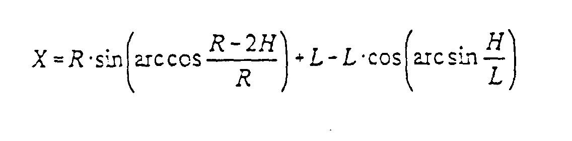
- S =
- Stellweg der Herzstückspitze (10),
- B =
- Breite der Herzstückspitze (10),
- L =
- Abstand Achse (126) der Wippe (118) zu der Achse (123) bzw. (131) des Rollenelementes (122) bzw. (130),
- X =
- Abstand zwischen Längsrand (132) bzw. (134) und einer eine gedachte Verlängerung der Unterseite (120) der Herzstückspitze (10) schneidende, von der Achse (123) bzw. (131) ausgehenden Normalen,
- R =
- Radius des Rollenelementes (122) bzw. (130)
- H =
- Hubhöhe der Herzstückspitze (10).
- S =
- Travel of the centerpiece tip (10),
- B =
- Width of the centerpiece tip (10),
- L =
- Distance axis (126) of rocker (118) to axis (123) or (131) of roller element (122) or (130),
- X =
- Distance between the longitudinal edge (132) or (134) and a normal extending from the axis (123) or (131) and intersecting an imaginary extension of the underside (120) of the frog tip (10),
- R =
- Radius of the roller element (122) or (130)
- H =
- Lifting height of the centerpiece tip (10).
Auch sei bemerkt, daß die das Anheben bzw. Absenken bewirkenden Lösungsmöglichkeiten, soweit die Verschlußklammern nicht betroffen sind, auch außerhalb der Verschlußfelder liegen können.It should also be noted that the solution options that cause the lifting or lowering, as far as the locking clips are not affected, also outside the Locking fields can lie.
Claims (17)
- A frog tip (10) that with its underside (120) is movably arranged between wing rails (12, 14) on a base such as a slide chair and is when in a position contacting the wing rails or in the end position lockable preferably by means of at least one locking clamp (28, 30, 88, 90) accommodated in guided manner in a locking piece (32, 34),
wherein
the frog tip (10) in its positions contacting the wing rails (12, 14) is supported on the base and arranged at a distance from the base between the positions contacting the wing rails (12, 14). - Frog tip according to Claim 1,
wherein
an element (94) extends indirectly or directly from the foot side of the frog tip (10) and has a projection (92) extending along or approximately along the central axis (106) of the frog tip (10), and wherein the element interacts with a roller element (96) whose rotation axis (114) runs inside or approximately inside a symmetry plane (116) running between the wing rails (12, 14). - Frog tip according to Claim 1 or Claim 2,
wherein
the element (94) preferably designed as a rectangular block has on the roller element side a surface (108) made up of two outer concave sections (110, 112) and a preferably plateau-like central section forming the projection (92). - Frog tip according to Claim 3,
wherein
the curvature radii of the outer sections (110, 112) correspond to or approximately to the curvature radius of the roller element (96) at least in that area adjoining the central section (92). - Frog tip according to at least one of the preceding claims,
wherein
a roller element having an axis on or approximately on the central axis (106) of the frog tip (10) extends from the underside of the frog tip and in turn interacts with an element having a projection extending in the direction of the frog tip, said projection running in or approximately in a symmetry plane running between the wing rails. - Frog tip according to Claim 1,
wherein
at least one rocker (118) supporting the frog tip (10) is arranged underneath the frog tip and whose rotation axis (126) is in or approximately in a symmetry plane (116) running between the wing rails (12, 14). - Frog tip according to at least one of the preceding claims,
wherein
with two or more rockers allocated to the frog tip (10) and having the same dimensions their rotation axes are equidistantly spaced to one another and to the inside longitudinal edges of the frog tip when viewed in a plane vertical to the rotation axes. - Frog tip according to at least Claim 7,
wherein
the rocker (118) comprises a beam (124) with rollers (122, 130) arranged symmetrically to the rotation axis (126) and interacting with the frog tip underside (120). - Frog tip according to at least one of the preceding claims,
wherein
the frog tip (10) in the position contacting one of the wing rails (12, 14) rests on the roller (122) close to the wing rail (12) and touches the other roller (130) with its longitudinal edge (132) facing away from the wing rail. - Frog tip according to at least Claim 9,
wherein
between the distance (L) between the rotation axis (126) of the beam (124) and the axes (123, 131) of the respective rollers (122, 130), the frog tip width (B), the setting path (S) of the frog tip (10) and the radius (R) of the rollers (122, 133), the following relationships apply:where
- X =
- the distance between the longitudinal edges (132, 134) of the frog tip underside (120) and a normal extending from the axes (123, 131) of the rollers (122, 130) and intersecting an imaginary extension of the underside (120) of the frog tip (10),
- H =
- lift height of frog tip (10).
- Frog tip according to at least Claim 1,
wherein
the locking clamp (28, 30) extends movably preferably in the longitudinal direction of the frog tip (10) from a locking clamp receptacle (20, 22) connected to the frog tip, wherein at least one roller element (48, 54) extends from the locking clamp and is grippable by a sliding element (40) passing through the locking piece (32, 34) and movable vertically or approximately vertically to the frog tip longitudinal axis, and wherein the roller element is supportable on a support (42) running parallel or approximately parallel to the movement direction of the sliding element and in turn arranged stationary relative to the locking piece or extending therefrom. - Frog tip according to at least one of the preceding claims,
wherein
when the frog tip is locked the roller element (48) is held in a receptacle (80, 84) limited at least in some areas by the sliding element (40) and the support (42). - Frog tip according to at least one of the preceding claims,
wherein
during movement of the frog tip (10) from one contacting position into the other contacting position the roller element (48) is grippable by a ramp-shaped section (72) of the sliding element (40) for lifting the frog tip away from the base. - Frog tip according to at least one of the preceding claims,
wherein
the roller element (48, 54) extends from an arm (44, 46) of the locking clamp (28, 30, 98) running underneath a locking rail (36, 38) associated with one of the wing rails (12, 14). - Frog tip according to at least one of the preceding claims,
wherein
two roller elements (48, 52; 52, 54) extend from the arms (44, 46) of the locking clamp (28, 30) and wherein one roller element each is arranged in the end parts of the arms. - Frog tip according to at least one of the preceding claims,
wherein
when the frog tip (10) is locked each of the roller elements (48, 50; 52, 54) is fixed in mountings formed by sections of the sliding element (40) and the support (42). - Frog tip according to at least one of the preceding claims,
wherein
at least one roller element interacting with the underside of the frog tip (10) is allocated to said frog tip (10).
Applications Claiming Priority (3)
| Application Number | Priority Date | Filing Date | Title |
|---|---|---|---|
| DE4315559A DE4315559A1 (en) | 1993-05-10 | 1993-05-10 | Centerpiece tip |
| DE4315559 | 1993-05-10 | ||
| PCT/EP1994/001438 WO1994026976A1 (en) | 1993-05-10 | 1994-05-06 | Crossing nose |
Publications (2)
| Publication Number | Publication Date |
|---|---|
| EP0698144A1 EP0698144A1 (en) | 1996-02-28 |
| EP0698144B1 true EP0698144B1 (en) | 1998-08-19 |
Family
ID=6487716
Family Applications (1)
| Application Number | Title | Priority Date | Filing Date |
|---|---|---|---|
| EP94917581A Expired - Lifetime EP0698144B1 (en) | 1993-05-10 | 1994-05-06 | Crossing nose |
Country Status (10)
| Country | Link |
|---|---|
| EP (1) | EP0698144B1 (en) |
| KR (1) | KR960702562A (en) |
| AT (1) | ATE169976T1 (en) |
| AU (1) | AU6925394A (en) |
| DE (2) | DE4315559A1 (en) |
| DK (1) | DK0698144T3 (en) |
| ES (1) | ES2121209T3 (en) |
| NO (1) | NO954505L (en) |
| TW (1) | TW258765B (en) |
| WO (1) | WO1994026976A1 (en) |
Families Citing this family (7)
| Publication number | Priority date | Publication date | Assignee | Title |
|---|---|---|---|---|
| DE19607588A1 (en) * | 1996-02-29 | 1997-09-04 | Butzbacher Weichenbau Gmbh | Arrangement for holding down a centerpiece tip |
| DE10215280B4 (en) * | 2002-02-07 | 2006-01-12 | Schreck-Mieves Gmbh | Heart lifting device |
| AT412350B (en) | 2002-04-23 | 2005-01-25 | Vae Eisenbahnsysteme Gmbh | ROLLING DEVICE FOR A MOVING HEARTPIECE POINT |
| DE202009001906U1 (en) | 2009-02-25 | 2010-07-22 | Voestalpine Bwg Gmbh & Co. Kg | Centerpiece in the form of a forged block tip |
| AT508027B1 (en) * | 2009-03-30 | 2010-10-15 | Enzesfeld Caro Metallwerke Ag | SOFT FOR RAILWAY INSTALLATIONS |
| ES2365142B1 (en) * | 2011-06-01 | 2012-08-14 | Felguera Melt, S.A. | SYSTEM FOR THE DECREASE OF OPERATING EFFORTS IN THE PUNTA MOBILE RAILWAY CROSSINGS. |
| DE102012017982A1 (en) | 2012-09-12 | 2014-03-13 | Schwihag Ag | Heart rolling device |
Family Cites Families (6)
| Publication number | Priority date | Publication date | Assignee | Title |
|---|---|---|---|---|
| US2533929A (en) * | 1945-09-18 | 1950-12-12 | Griffin W Gray | Rail switch point lifting means |
| DE1272951B (en) * | 1966-12-21 | 1968-07-18 | Kloeckner Werke Ag | Simple heart with swiveling heart tip |
| CH456667A (en) * | 1967-05-30 | 1968-07-31 | Tech Pour L Ind Nouvelle Sa St | Cuttable point lock for railway switches |
| AT346885B (en) * | 1977-02-10 | 1978-11-27 | Voest Ag | SWITCH |
| DE4041264A1 (en) * | 1990-12-21 | 1992-06-25 | Peddinghaus Carl Dan Gmbh | DEVICE FOR Raising the Tongue Rail of a Switch |
| WO1994002682A1 (en) * | 1992-07-22 | 1994-02-03 | Bwg Butzbacher Weichenbau Gmbh | Roller device |
-
1993
- 1993-05-10 DE DE4315559A patent/DE4315559A1/en not_active Withdrawn
-
1994
- 1994-05-06 EP EP94917581A patent/EP0698144B1/en not_active Expired - Lifetime
- 1994-05-06 AU AU69253/94A patent/AU6925394A/en not_active Abandoned
- 1994-05-06 ES ES94917581T patent/ES2121209T3/en not_active Expired - Lifetime
- 1994-05-06 KR KR1019950704920A patent/KR960702562A/en not_active Withdrawn
- 1994-05-06 DK DK94917581T patent/DK0698144T3/en active
- 1994-05-06 AT AT94917581T patent/ATE169976T1/en active
- 1994-05-06 DE DE59406741T patent/DE59406741D1/en not_active Expired - Lifetime
- 1994-05-06 WO PCT/EP1994/001438 patent/WO1994026976A1/en not_active Ceased
- 1994-07-06 TW TW083106164A patent/TW258765B/zh not_active IP Right Cessation
-
1995
- 1995-11-09 NO NO954505A patent/NO954505L/en unknown
Also Published As
| Publication number | Publication date |
|---|---|
| KR960702562A (en) | 1996-04-27 |
| NO954505D0 (en) | 1995-11-09 |
| EP0698144A1 (en) | 1996-02-28 |
| DE59406741D1 (en) | 1998-09-24 |
| NO954505L (en) | 1995-11-09 |
| ATE169976T1 (en) | 1998-09-15 |
| AU6925394A (en) | 1994-12-12 |
| TW258765B (en) | 1995-10-01 |
| ES2121209T3 (en) | 1998-11-16 |
| DK0698144T3 (en) | 1999-05-25 |
| WO1994026976A1 (en) | 1994-11-24 |
| DE4315559A1 (en) | 1994-11-17 |
Similar Documents
| Publication | Publication Date | Title |
|---|---|---|
| DE2743835C2 (en) | Device for moving an upper part parallel to a fixed lower part by means of a cross guide | |
| EP0455153B1 (en) | Locking device for a switch point with stock rails | |
| EP0406647B1 (en) | Flush-mounted guiding system | |
| WO1993023624A1 (en) | Expansion joint for part of a railway track | |
| EP0698144B1 (en) | Crossing nose | |
| EP0593409B1 (en) | Device to ease the change movement for moveable rails or trackparts | |
| DE102014212074A1 (en) | Device for supporting a tongue rail of a switch | |
| CH669231A5 (en) | SLIDING CHAIR FOR SWITCHES AND CROSSINGS. | |
| WO1994005858A1 (en) | Rail fastening device | |
| EP0305592B1 (en) | Clamping device for rails | |
| DE3904026A1 (en) | SLIDING INSERT FOR CLOSED TONGUE DEVICES AND SLIDING SURFACES FOR MOVABLE HEART TIP TIPS, AND METHOD FOR FASTENING SUCH A SLIDING INSERT TO THE SLIDING BED OF ROLLER RAIL LOCKING DEVICES | |
| AT410809B9 (en) | SOFT TO RAIL OF RAILWAY TRAFFIC | |
| DE2607435C3 (en) | Drawer guide with protection against tilting to the side | |
| DE2438756C2 (en) | Track switch, especially high-speed switch | |
| EP0703317B1 (en) | Rolling apparatus | |
| EP0771378A1 (en) | Setting arrangement | |
| DE102018217958A1 (en) | Transport system for transporting containers along a transport track and trolley | |
| DE20204325U1 (en) | seating | |
| DE2736145A1 (en) | Guidance system for marking stylus - has pairs of rollers arranged at corners of triangle to run on slides | |
| DE9211526U1 (en) | Device for fastening a rail | |
| EP0652996B1 (en) | Roller device | |
| DE4224158A1 (en) | Roller mechanism for switch rail on railway points - consists of fixed roller and guide plate fixed to underside of switch rail acting as carriage for slide chair | |
| DE2603001B2 (en) | Guide rail and trolley with the center of gravity above the guide rail | |
| DE3903745C2 (en) | ||
| DE202010018006U1 (en) | Switch for railway systems |
Legal Events
| Date | Code | Title | Description |
|---|---|---|---|
| PUAI | Public reference made under article 153(3) epc to a published international application that has entered the european phase |
Free format text: ORIGINAL CODE: 0009012 |
|
| 17P | Request for examination filed |
Effective date: 19951111 |
|
| AK | Designated contracting states |
Kind code of ref document: A1 Designated state(s): AT DE DK ES FR NL SE |
|
| 17Q | First examination report despatched |
Effective date: 19961015 |
|
| GRAG | Despatch of communication of intention to grant |
Free format text: ORIGINAL CODE: EPIDOS AGRA |
|
| GRAG | Despatch of communication of intention to grant |
Free format text: ORIGINAL CODE: EPIDOS AGRA |
|
| GRAG | Despatch of communication of intention to grant |
Free format text: ORIGINAL CODE: EPIDOS AGRA |
|
| GRAH | Despatch of communication of intention to grant a patent |
Free format text: ORIGINAL CODE: EPIDOS IGRA |
|
| GRAH | Despatch of communication of intention to grant a patent |
Free format text: ORIGINAL CODE: EPIDOS IGRA |
|
| GRAA | (expected) grant |
Free format text: ORIGINAL CODE: 0009210 |
|
| AK | Designated contracting states |
Kind code of ref document: B1 Designated state(s): AT DE DK ES FR NL SE |
|
| REF | Corresponds to: |
Ref document number: 169976 Country of ref document: AT Date of ref document: 19980915 Kind code of ref document: T |
|
| REF | Corresponds to: |
Ref document number: 59406741 Country of ref document: DE Date of ref document: 19980924 |
|
| ET | Fr: translation filed | ||
| REG | Reference to a national code |
Ref country code: ES Ref legal event code: FG2A Ref document number: 2121209 Country of ref document: ES Kind code of ref document: T3 |
|
| RAP2 | Party data changed (patent owner data changed or rights of a patent transferred) |
Owner name: BWG BUTZBACHER WEICHENBAU GESELLSCHAFT MBH & CO. K |
|
| NLT2 | Nl: modifications (of names), taken from the european patent patent bulletin |
Owner name: BWG BUTZBACHER WEICHENBAU GESELLSCHAFT MBH & CO. K |
|
| REG | Reference to a national code |
Ref country code: DK Ref legal event code: T3 |
|
| PLBE | No opposition filed within time limit |
Free format text: ORIGINAL CODE: 0009261 |
|
| STAA | Information on the status of an ep patent application or granted ep patent |
Free format text: STATUS: NO OPPOSITION FILED WITHIN TIME LIMIT |
|
| 26N | No opposition filed | ||
| PGFP | Annual fee paid to national office [announced via postgrant information from national office to epo] |
Ref country code: SE Payment date: 20010521 Year of fee payment: 8 Ref country code: DK Payment date: 20010521 Year of fee payment: 8 |
|
| PG25 | Lapsed in a contracting state [announced via postgrant information from national office to epo] |
Ref country code: SE Free format text: LAPSE BECAUSE OF NON-PAYMENT OF DUE FEES Effective date: 20020507 |
|
| PG25 | Lapsed in a contracting state [announced via postgrant information from national office to epo] |
Ref country code: DK Free format text: LAPSE BECAUSE OF NON-PAYMENT OF DUE FEES Effective date: 20020531 |
|
| REG | Reference to a national code |
Ref country code: DK Ref legal event code: EBP |
|
| EUG | Se: european patent has lapsed | ||
| PGFP | Annual fee paid to national office [announced via postgrant information from national office to epo] |
Ref country code: ES Payment date: 20120525 Year of fee payment: 19 |
|
| PGFP | Annual fee paid to national office [announced via postgrant information from national office to epo] |
Ref country code: AT Payment date: 20120511 Year of fee payment: 19 |
|
| PGFP | Annual fee paid to national office [announced via postgrant information from national office to epo] |
Ref country code: DE Payment date: 20130522 Year of fee payment: 20 |
|
| PGFP | Annual fee paid to national office [announced via postgrant information from national office to epo] |
Ref country code: FR Payment date: 20130603 Year of fee payment: 20 Ref country code: NL Payment date: 20130521 Year of fee payment: 20 |
|
| REG | Reference to a national code |
Ref country code: DE Ref legal event code: R071 Ref document number: 59406741 Country of ref document: DE |
|
| REG | Reference to a national code |
Ref country code: NL Ref legal event code: V4 Effective date: 20140506 |
|
| REG | Reference to a national code |
Ref country code: AT Ref legal event code: MK07 Ref document number: 169976 Country of ref document: AT Kind code of ref document: T Effective date: 20140506 |
|
| REG | Reference to a national code |
Ref country code: ES Ref legal event code: FD2A Effective date: 20140711 |
|
| PG25 | Lapsed in a contracting state [announced via postgrant information from national office to epo] |
Ref country code: DE Free format text: LAPSE BECAUSE OF EXPIRATION OF PROTECTION Effective date: 20140507 |
|
| PG25 | Lapsed in a contracting state [announced via postgrant information from national office to epo] |
Ref country code: ES Free format text: LAPSE BECAUSE OF EXPIRATION OF PROTECTION Effective date: 20140507 |