EP0697833B1 - Endoskop mit seitlichen kabelabgängen - Google Patents
Endoskop mit seitlichen kabelabgängen Download PDFInfo
- Publication number
- EP0697833B1 EP0697833B1 EP95913079A EP95913079A EP0697833B1 EP 0697833 B1 EP0697833 B1 EP 0697833B1 EP 95913079 A EP95913079 A EP 95913079A EP 95913079 A EP95913079 A EP 95913079A EP 0697833 B1 EP0697833 B1 EP 0697833B1
- Authority
- EP
- European Patent Office
- Prior art keywords
- housing
- endoscope
- working instrument
- shaft
- axis
- Prior art date
- Legal status (The legal status is an assumption and is not a legal conclusion. Google has not performed a legal analysis and makes no representation as to the accuracy of the status listed.)
- Expired - Lifetime
Links
- 230000003287 optical effect Effects 0.000 claims description 46
- 210000003813 thumb Anatomy 0.000 claims description 15
- 230000005540 biological transmission Effects 0.000 claims description 12
- 238000010276 construction Methods 0.000 description 18
- 230000033001 locomotion Effects 0.000 description 18
- 210000003811 finger Anatomy 0.000 description 9
- 238000013519 translation Methods 0.000 description 8
- 230000014616 translation Effects 0.000 description 8
- 230000008878 coupling Effects 0.000 description 7
- 238000010168 coupling process Methods 0.000 description 7
- 238000005859 coupling reaction Methods 0.000 description 7
- 238000013461 design Methods 0.000 description 4
- 239000000835 fiber Substances 0.000 description 4
- 239000004020 conductor Substances 0.000 description 3
- 238000011010 flushing procedure Methods 0.000 description 2
- 238000012360 testing method Methods 0.000 description 2
- 238000012549 training Methods 0.000 description 2
- XLYOFNOQVPJJNP-UHFFFAOYSA-N water Substances O XLYOFNOQVPJJNP-UHFFFAOYSA-N 0.000 description 2
- 206010038743 Restlessness Diseases 0.000 description 1
- 238000004140 cleaning Methods 0.000 description 1
- 238000005516 engineering process Methods 0.000 description 1
- 230000002349 favourable effect Effects 0.000 description 1
- 210000000245 forearm Anatomy 0.000 description 1
- 238000009434 installation Methods 0.000 description 1
- 238000009413 insulation Methods 0.000 description 1
- 238000002372 labelling Methods 0.000 description 1
- 239000007788 liquid Substances 0.000 description 1
- 230000007774 longterm Effects 0.000 description 1
- 238000003801 milling Methods 0.000 description 1
- 239000013307 optical fiber Substances 0.000 description 1
- 230000002093 peripheral effect Effects 0.000 description 1
- 210000002307 prostate Anatomy 0.000 description 1
- 210000001519 tissue Anatomy 0.000 description 1
- 238000012546 transfer Methods 0.000 description 1
- 210000003708 urethra Anatomy 0.000 description 1
Images

Classifications
-
- A—HUMAN NECESSITIES
- A61—MEDICAL OR VETERINARY SCIENCE; HYGIENE
- A61B—DIAGNOSIS; SURGERY; IDENTIFICATION
- A61B1/00—Instruments for performing medical examinations of the interior of cavities or tubes of the body by visual or photographical inspection, e.g. endoscopes; Illuminating arrangements therefor
- A61B1/012—Instruments for performing medical examinations of the interior of cavities or tubes of the body by visual or photographical inspection, e.g. endoscopes; Illuminating arrangements therefor characterised by internal passages or accessories therefor
- A61B1/018—Instruments for performing medical examinations of the interior of cavities or tubes of the body by visual or photographical inspection, e.g. endoscopes; Illuminating arrangements therefor characterised by internal passages or accessories therefor for receiving instruments
Definitions
- the invention relates to an endoscope in the preamble of the claim 1 Art.
- a urological resector is presented, which in the hereinafter referred to as the resector.
- lateral cable outlets are provided.
- these are a fiber optic cable and a RF cables.
- the resector has a working tool with the one under optical Observation through optics in an operating field the distal end of the shaft part can be worked.
- a cutting sling by the Handle device is actuated to axial movement and the an RF line is connected, which is also a has lateral cable outlet.
- the rotation of the working instrument is controlled always via the handle device, by the hand of the surgeon held and rotated while driving the working instrument becomes.
- the lateral cable outlets form during such rotary movements a big obstacle. Since they are state of the art are rotatably connected to the handle device, each Rotation movement swung the cables. With multiple turns The cables wrap around the end body over larger angles. In addition, the high weight of the outgoing cables disturbs in particular the very heavy fiber optic cable, which is in different angular position different and therefore strong disruptive torques result.
- the camera is at the proximal end of the endoscope to that provided according to the prior art Eyepiece attached, with the cable of the camera approximately in the direction the shaft axis extends from the camera.
- This cable does not exert disruptive torques, but hinders it Operator operating the endoscope, since it is the Turning the grip device wraps around his forearm.
- Another disadvantage of the known resector is the location of the Thumb ring trained proximal handle part, the side next the end body is arranged. With rotations must therefore always can be gripped with the thumb around the end body, whereby the free handling is restricted.
- Pistol grip instruments with cable outlets arranged in the grip for the camera cable and the fiber optic cable. Pistol grip instruments but have the disadvantage that you only turn are difficult because the hand is fixed on the pistol grip only slight rotations of the instrument are possible. A rotary control of the working instrument via the handle device is therefore not possible with such instruments. To do this separate turning devices required, as can be seen from the extensive literature on pistol grip instruments.
- the object of the present invention is an endoscope of the type mentioned at the beginning to create an easy rotary control made possible by the surgeon without cable interference.
- the cable outlets are the same as for the State-of-the-art devices, to the side of the end body outgoing, but on a housing opposite the working instrument and thus also towards the Handle device is freely rotatable.
- the cables can be under hang their own weight down, the cable outlets point down. It is a free rotation control of the Working instrument possible by the handle device without twist the cables. Since the cable outlets distal from proximal handle part, this is through the thumb of the Operators can be operated completely freely on all sides, which makes the free Rotary control is promoted.
- Working with one Endoscope with rotary movements especially in the Case of a urological resectoscope, in which such Rotational movements are very common, so it is much easier.
- the features of claim 3 are provided.
- the entire handle device is proximal from the rotatable housing is provided, so that it as a whole, ie with all fingers of the operating hand of the surgeon completely free of Cables can be operated equally well from all sides.
- the optics can be used in an advantageous construction Holder of the working instrument or used as part of this become.
- the optics can just as well rotate with it be connected to the housing. This can, for example, from Be an advantage if, for certain reasons, rotating the optics and the lens when the working instrument is rotated should be prevented.
- a camera is provided to simplify the cable connection and connected to the housing to hold the image in place is and that which lies in the bearing axis of the housing observed proximal end of the optics, the camera must immediately be arranged in the bearing axis or at least with one Interact with the beam deflector.
- an endoscope According to claim 2, there are no problems, but they do in an endoscope according to claim 3, in which the rotary control must take place from the distal handle part over the place which the camera or the beam deflection device in the axis of rotation intervenes.
- the gear transmission also has the advantage that the rotary coupling of the working instrument to the handle device can be selected with different translations, either 1: 1, as with a rigid connection, or with Fast or slow translation. It can do the translation of the gear transmission can thus be selected, for example, that even with a slight twist of the handle means a twist of the working instrument is reached over a full 360 °. On the other hand, it can also be used to turn the Working instrument the translation be chosen so that for a certain rotation of the working tool a larger one Angular movement of the handle device is required.
- the translation can be adjustable with a manual transmission.
- Working tools usually need to be operated in some way become. This is usually done by one in the shaft device installed operating rod with which, for example, in In the case of a urological resector, the cutting loop subjected to HF for cutting movement - depending on the design of the handle device - is pushed forward or back. In the case of pliers their jaws are opened and closed via the operating rod. The actuation takes place in the usual way fully the handle device forth. The features of the claim are therefore advantageous 10 provided.
- the push rod of the actuator is in the housing. This means that it is always in an angular position, in which they do not interfere with the camera or the cables can. At its ends it stands in a longitudinally rotating engagement with coaxial ones Surfaces on the working instrument and on the handle and a longitudinal adjustment movement between them for actuation of the working instrument transferred.
- the finger grip on the finger opposite the thumb or the endoscope attacking hand, can, as in the aforementioned stand the technology can be designed as a handle bar, but can also as rotationally symmetrical disc or in particular designed as a ring be at the fingertips only.
- the cables connected inwards from the cable outlets mostly run to facilities using the working tool rotate. These are, for example, electrical connections to the working instrument or to the fiber optic cable, which is usually runs within the optics, mostly with the working instrument is rotatably connected.
- the features are advantageous for this of claim 12 provided.
- the slewing rings can be provided in different ways, for example via electrical or optical slip ring connections.
- a light guide is when the optics are rotatable with the working instrument is connected, advantageously via a rotary connection with the Features of claim 13 connected.
- Such slewing rings have proven themselves in the state of the art and stand out characterized by great simplicity.
- An HF line e.g. in the case of urological resectoscopes with HF exposure Cutting loop is required is advantageous with a slewing ring connected according to the features of claim 14.
- This slewing ring avoids the slewing ring otherwise of slip lines provided by HF lines and is characterized by high long-term strength and insulation security out.
- the camera itself sits this in the side wall of the housing and can be very easy there be removable, for example for cleaning purposes of the endoscope.
- a urological resectoscope is known from DE 41 01 472 A1, in which an outer shaft rotates freely on the shaft device is stored.
- This construction has the advantage that the outer shaft in the event of twisting of the working instrument without affecting friction the patient's rotation test remains.
- Using such an endoscope are advantageous the features of Claim 16 provided. In this way, the case with the cable outlets and, if necessary, with the camera through the outer shaft lying in the patient's rotation test is held.
- This construction gives the possibility of all of the endoscope outgoing connections, both the electrical and optical cable as well as the supply and discharge of the rinsing liquid required hoses for the required rotary movements storage of the working tool.
- An essential one Another advantage of such a construction is that the Rotary control of the working instrument much easier occurs because the friction of the shaft in the patient is switched off.
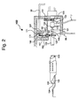
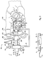
- Figures 1 and 2 show in a highly schematic Axial sectional view of embodiment variants of a first embodiment of the endoscope according to the invention, while Fig. 3 in 1 is a structurally very simplified second Embodiment shows.
- the endoscope shown in Figure 1 consists essentially of a shaft part 1 and an end body 2 on the proximal End of the shaft part 1 is arranged.
- an optic is provided in an optic tube 3, which has a lens 4 at its distal end and at its proximal end End 5 is open. It is there from a side standing Viewed video camera 6 with connection cable 7 via a deflection prism 8, which is connected to the camera 6 via a support 9 is.
- the camera 6 can be plugged into a connector 10 in the side wall a housing 11 arranged.
- the housing 11 is rotatable in one Groove 12 of a bearing piece 13 which is distal from the proximal End 5 is attached to the optical tube 3.
- the bearing axis, about which the housing 11 rotates coincides with the optical axis of the Optics tube 3 provided optics together.
- the camera 6 can So with the housing 11 while maintaining the optical Insight can be rotated around the optical tube 3.
- a grip device 14 which has a proximal one Has grip part and a distal grip part.
- the proximal part of the handle is designed as a thumb ring 15, while the distal handle part consists of a handle bar 16.
- the thumb ring 15 is at 17 rotatably connected to the proximal ends of two slide rods 18, running parallel to the bearing axis on a rotating piece 19 are attached with which the entire handle device 14 coaxially Bearing axis rotatably mounted in a bore 20 of the housing 11 is.
- the handle bar 16 is a moving part of the handle device 14 longitudinally displaceable on the slide rods 18 and with a Spring 21 supported against its proximal end.
- the handle device 14 serves to control the rotation of the shaft part 1 provided, in the embodiment with the optic tube 3 rotatably associated working instrument. So you must with the working tool be rotatably coupled, what in the embodiment takes place via the optical tube 3. As Figure 1 shows, however, ends the optical tube 3 at its proximal end 5 at a distance from the handle device 14. The camera 6 with the deflection prism reaches into this gap 8th.
- the proximal end area of the Optic tube 3 and on the inside of the housing 11 End of the rotating piece 19 of the handle device 14 is the same large gear 22, 23 attached coaxially to the bearing axis.
- the two Gears 22, 23 mesh with a toothed roller 24, with their Axis 25 on the housing 11 parallel and outside the bearing axis is rotatably mounted.
- the housing 11 can be any are rotated around the optical tube 3 and the handle device 14, a torsionally rigid between the latter via the toothed roller 24 Coupling is maintained without the rotary coupling device with the intervention of the camera in the area of the main axis collides with the deflection prism 8.
- the optical tube 3 has a flexible light guide in its interior 26, which emits in the region of the lens 4 in its viewing direction ends.
- the light guide 26 is at 27 from the optics tube 3 led out, so at a point within the housing 11. Er runs from there several times around the optical tube 3 and then to a passage 28 in the side wall of the housing 11, the advantageous as a plug connection for a further optical fiber cable is trained.
- This type of rotary connection of the light guide 26 between the Optical tube 3 and the housing 11 allows a large one Angle of rotation of e.g. 720 °, but still requires a rotation angle limitation of the housing 11 relative to the optical tube 3.
- a gear wheel 29 is provided which engages with the worm a worm 30, which is parallel to the axis 25 of the toothed roller 24 is arranged rotatably in the housing 11.
- end stops 31 are formed against which Gear 29 in its screwing motion on the worm 30 in the Movement-limiting terminal is coming.
- the gear 29 meshes with the toothed roller 24 and when it rotates on the Screw 30 screwed. It reaches one of the end stops 31, the further rotation of the housing 11 is opposite blocked the optic tube 3.
- the shaft part 1 has a the inner tube 32 surrounding the optical tube 3, which with a proximal end piece 33 on the optical tube 3 and thus on the end body 2 is attached.
- the end piece 33 is longitudinally displaceable interspersed and attached to a sliding piece 35, which on the optical tube 3 is mounted to be longitudinally displaceable.
- the slider 35 is used to operate any distal End area of the inner shaft 32 of intended working instruments, such as pliers or the like.
- the actuation takes place from the moving part of the handle device 14, ie in Embodiment of the handle bar 16 ago.
- An advantageous embodiment is a push rod 36 provided that the end walls of the housing 11 in holes 37 slidably interspersed, i.e. longitudinally displaceable parallel to the main axis is stored in the housing 11. Angled transverse to the main axis End pieces 38 and 39 of the push rod 36 grip with forks 38 ' and 39 'in circumferential grooves 40 and 41 on the sliding piece 35th or the handle bar 16.
- a cutting loop 44 exposed to high frequency distal end of the actuating rod 34 is provided.
- Tissue cuts can be made.
- An endoscope equipped in this way is referred to as a resector in urology.
- the actuation line In this case, 34 is to be designed as an insulated conductor.
- a conductive connection must be made in the end body 2 of the endoscope a connection 45 to the housing 11 are created, which as Plug is designed for a further RF cable.
- the Spring spiral 48 engages with its inner end 47 in a bore 56 of the bearing piece arranged fixed on the optical tube 3 13 and is fixed there against rotational movements.
- the spring spiral 48 can be in the manner of an unrest, as is the case with mechanical pocket watches is used, larger angle of rotation between its inner Compensate end 47 and its outer end 49, so the rotational movements of the housing 11 in relation to the optical tube 3.
- the shaft part 1 has a all inner parts 3, 32, 34 surrounding outer shaft 50, which is attached proximally to a ring 51 which is on the end piece 33 of the inner shaft 32 is mounted.
- Flush water connections 52 and 53 are provided with which constantly Flushing water through the interior of the inner shaft 32 the operating area fed and through distal openings 54 in the outer shaft 50 is suctioned off.
- the outer shaft 50 can be coaxial with the bearing axis of the housing 11 can be rotatably supported and with this for Example of the connecting strut 55 shown on his Ring 51 is fixed, be coupled in a rotationally fixed manner.
- the housing 11 remains then when the optical tube 3 and the cutting loop are twisted 44 by means of the coupling to the rotationally fixed in the body of the
- the patient's outer shaft 50 is held in a rotationally fixed manner.
- the ones from Housing 11 preferably downward cable, that is Cable 7 of the camera 6, and the bushing 28 and the Connector 45 outgoing cables for the light pipe and the HF feed, then remain in a fixed position and disrupt operation not even when the instrument is turned.
- Figure 2 shows an endoscope that largely corresponds to Figure 1.
- Unchanged parts have the same reference numerals as in the figure 1 provided. It will only refer to the construction details below received, which are shown in a variant and with new Reference numerals are referred to, as far as possible, the reference numerals correspond to similar parts according to FIG. 1, namely increased by 100.
- the optics with their eyepiece 4 arranged rotatably in the optical tube 3.
- the optical tube 3 is non-rotatable with the working instrument 34, 35, 44 coupled. So the optics turn with the working instrument, while the camera 6 with the Housing 11 stands still.
- the optics tube 103 encloses a separately designed lens 160 Objective 104.
- the optics 160 are rotatably mounted in the optics tube 103 and at its distal end 105 on a bracket 161 rotatably held, which is connected to the housing 11.
- the optics tube 103 thus rotates with the working instrument, while the optics 160 rotates with the housing 11. It is therefore non-rotatable to the camera 106, which is also shown in a variant.
- it is in the bearing axis of the housing 11 arranged and with an arm 162 with the housing 11 connected.
- This embodiment can have optical advantages since the optics 104 stands rotatably to the camera 106. It also has constructive advantages in that with the optics 160 fixed in rotation, the one arranged in it Light guide 126 does not have to be rotated. It goes on direct Fixed installation routes for bushing 28 on the housing 11. Likewise, the cable 7 of the camera 6 is simple through the wall of the housing 11 because the camera 106 with the housing 11 rotates.
- Gear 122 which via the gear transmission with a gear 123 is to be coupled, which is rotatably connected to the handle device 14 is as described in FIG. 1.
- the gears 122 and 123 are different large.
- the gears 163 and 164 are also different large. So there is a gear ratio between the Handle device 14 and the optical tube 103 or the working instrument.
- the translation is chosen so that at a certain angular rotation of the handle device 14 Optical tube 103 only rotated by a much smaller angle becomes. So it can move the working instrument very sensitively become.
- a translation "into the fast” is also possible, so such that with a slight angular rotation of the handle device 14 a much larger angular rotation of the working instrument he follows.
- the working tool can therefore also, for example, like a drill or milling cutter can be rotated quickly.
- FIG. 1 The rotation angle limitation was in the construction of FIG. 1 with a gear 29 on a worm 30 between end stops 31 executed.
- Figure 2 also shows a variant of this.
- gear 166 which has an axis 167 between supports 168 and 169 is mounted, which is connected to the wall of the housing 11 are.
- the support 169 also serves as Bearing for one end of the connecting shaft 165.
- the gear 166 carries a pin 170 on one side. On the support 168, an end stop 171 is provided. Gear 166 can So turn uni a little less than 360 ° and then always comes along one or the other side of the end stop 171 in plant.
- the shaft part 1 corresponds identically to that of the embodiment of Fig. 1. Its parts are therefore with the same reference numerals Mistake. However, the end body 199 is designed differently.
- the end piece 33 is, as in the embodiment of FIG. 1, with connected to the optical tube 3, which in its training and length including the proximal end 5 corresponds to that of FIG. 1.
- a sliding piece 200 is longitudinally displaceable on the optical tube 3 stored, which corresponds to the sliding piece 35 of FIG. 1.
- Sliding piece 200 is the actuating rod with a clamping screw 201 34 of the cutting loop 44 attached and the electrical conductor to power the cutting loop 44 with one of Sliding piece 200 outgoing RF cable 202 electrically connected.
- a handle bar as a distal handle part 203, which, as FIG. 3 shows, from the index finger 204 and Middle finger or ring finger 205 of the hand 206 of the surgeon gripped becomes.
- an articulated bridge 207 of conventional design arranged Tension spring 208 The articulated bridge pulls in the version of the shown Endoscope as the actively cutting resector the sliding piece 200 and thus the cutting loop 44 in the distal direction, while by engaging the fingers on the handle bar 203 the Cutting loop 44 can be pulled in the proximal direction.
- a support ring 209 attached, on which a schematically indicated Pivot bearing 210 runs, which is a tubular distal end piece 211 of a housing 212 carries, which is basically in its function corresponds to the housing 11 of FIG. 1.
- the housing 212 is Mounted freely rotatable on the optical tube 3 via the rotary bearing 210.
- the housing 212 carries over at its proximal end Pivot bearing 213 the thumb ring 15, the thumb 214 of the surgeon is taken.
- the camera 6 with cable 7 can be inserted fixed in the peripheral wall of the housing 212.
- the Light guide 26 is in accordance with the embodiment of FIG. 1 the optics tube 3 near its proximal end 5 and led out through the wall of the housing 212.
- a 45 ° mirror 215 attached to the housing 212 is provided.
- FIG. 3 is the freely rotatable Housing 212, as the figure shows, from the hand 206 of the Surgeons. With fingers 204 and 205 the Handle bar 203 for rotary control of the working instrument seized.
- the rotary control must therefore with this construction not like that of FIG. 1 with considerable constructive Effort through the housing 212 and bypassing the Area in which the beam path of the camera 6 in the axis of rotation intervenes, be provided.
- Handle bar 203 can also be used instead of Handle bar 203 and / or another instead of the thumb ring 15 Handle part may be provided, for example a disc on the Attack the edge of the fingers.
- the light guide 26 can instead, as shown in Fig. 3, by the housing 212 to be routed, its cable outlet to another Have place of the instrument, for example in the area of End piece 33. Then the cable outlet of the light guide constantly rotated, however, just like the HF cable 202, it is distal of the entire handle device, i.e. distal of the handle bar 203 so that it does not interfere with the operator's hand when twisted.
- the housing 212 in the embodiment of FIG. 3 is the camera 6 and the deflecting mirror 215, it is with the pivot bearing 210 mounted so that its axis of rotation with the optical axis of the optical system in the optical tube 3 matches. Because the optics tube 3 sits somewhat eccentrically in the shaft part 1, the axis of rotation falls of the housing 212 not together with the shaft axis, but is slightly offset parallel to this.
Landscapes
- Health & Medical Sciences (AREA)
- Life Sciences & Earth Sciences (AREA)
- Surgery (AREA)
- Nuclear Medicine, Radiotherapy & Molecular Imaging (AREA)
- Biomedical Technology (AREA)
- Optics & Photonics (AREA)
- Pathology (AREA)
- Radiology & Medical Imaging (AREA)
- Biophysics (AREA)
- Engineering & Computer Science (AREA)
- Physics & Mathematics (AREA)
- Heart & Thoracic Surgery (AREA)
- Medical Informatics (AREA)
- Molecular Biology (AREA)
- Animal Behavior & Ethology (AREA)
- General Health & Medical Sciences (AREA)
- Public Health (AREA)
- Veterinary Medicine (AREA)
- Endoscopes (AREA)
Description
DE 41 05 326 C2.
DE 39 28 421 A1
Claims (16)
- Starres medizinisches Endoskop mit einem Schaftteil (1) und einem am proximalen Ende des Schaftteiles angeordneten Endkörper (2, 102, 199),
wobei der Schaftteil (1) wenigstens ein Arbeitsinstrument (44, 34) und eine mit einem distalen Objektiv (4, 104) versehene Optik (3, 160) aufweist,
wobei der Endkörper (2, 102, 199) wenigstens ein außerhalb der Schaftachse vom Endkörper abgehendes Kabel (49, 26, 7, 126) aufweist
und wobei der Endkörper (2, 102, 199) eine Griffeinrichtung aufweist, die zwei in bezug auf die Schaftachse beabstandet angeordnete Teile (15, 16, 203) aufweist,
wobei der distale Griffteil (16, 203) drehfest an das Arbeitsinstrument (44, 34) gekoppelt istund der proximale Griffteil (15) zur Betätigung durch den Daumen (214) des Operateurs ausgebildet ist,
dadurch gekennzeichnet,daß ein Gehäuse (11, 212) vorgesehen ist, das mit seiner Außenwand wenigstens in dem longitudinalen Bereich der Schaftachse, in dem das Kabel (49, 26, 7, 126) vom Endkörper abgeht, die Außenwand des Endkörpers (2, 102, 199) bildet,
wobei das Gehäuse (11, 212) gegenüber dem Arbeitsinstrument (44, 34) frei drehbar um eine Lagerachse gelagert ist, die in der Schaftachse liegt oder parallel zu dieser angeordnet ist
und wobei der proximale Griffteil (15) proximal vom Gehäuse (11, 212) angeordnet ist. - Endoskop nach Anspruch 1, dadurch gekennzeichnet, daß der distale Griffteil (203) distal vom Gehäuse (212) angeordnet ist.
- Endoskop nach Anspruch 1, dadurch gekennzeichnet, daß der distale Griffteil (16) proximal vom Gehäuse (11) angeordnet ist.
- Endoskop nach Anspruch 1, dadurch gekennzeichnet, daß an dem Gehäuse (11, 212) mehrere Kabel (26, 7) in wenigstens angenähert derselben Winkelstellung abgehen.
- Endoskop nach Anspruch 1, dadurch gekennzeichnet, daß am Gehäuse (11, 212) das Kabel (7) einer distal von dem proximalen Griffteil (15) angeordneten, das proximale Ende (5, 105) der Optik (3, 160) betrachtenden Kamera (6, 106) abgeht.
- Endoskop nach Anspruch 5, dadurch gekennzeichnet, daß die Kamera (6, 106) am Gehäuse (11, 212) befestigt ist und daß die Optikachse in der Lagerachse des Gehäuses (11, 212) liegt.
- Endoskop nach Anspruch 1, dadurch gekennzeichnet, daß die Optik (3) drehfest mit dem Arbeitsinstrument (44, 34) gekoppelt ist.
- Endoskop nach Anspruch 3, dadurch gekennzeichnet, daß das Arbeitsinstrument (44, 34) und der distale Griffteil (16) getrennt am Gehäuse (11) gelagert sind und über ein Zahnradgetriebe (22, 23, 24; 122, 163, 164, 123) mit außerhalb der Optikachse am Gehäuse (11) gelagerter Verbindungswelle (25, 165) drehverbunden sind.
- Endoskop nach Anspruch 8, dadurch gekennzeichnet, daß das Zahnradgetriebe (22, 23, 24; 122, 163, 164, 123) mit einem am Gehäuse (11) gelagerten Zahnrad (29, 166) kämmt, dessen Drehwinkel durch Endanschläge (31; 171) begrenzt ist.
- Endoskop nach Anspruch 8, dadurch gekennzeichnet, daß zur Betätigungsübertragung von der Griffeinrichtung (14) zum Arbeitsinstrument (44, 34) eine parallel zur Lagerachse im Gehäuse (11) längsverschiebbare Schiebestange (36) vorgesehen ist, deren Enden (39, 38) außerhalb des Gehäuses (11) in Dreheingriff mit zur Lagerachse koaxialen Flächen (41, 40) stehen, welche einerseits an einem axial verschiebbar gelagerten Bewegungsteil (16) der Griffeinrichtung (14) und andererseits an einem axial verschiebbaren Schiebestück (35) des Arbeitsinstrumentes (44, 34) vorgesehen sind.
- Endoskop nach Anspruch 1, wobei der proximale Griffteil als Daumenring (15) ausgebildet ist, dadurch gekennzeichnet, daß der Daumenring (15) in der Lagerachse des Gehäuses (11, 212) angeordnet ist.
- Endoskop nach Anspruch 1, dadurch gekennzeichnet, daß das innere Ende des Kabels (49, 26) an eine gegenüber dem Arbeitsinstrument (44, 34) drehfeste Einrichtung (13, 3) über eine Drehverbindung angeschlossen ist.
- Endoskop nach Anspruch 12 mit einem flexiblen Lichtleiter (26) in der Optik (3), dadurch gekennzeichnet, daß der Lichtleiter (26) innerhalb des Gehäuses (11) mehrfach um den proximalen Endbereich der Optik (3) gewickelt und von dort zu einer Durchführung (28) in der Seitenwand des Gehäuses (11) geführt ist, durch die er das Gehäuse durchsetzt, um von dort vom Gehäuse abzugehen.
- Endoskop nach Anspruch 12 mit einer zum Arbeitsinstrument (44, 34) führenden HF-Leitung (46) dadurch gekennzeichnet, daß das proximale Ende der HF-Leitung (46) innerhalb des Gehäuses (11) an das innere Ende (47) einer federelastischen, elektrisch leitenden Spirale (48) angeschlossen ist, die in einer Ebene quer zur Lagerachse stehend mit ihrem inneren Ende (47) am Arbeitsinstrument (34) und mit ihrem äußeren Ende (49) an einer Durchführung (45) in der Seitenwand des Gehäuses (11) fixiert ist, von der ein weiterführendes HF-Kabel vom Gehäuse abgehen kann.
- Endoskop nach Anspruch 6, dadurch gekennzeichnet, daß die Kamera (6) quer zur Lagerachse in der Seitenwand des Gehäuses (11, 212) angeordnet ist und mit einer Strahlumlenkeinrichtung (8, 215) in die Lagerachse greift.
- Endoskop nach Anspruch 1 mit einem den Schaftteil (1) umgebenden, diesem gegenüber drehbar angeordneten Außenschaft (50), dadurch gekennzeichnet, daß der Außenschaft (50) drehfest mit dem Gehäuse (11, 212) gekoppelt ist.
Applications Claiming Priority (3)
| Application Number | Priority Date | Filing Date | Title |
|---|---|---|---|
| DE4408393A DE4408393A1 (de) | 1994-03-12 | 1994-03-12 | Endoskop mit seitlichen Kabelabg{ngen |
| DE4408393 | 1994-03-12 | ||
| PCT/EP1995/000887 WO1995024856A1 (de) | 1994-03-12 | 1995-03-09 | Endoskop mit seitlichen kabelabgängen |
Publications (2)
| Publication Number | Publication Date |
|---|---|
| EP0697833A1 EP0697833A1 (de) | 1996-02-28 |
| EP0697833B1 true EP0697833B1 (de) | 2000-01-26 |
Family
ID=6512605
Family Applications (1)
| Application Number | Title | Priority Date | Filing Date |
|---|---|---|---|
| EP95913079A Expired - Lifetime EP0697833B1 (de) | 1994-03-12 | 1995-03-09 | Endoskop mit seitlichen kabelabgängen |
Country Status (3)
| Country | Link |
|---|---|
| EP (1) | EP0697833B1 (de) |
| DE (2) | DE4408393A1 (de) |
| WO (1) | WO1995024856A1 (de) |
Cited By (1)
| Publication number | Priority date | Publication date | Assignee | Title |
|---|---|---|---|---|
| DE102010027080A1 (de) * | 2010-07-13 | 2012-01-19 | Olympus Winter & Ibe Gmbh | Betätigungsvorrichtung eines Resektoskopes |
Families Citing this family (1)
| Publication number | Priority date | Publication date | Assignee | Title |
|---|---|---|---|---|
| EP4566510A1 (de) | 2023-12-08 | 2025-06-11 | Karl Storz SE & Co. KG | Chirurgisches instrument und chirurgisches system |
Family Cites Families (7)
| Publication number | Priority date | Publication date | Assignee | Title |
|---|---|---|---|---|
| DE1692416U (de) * | 1954-07-08 | 1955-02-03 | Richard Wolf | Resektoskop. |
| FR1231169A (fr) * | 1959-04-08 | 1960-09-27 | Appareil endoscope avec pince à biopsie manceuvrable en diverses positions | |
| DE8505354U1 (de) * | 1985-02-14 | 1987-01-22 | Sachse, Hans E., Prof. Dr.Med. | Endoskop zur Gewebeabtragung |
| DE3928421C2 (de) * | 1989-08-28 | 1995-10-05 | Storz Karl Gmbh & Co | Endoskop mit einer Videokamera |
| DE4101472C2 (de) * | 1991-01-19 | 1995-07-13 | Winter & Ibe Olympus | Endoskop zur transurethralen Resektion |
| DE4105326A1 (de) * | 1991-02-21 | 1992-09-03 | Wolf Gmbh Richard | Endoskop mit proximal ankuppelbarer kamera |
| WO1993025137A1 (en) * | 1992-06-05 | 1993-12-23 | Adair Edwin Lloyd | Operative electronic video endoscope |
-
1994
- 1994-03-12 DE DE4408393A patent/DE4408393A1/de not_active Withdrawn
-
1995
- 1995-03-09 EP EP95913079A patent/EP0697833B1/de not_active Expired - Lifetime
- 1995-03-09 WO PCT/EP1995/000887 patent/WO1995024856A1/de not_active Ceased
- 1995-03-09 DE DE59507682T patent/DE59507682D1/de not_active Expired - Fee Related
Cited By (1)
| Publication number | Priority date | Publication date | Assignee | Title |
|---|---|---|---|---|
| DE102010027080A1 (de) * | 2010-07-13 | 2012-01-19 | Olympus Winter & Ibe Gmbh | Betätigungsvorrichtung eines Resektoskopes |
Also Published As
| Publication number | Publication date |
|---|---|
| DE59507682D1 (de) | 2000-03-02 |
| WO1995024856A1 (de) | 1995-09-21 |
| DE4408393A1 (de) | 1995-09-14 |
| EP0697833A1 (de) | 1996-02-28 |
Similar Documents
| Publication | Publication Date | Title |
|---|---|---|
| EP3772343B1 (de) | Medizinisches instrument | |
| EP2103264B1 (de) | Medizinisches Instrument | |
| DE3603344C2 (de) | ||
| DE69318324T2 (de) | Artikulierte endoskopische chirurgische Einrichtung | |
| DE9217932U1 (de) | Endoinstrument | |
| DE3802307C2 (de) | ||
| DE4440035A1 (de) | Instrument zum Morcellieren | |
| EP2438844B1 (de) | Gelenkabschnitt eines Schafts für ein endoskopisches Instrument | |
| DE10255082A1 (de) | Endoskop | |
| DE8535164U1 (de) | Chirurgisches Greifinstrument | |
| EP1311200B1 (de) | Urologisches resektoskop mit kontaktiereinrichtung | |
| DE3303335C2 (de) | ||
| EP3720333A1 (de) | Endoskop mit schwenkbarem griffteil | |
| EP3100690A1 (de) | Instrument für die endoskopische chirurgie | |
| DE4324254C1 (de) | Chirurgisches Instrument für endoskopische Operationen | |
| DE10224336A1 (de) | Medizinisches Instrument | |
| DE102013114557B4 (de) | Medizinisches Instrument mit flexiblem Zahnriemen | |
| DE9300161U1 (de) | Chirurgisches Instrument | |
| EP1392184B1 (de) | Urologisches resektoskop für kinder | |
| EP3800496A1 (de) | Endoskopisches instrument | |
| DE4408393A1 (de) | Endoskop mit seitlichen Kabelabg{ngen | |
| DE102009037045A1 (de) | Rohrförmiger Schaft eines chirurgischen Instruments | |
| DE4042102A1 (de) | Medizinisches instrument mit einem endoskop | |
| WO2003070115A1 (de) | Medizinisches instrument | |
| WO2003082394A1 (de) | Biopsieinstrument |
Legal Events
| Date | Code | Title | Description |
|---|---|---|---|
| PUAI | Public reference made under article 153(3) epc to a published international application that has entered the european phase |
Free format text: ORIGINAL CODE: 0009012 |
|
| 17P | Request for examination filed |
Effective date: 19951020 |
|
| AK | Designated contracting states |
Kind code of ref document: A1 Designated state(s): DE FR GB IT |
|
| 17Q | First examination report despatched |
Effective date: 19990302 |
|
| GRAG | Despatch of communication of intention to grant |
Free format text: ORIGINAL CODE: EPIDOS AGRA |
|
| GRAG | Despatch of communication of intention to grant |
Free format text: ORIGINAL CODE: EPIDOS AGRA |
|
| GRAH | Despatch of communication of intention to grant a patent |
Free format text: ORIGINAL CODE: EPIDOS IGRA |
|
| GRAH | Despatch of communication of intention to grant a patent |
Free format text: ORIGINAL CODE: EPIDOS IGRA |
|
| GRAA | (expected) grant |
Free format text: ORIGINAL CODE: 0009210 |
|
| AK | Designated contracting states |
Kind code of ref document: B1 Designated state(s): DE FR GB IT |
|
| PG25 | Lapsed in a contracting state [announced via postgrant information from national office to epo] |
Ref country code: IT Free format text: LAPSE BECAUSE OF FAILURE TO SUBMIT A TRANSLATION OF THE DESCRIPTION OR TO PAY THE FEE WITHIN THE PRE;WARNING: LAPSES OF ITALIAN PATENTS WITH EFFECTIVE DATE BEFORE 2007 MAY HAVE OCCURRED AT ANY TIME BEFORE 2007. THE CORRECT EFFECTIVE DATE MAY BE DIFFERENT FROM THE ONE RECORDED.SCRIBED TIME-LIMIT Effective date: 20000126 |
|
| PGFP | Annual fee paid to national office [announced via postgrant information from national office to epo] |
Ref country code: DE Payment date: 20000205 Year of fee payment: 6 |
|
| REF | Corresponds to: |
Ref document number: 59507682 Country of ref document: DE Date of ref document: 20000302 |
|
| PGFP | Annual fee paid to national office [announced via postgrant information from national office to epo] |
Ref country code: GB Payment date: 20000303 Year of fee payment: 6 |
|
| ET | Fr: translation filed | ||
| PGFP | Annual fee paid to national office [announced via postgrant information from national office to epo] |
Ref country code: FR Payment date: 20000329 Year of fee payment: 6 |
|
| GBT | Gb: translation of ep patent filed (gb section 77(6)(a)/1977) |
Effective date: 20000320 |
|
| PLBE | No opposition filed within time limit |
Free format text: ORIGINAL CODE: 0009261 |
|
| STAA | Information on the status of an ep patent application or granted ep patent |
Free format text: STATUS: NO OPPOSITION FILED WITHIN TIME LIMIT |
|
| 26N | No opposition filed | ||
| PG25 | Lapsed in a contracting state [announced via postgrant information from national office to epo] |
Ref country code: GB Free format text: LAPSE BECAUSE OF NON-PAYMENT OF DUE FEES Effective date: 20010309 |
|
| GBPC | Gb: european patent ceased through non-payment of renewal fee |
Effective date: 20010309 |
|
| PG25 | Lapsed in a contracting state [announced via postgrant information from national office to epo] |
Ref country code: FR Free format text: LAPSE BECAUSE OF NON-PAYMENT OF DUE FEES Effective date: 20011130 |
|
| REG | Reference to a national code |
Ref country code: FR Ref legal event code: ST |
|
| PG25 | Lapsed in a contracting state [announced via postgrant information from national office to epo] |
Ref country code: DE Free format text: LAPSE BECAUSE OF NON-PAYMENT OF DUE FEES Effective date: 20020101 |