EP0697773B1 - Verfahren zum Sammeln von Zuhörerreaktionen und Datenübertragungsprotokoll - Google Patents
Verfahren zum Sammeln von Zuhörerreaktionen und Datenübertragungsprotokoll Download PDFInfo
- Publication number
- EP0697773B1 EP0697773B1 EP95304487A EP95304487A EP0697773B1 EP 0697773 B1 EP0697773 B1 EP 0697773B1 EP 95304487 A EP95304487 A EP 95304487A EP 95304487 A EP95304487 A EP 95304487A EP 0697773 B1 EP0697773 B1 EP 0697773B1
- Authority
- EP
- European Patent Office
- Prior art keywords
- response
- data packet
- unit
- characters
- units
- Prior art date
- Legal status (The legal status is an assumption and is not a legal conclusion. Google has not performed a legal analysis and makes no representation as to the accuracy of the status listed.)
- Expired - Lifetime
Links
Images


Classifications
-
- H—ELECTRICITY
- H04—ELECTRIC COMMUNICATION TECHNIQUE
- H04H—BROADCAST COMMUNICATION
- H04H20/00—Arrangements for broadcast or for distribution combined with broadcast
- H04H20/38—Arrangements for distribution where lower stations, e.g. receivers, interact with the broadcast
-
- G—PHYSICS
- G06—COMPUTING; CALCULATING OR COUNTING
- G06F—ELECTRIC DIGITAL DATA PROCESSING
- G06F15/00—Digital computers in general; Data processing equipment in general
- G06F15/02—Digital computers in general; Data processing equipment in general manually operated with input through keyboard and computation using a built-in program, e.g. pocket calculators
- G06F15/025—Digital computers in general; Data processing equipment in general manually operated with input through keyboard and computation using a built-in program, e.g. pocket calculators adapted to a specific application
-
- G—PHYSICS
- G06—COMPUTING; CALCULATING OR COUNTING
- G06Q—INFORMATION AND COMMUNICATION TECHNOLOGY [ICT] SPECIALLY ADAPTED FOR ADMINISTRATIVE, COMMERCIAL, FINANCIAL, MANAGERIAL OR SUPERVISORY PURPOSES; SYSTEMS OR METHODS SPECIALLY ADAPTED FOR ADMINISTRATIVE, COMMERCIAL, FINANCIAL, MANAGERIAL OR SUPERVISORY PURPOSES, NOT OTHERWISE PROVIDED FOR
- G06Q30/00—Commerce
- G06Q30/02—Marketing; Price estimation or determination; Fundraising
-
- G—PHYSICS
- G09—EDUCATION; CRYPTOGRAPHY; DISPLAY; ADVERTISING; SEALS
- G09B—EDUCATIONAL OR DEMONSTRATION APPLIANCES; APPLIANCES FOR TEACHING, OR COMMUNICATING WITH, THE BLIND, DEAF OR MUTE; MODELS; PLANETARIA; GLOBES; MAPS; DIAGRAMS
- G09B5/00—Electrically-operated educational appliances
- G09B5/08—Electrically-operated educational appliances providing for individual presentation of information to a plurality of student stations
- G09B5/14—Electrically-operated educational appliances providing for individual presentation of information to a plurality of student stations with provision for individual teacher-student communication
-
- G—PHYSICS
- G09—EDUCATION; CRYPTOGRAPHY; DISPLAY; ADVERTISING; SEALS
- G09B—EDUCATIONAL OR DEMONSTRATION APPLIANCES; APPLIANCES FOR TEACHING, OR COMMUNICATING WITH, THE BLIND, DEAF OR MUTE; MODELS; PLANETARIA; GLOBES; MAPS; DIAGRAMS
- G09B7/00—Electrically-operated teaching apparatus or devices working with questions and answers
- G09B7/06—Electrically-operated teaching apparatus or devices working with questions and answers of the multiple-choice answer-type, i.e. where a given question is provided with a series of answers and a choice has to be made from the answers
-
- H—ELECTRICITY
- H04—ELECTRIC COMMUNICATION TECHNIQUE
- H04H—BROADCAST COMMUNICATION
- H04H2201/00—Aspects of broadcast communication
- H04H2201/70—Aspects of broadcast communication characterised in that receivers can be addressed
-
- H—ELECTRICITY
- H04—ELECTRIC COMMUNICATION TECHNIQUE
- H04H—BROADCAST COMMUNICATION
- H04H60/00—Arrangements for broadcast applications with a direct linking to broadcast information or broadcast space-time; Broadcast-related systems
- H04H60/09—Arrangements for device control with a direct linkage to broadcast information or to broadcast space-time; Arrangements for control of broadcast-related services
- H04H60/14—Arrangements for conditional access to broadcast information or to broadcast-related services
- H04H60/15—Arrangements for conditional access to broadcast information or to broadcast-related services on receiving information
Definitions
- This invention relates to a method and apparatus for retrieving, at a base unit, user responses entered in individual remote response units.
- the invention is particularly adapted to obtaining the individual responses of audience members to a question put to them.
- the invention finds application as an educational aid for determining the comprehension level of the pupils in a class and as a commercial tool for conducting audience preference polls and the like.
- the invention may even find application for remote order entry at restaurants, commodity trading exchanges, and the like.
- a long-felt need that has eluded a practical solution is obtaining immediate feedback from audience members to a question put to them.
- the instructor may wish to occasionally pose a question to the class to monitor the comprehension level. If the class response indicates a high level of comprehension, then the instructor may wish to proceed to new material. If comprehension is less than desirable, a review of the subject matter may be appropriate.
- a marketing plan evaluation session may include presenting various options to a test audience and taking an immediate poll of the audience to determine preferences for various packaging designs, logos, advertisements, and the like.
- Response systems are of two basic types: hard-wired, in which the remote units are interconnected with the base unit by conductors, and wireless. While the hard-wired systems provide more options for designing the circuitry in a manner to provide rapid collection of the responses, the conductors discourage anything but a permanent installation in a particular room and usually at a high installation cost.
- the wireless systems provide flexibility in allowing the system to he used in various settings and to be moved at will. However, the fact that wireless systems must communicate over broadcast signals tends to limit the options in a system design. The result is that speed of response is compromised, making known wireless response systems unacceptably slow in accumulating the responses, especially if the system includes a large number of remote response units, such as 250. Additionally, the number of functions possible with wireless systems has been limited.
- a wireless remote response system in which a base unit transmits address words to remotely located response units. Each response unit identifies an address word assigned to that particular response unit and transmits a response entered by the user to the base unit in response to identification of its address word. The base unit determines that a valid word has been received from a response unit and sends an acknowledge message. The remote response unit assumes a first mode, or state, upon entry of a response by a user. The remote response unit continues to transmit a data message upon receipt of its unique address word until the central control unit transmits an acknowledge message to the transmitting response unit.
- the remote response unit Upon receipt of an acknowledge message, the remote response unit changes to a second, quiescent, state or mode. While such system is exceptionally reliable and fast, it is not without its drawbacks.
- two communication channels In order to rapidly and reliably transmit address words from the base unit to the response unit and response data from the response units to the base unit, two communication channels, operating on different frequencies, are employed so that the communication from the base unit to the remote response units can occur concurrently with the communication from the remote response units to the base unit.
- separate communication channels require increased bandwidth and are not available in all countries.
- the data format in my patent is rigid and does not readily accommodate more than one character response from the user. Thus, it is limited to responding to yes/no and multiple choice questions.
- DE 4321801 discloses apparatus for wireless connection of responses of multiple users. Interrogation signals are sent to response units which are intended to elicit a response from the units in which the user has entered a particular code or number. In this way, the base station can determine the number of responses by measuring the power of the response signals received after transmission of each of the interrogation signals. There is no disclosure of a base data packet being made up of a plurality of characters, at least a portion of the characters pertaining to different response units.
- the present invention provides a wireless remote response system for retrieving at a base unit responses from a plurality of users that are entered by the users in a plurality of remote response units, each user being provided with a response unit.
- the base unit transmits a base data packet over a wireless communication link to the plurality of remote response units, which decode the base packet and load into memory a portion of the decoded base packet at each response unit.
- Each response unit examines the characters loaded into memory and determines any character in the portion of the decoded base package that pertains to that particular response unit.
- Each remote response unit then processes any character that pertains to that particular response unit. This may include, but is not limited to assembling and transmitting a response data packet over a wireless communication link from that particular response unit to the base unit.
- the response data packet contains any response entered by the user.
- the portion of the decoded base packet loaded into memory of each remote response unit includes a plurality of characters each pertaining to a different response unit.
- the plurality of characters may include acknowledge characters to indicate that a valid response was previously received from the particular response unit.
- the plurality of characters may further include a correctness character indicative of whether a previously received response matches a correct answer in an answer key.
- the particular response unit may respond to the correctness character in several ways. It may merely provide an indication to the user that a correct or an incorrect answer was received.
- the portion of the decoded base data packet loaded into memory of each remote response unit may include a plurality of characters that pertain globally to all, or a group, of the response units.
- a particular response unit displays a first message contained in the global characters in response to a given value of the correctness character pertaining to that particular response unit and displays a second message contained in the global characters in response to a different value of the correctness character pertaining to that particular response unit.
- the remote response units may be advantageously divided into groups and the portion of the decoded base data packet loaded into memory of each remote response unit may include a designation of a group of response units to which the individually pertinent characters pertain.
- the decoded base data packet may further include a designation of which group of remote response units are to transmit a response data packet in response to the particular base data packet transmission.
- one group of response units may be receiving individually tailored messages in the same base data packet which prompts another group of response units to transmit their response data packets.
- the portion of the coded base data packet loaded into memory of each remote response unit may further include a plurality of characters globally pertaining to all of the response units.
- These global characters may be stored in memory at each of the response units for any desirable purpose, such as operating code for the microcomputers operating each response unit.
- operating code for the microcomputers operating each response unit.
- the operating code and other data for the remote response units may be downloaded from the base unit without requiring physical access to the remote response units to change out read-only-memory devices, or the like.
- the base data packet may include a designation of a desired response length from the response units.
- Each response unit responds to this designation by assembling its response data packet to include the designated number of characters specified to make up the designated response length.
- the response units may be capable of providing responses that are made up of more than one character, yet the total polling time is no longer than that necessary in order to retrieve all of the responses.
- the remote response unit may assemble a null data packet that is transmitted in response to a base data packet transmission even though a user has not entered a response. This allows diagnostics to be performed from the base unit of all of the response units in order to ensure that all of the response units are properly responding without the necessity of entering a response.
- the base data packets and response data packets are encoded and decoded according to a unique technique.
- the values of each bit are encoded as a time interval for at least one cycle of a periodic waveform by varying the time period either between successive rising edges or between successive falling edges of the periodic waveform.
- the time period between rising edges or between falling edges of successive waveforms of a transmitted signal may be varied to encode each value of each bit.
- Decoding is carried out by measuring the time intervals between rising edges, or between falling edges, of successive waveforms. In a preferred form, it is determined whether each measured time interval falls within one of at least two distinct non-overlapping time ranges in order to determine a value of each bit.
- the encoded packet will vary in time duration as a function of the value of the respective bits making up the packet.
- the content of each packet is examined prior to encoding to determine whether the majority of the bits would be encoded according to the greatest length. If so, the bits are inverted to be encoded according to a shorter length and an indication is passed along, with the transmitted data packet, of the inversion to ensure proper decoding at the receiving unit.
- the method may include determining whether each measured time interval falls within one of at least two distinct, non-overlapping time ranges in order to decode a value of each bit.
- a transmission is ignored if at least one of said measured time intervals does not fall within one of said time ranges.
- said characteristic is a number of characters making up a response data packet, whereby said response data packet length is controlled with said base data packet.
- the base data packet includes a designation of a characteristic of said base data packet.
- the characteristic of said base data packet may be a number of characters making up said base data packet.
- the method includes providing a unique identification to each of said response units and determining at each of said response units a response interval following said base data packet as a function of said characteristic of said data base packet and the unique identification of that response unit.
- the said remote response units are divided into a plurality of groups and wherein said base data packet includes a designation of a group of response units to respond to said base data packet.
- transmitting a response data packet includes transmitting a null response data packet when a user has not entered a response.
- a wireless remote response system 20 includes an instructor base station, or base unit, 22 and a plurality of remote response units 24 (Fig. 1).
- Base unit 22 includes a system controller 26 having a transmitting and receiving antenna 28, which provides a wireless communication link with transmitting and receiving antennae 30 on each of the remote response unit 24.
- Base unit 22 further includes a personal computer 32, which allows an instructor to issue commands to system controller 26 over a wired communication channel, such as a serial channel 34.
- Personal computer 32 may include operating software, not forming part of the present invention, for comparing responses received from remote response units 24 against an answer key, for tallying correct answers for each student, performing statistical analysis and the like.
- Base unit 22 may additionally be linked via telephone lines, or the like, with a central control area (not shown), which, in turn, is linked with multiple ones of a base unit 22. This allows the instructor to be located at a geographic distance from the classroom, or testing room, with at least a voice and data link to the room in which each base unit 22 is located.
- Each remote response unit 24 includes an input device, such as a keypad 36, in order to receive user responses, and a display device 38 in order to display responses entered on keypad 36, as well as information transmitted from base unit 22 in a manner set forth below.
- remote response units 24 and system controller 26 have essentially the same hardware architecture (Fig. 2).
- System controller 26 includes a first microprocessor or microcomputer 40, which receives serial communication over channel 34 from computer 32.
- Microcomputer 40 exchanges data signals over a bus 39 extending to an RF transceiver 42.
- a power management circuit 44 under the control of microcomputer 40, activates the transmitting circuitry of RF transceiver 42 over a line 43 only when it is time to transmit a data packet.
- a keypad 36 and an LED, or LCD, display 38 provide respective input and output capabilities for microcomputer 40.
- remote response unit 24 includes a microcomputer 40' which has an input/output connection over a bus 39' with an RF transceiver 42' which transmits and receives signals over antenna 30.
- a power management circuit 44' activates the transmitting circuitry of RF transceiver 42' over a line 43' only when a transmission is to occur.
- a keypad 36' and display 38' provide input/output functions for microcomputer 40'.
- Each remote response unit 24 includes a microphone 46 connected with an audio transmitter 47a, which, in turn, is connected through an audio communication link defined by the antennae, 48a, 48b to an audio receiver 47b in system controller 26.
- microcomputer 40, 40' is an 8-bit microprocessor marketed by Microchip Technology under Model No. PIC 17C42 and having 2 K byte internal ROM for control program storage, an internal 256 byte read-and-write memory, and 128 bytes of external electrically erasable read-only memory.
- RF transceiver 42, 42' is a frequency modulated surface-acoustic-wave resonator device capable of transmitting and receiving at a center-band frequency of 418 MHz.
- the receiving circuitry includes a band-pass intermediate-frequency stage and a phase-lock-loop detector.
- Such transceiver is commercially available and is marketed by Radiometrix Ltd., Great Britain, under Model No. BIM-418-F.
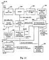
- RF transceiver 42, 42' operates on a frequency in the band from 902 to 928 MHz (Fig. 13).
- Transceiver 42, 42' includes a receiving section consisting of an RF amplifier 200 and a mixer 202, which is supplied with a 904.3 MHz signal from a local oscillator 210, in order to provide an intermediate frequency signal (IF) of 10.7 MHz.
- the IF signal is amplified by IF amplifier 204 and supplied to a detector and data splitter 206, which produces data signals compatible with a microprocessor 208.
- Microprocessor 208 is interconnected by data lines 39, 39' with the respective microcomputer 40, 40'.
- Transceiver 42, 42' additionally includes a transmitting section including local oscillator 210, which is modulated by a data output of microprocessor 208, and a power amplifier 212, whose output is connected with antenna 28, 30.
- Local oscillator 210 is stabilized by a phase-lock-loop frequency synthesizer 214, which receives a reference signal of 6.3 MHz from a frequency reference 216.
- Power amplifier 212 is keyed on and off from a solid-state power switch 220, which is powered from a solid-state switch 218 under the control of power management circuits 44, 44' through line 43, 43'. All of the circuit components making up transceiver 42, 42' are commonly available from numerous commercial sources.
- Keypad 36, 36' in the illustrated embodiment is a commercially available ten-digit membrane switch panel, which is marketed by Spectra Symbol Company of Salt Lake City, Utah. It is to be understood that input device 36 is not limited to a keypad but could be a voice recognition device, a digitizer pad, an alphanumeric keyboard, or other devices capable of receiving a user selection of a response.
- display 38, 38' is a commercially available 24-character by 2-line display. Such display is marketed by Optrex Company of Japan under Model No. DMC24227.
- the FM communication link between base unit 22 and remote response units 24 is a half-duplex channel in which a base data packet 50 is transmitted by system controller 26 to all remote response units 24, and response data packets 52 are transmitted from each keypad 24 to system controller 26 individually within a time slot that is assigned to each remote response unit.
- base data packet 50 and response data packet 52 have the same essential structure.
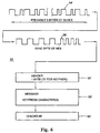
- Base data packet 50 and response data packet 52 each include a preamble 54, 54' composed of nine bytes of 55 hex, which identifies the transmission as a data packet (Figs. 5 and 6).
- the content of the preamble is sufficiently distinct to preclude false recognition resulting from various EMI sources.
- the preamble 54, 54' is followed by a sync byte 56, 56' which provides a timing mark for enabling the receiving units to be coordinated in their response intervals.
- the remaining portion of each data packet 50, 52 is made up of a HEADER 58, 58'; a MESSAGE 60, 60'; and a CHECKSUM 62, 62'.
- HEADER 58 may include a one-byte response character field 59, which identifies which of five groups of remote response units 24 are to transmit a response data packet in response to that base data packet. For large groups of response units, such as 250 units, it is convenient to divide the units into groups of, for example, 50 units. This provides flexibility in system deployment of various numbers of response units by eliminating the response intervals for phantom response units.
- Response character field 58' includes a 0 character in order to identify the data packet as a response data packet 52.
- HEADER 58 may additionally include a Response Length Byte 72, which instructs the remote response units of the number of characters to include in the MESSAGE field 60'. This allows the transmittal of responses longer than a single character under the control of the base unit. HEADER 58 may additionally include a Base Packet Length field to instruct the remote response units of the number of characters in the base data packet 50. This allows the transmitting of messages of various length globally to all response units in a Global Message field 76.
- MESSAGE field 60 includes a group of characters 64, 66, 68, and 70 that are individually pertinent to particular response units. The data in MESSAGE field 60 is structured so that each remote response unit is capable of identifying which character, or characters, pertains to that particular unit. However, the entire content of MESSAGE 60 is received by all remote response units and loaded into the memory thereof. Each individual remote response unit examines the character location or locations assigned to that particular unit and responds to the value of the character at that particular location.
- MESSAGE field 60 includes a data structure of Acknowledge Bit fields 64, which signify to the remote response units to which each bit pertains, whether the previous response data packet transmitted by that unit was validly received at system controller 26.
- a field of correct/incorrect flag bits 66 identify to each remote response unit whether the response contained in the previous response data packet entered by the user was correct or incorrect. The value of the correct/incorrect flag bit is set by computer 32 by comparing received responses with a correct answer key.
- MESSAGE field 60 additionally includes mike control bits 68. Each mike control bit 68 may be set by the instructor via computer 32 in response to a user requesting audio communication with the instructor by entering a defined response in keypad 36.
- Each mike control bit 68 is assigned to a particular remote response unit in a group of remote response units and, when set, is processed by microcomputer 40'.
- microcomputer 40' actuates audio transmitter 47 for that particular remote response unit in order to provide a one-way audio communication from the remote unit user to the instructor through audio receiver 47b in system controller 26 and a transceiver to the host site over a phone line 49.
- MESSAGE field 60 additionally includes a Group Identity byte 70 that may take on the value of between one and five.
- the group identity byte designates which of the groups of remote response units 24 the characters of MESSAGE field 60 pertain.
- the value of Group Identity byte 70 and MESSAGE field 60 advantageously, may be set to a different group than the Response Byte 59 in HEADER 58.
- base data packet 50 may set MESSAGE Group Identity byte 70 at the first group (group 1) and set the Response Byte 58 at a subsequent group (group 2) whereby the group that previously responded by transmitting a response data packet may be acknowledged during a subsequent transmission in order to power down the transceiver for the remote response unit that had previously transmitted a response data packet validly received by the base unit.
- MESSAGE field 60 may additionally include a Global Message field 76 containing characters which globally pertain to all, or a group of. remote response units 24.
- Global Message field 76 One application for Global Message field 76 is to download operating code to each microcomputer 40'. This avoids the necessity for hardware modifications to upgrade the operating software of each remote response unit 24.
- Another application for Global Message field 76 is in conjunction with correct/incorrect flag bits 66. Two, or more, messages could be carried in Global Message field 76, with microcomputer 40' programmed to read out one of the messages on display 38 if the correct/incorrect flag bit 66 is of a given value and a different message read-out if the flag bit is of a different value. In this manner, the student may be more thoroughly advised with respect to incorrect answers.
- Global Message field 76 has a capacity of 200 characters. Longer strings of code may be downloaded to each microcomputer 40' through a series of transmissions.
- CHECKSUM 62, 62' provides an error detection byte at the end of each base data packet or response data packet. This byte is set to the value of the least significant byte of the sum of all bytes in the respective data packet, in order to ensure that a valid reception of the packet is accomplished, as is understood by those of ordinary skill in the art.
- Response data packet 52 includes the response message, or key press character(s), in MESSAGE field 60'.
- the response in MESSAGE field 60' is a single character, which is produced by a single keystroke entered with keypad 36.
- the response in MESSAGE field 60' may be multiple characters in length, the number of characters either fixed or designated by Response Length Byte 72. This allows the system controller 26 to control the length of the response from response data packet 52.
- Microcomputer 40' in each remote response unit 24 responds to the value set in Response Length Byte 72 by assembling the response data packet 52 with the designated number of characters indicated by Response Length Byte 72. In this manner, responses composed of multiple character words may be collected by remote response system 20.
- microcomputer 40' makes up the response data packet 52 including a null entry in MESSAGE field 60' if the user has not entered a response with keypad 36.
- each response unit 24 transmits a response data packet in response to each base data packet transmitted by the base unit irrespective of whether or not a user has entered a response.
- the base unit may conduct diagnostics of each remote unit in order to determine if each remote unit is within a non-interfering communication range of the base unit.
- Each remote response unit 24 is assigned a unique identification number, or address. Each remote response unit may also be assigned to one of a plurality of groups which, in the illustrated embodiment, are designated groups 1-5. The identification number and group number are retained in response unit memory.
- each remote response unit determines, by calculation, the time interval following sync byte 56 when it is to respond. This calculation is based upon the position that the identification number for that remote response unit occupies in its group, as well as the value of base data packet length byte 74 and Response Length Byte 72. If no base data packet length byte or response length byte is utilized, a default value is used.
- base data packet 50 and response data packet 52 are assembled at respective system controller 26 and remote response unit 24 and frequency modulated at RF transceiver 42, 42'.
- the received FM transmission is received by the RF transceiver 42, 42' of the receiving unit, reduced in frequency and detected.
- the detected signal is an analog waveform having peaks and valleys that substantially conform to the transmitted data packet.
- the analog signal produced by the detector is further processed by a data slicer (not shown), which produces a waveform having better defined rise and fall points, and having an amplitude that is appropriate for processing by microprocessor 40, 40'.
- Microprocessor 40, 40' performs the final step in the decoding process by responding to the rising edges of the data stream provided from RF transceiver 40, 42' in order to identify 0-value bits and 1-value bits in a manner that will now be described.
- a 0-bit 80 is composed of an entire cycle of a square wave as measured from a rising edge 82 to the subsequent rising edge 82 (Fig. 3).
- the waveform cycle could be measured from the falling edge 84 to the subsequent falling edge (not shown).
- the advantage of this coding technique is that the interval between rising edges, or, alternatively, falling edges, of a transmitted data pulse is exceptionally constant whereas the interval between a rising edge 82 and a subsequent falling edge 84 is rather inconsistent and subject to environmental effects, such as signal strength and temperature.
- the length L 0 of the 0 bit is encoded at a predetermined time interval by the microprocessor 40, 40' toggling an output a predetermined repetition rate in order to generate the 0 bits.
- a 1-bit 86 is defined from its leading edge 88 to the leading edge 88 of the subsequent waveform.
- the waveform cycle has a time interval L 1 , which is much shorter than the interval L 0 for the 0-bit 80. This is accomplished by generating the 1 bit by the microprocessor 40, 40' toggling its output at a predetermined frequency that is higher than that utilized to generate the 0-bit 80.
- the encoded packet will vary in time duration as a function of the value of the respective bits 81 making up the packet (Fig. 3).
- data 81 is examined prior to encoding in order to determine whether the majority of the bits, in this case 0s, would be encoded according to the greatest length.
- the duration required to transmit data 81 would be exceptionally long.
- the data 81 is inverted to 81' whereby it is made up primarily of 1 bits which are encoded according to a shorter time length. In this manner, the length of the interval required to transmit data 81 is never longer than would be required to transmit a data word made up of 50 percent of its bits encoded according to the longest duration.
- a bit-decoding technique 90 is illustrated in Fig. 4.
- Microcomputer 40, 40' includes an internal counter, which counts the interval between rising edges of the bit-sliced data stream D provided from RF transceiver 42, 42'. The length of the interval, as defined in terms of the microcomputer counts is then compared with two distinct, non-overlapping ranges. A count must fall within one of the ranges in order to be decoded as a valid bit.
- a bit-count 92 is below the lower limit of one of the intervals and a bit count of 94 is greater than the limit of the same range. Accordingly, counts 92 and 94 would be deemed invalid unless they would fall within the other non-overlapping range, in which case the count would be decoded as the opposite bit.
- the remote response unit may be programmed to transmit a response data packet containing a null MESSAGE 60' if the user has not entered a response, the base unit 22 may advise the instructor that a particular remote response unit is out of range or is otherwise inoperable.
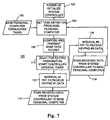
- System controller 26 includes a control program 100 (Fig. 7).
- Control program 100 is initialized at 102 upon powering up of controller 26.
- a routine 104 determines if personal computer 32 has formulated any tasks at 106 and responds to any formulated tasks.
- Program 100 then composes and transmits at 108 a base data packet 50 to all remote response units 24.
- the program then institutes a delay 110 of finite duration to allow the remote response units 24 to prepare their responses.
- the system controller 26 receives a response data packet from the first keypad designated to respond, decodes the response data packet, and passes the decoded data to base personal computer 32 at 114.
- the program then proceeds to the next interval at 116 and receives, decodes, and passes to personal computer 32 the response data packet from the next keypad at 118. After all of the intervals have been examined, the control returns to routine 104 in order to determine whether a new task has been ordered by computer 32.
- the software in instructor's computer 32 may formulate a task for system controller 26 to repetitively transmit base data packets until valid responses are received from all of the remote response units, or for a designated number of cycles, or a designated length of time. Accordingly, the routine defined by steps 108-118 may be repetitively carried out under the instructions of personal
- a control program 120 is repetitively carried out at each remote response unit 24 (Fig. 8).
- the program is initialized at 122 upon powering up of the unit and waits at 124 to receive a base data packet from system controller 26.
- the remote response unit examines the characters in the HEADER field 58 in order to determine whether that particular remote response unit is within the group specified by group designator 59 to respond, at 126.
- the particular remote response unit additionally examines the MESSAGE field 60 and determines from Group Identity byte 70 if the content of the message field pertains to the group of which that particular response unit is a member.
- Each response unit within the group designated by Group Identity byte 70 examines the Acknowledge Bit field 64, correct/incorrect flag bit 66, and mike control bits 68 that pertain to that particular unit within the group and responds to the values set for those particular bits. If the Acknowledge Bit field 64 for that particular unit is set, then the system controller 26 has validly received the previous response data packet sent by that particular response unit. If the correct/incorrect flag bit 66 is set to correct, microprocessor 40' may illuminate a "correct" indicator or an "incorrect” indicator (not shown) or may provide a particular indication on display 38.
- a correct indication could be made by illuminating only the uppermost horizontal segment of a seven-segment display composing display 38 and the incorrect indication could be the lowermost horizontal segment of display 38 or vice versa.
- the microcomputer 40' may respond to a value of the correct/incorrect flag bit by displaying on indicator 38 a portion of a Global Message field 76, which pertains to correct answers, or a different portion of Global Message field 76, which pertains to an incorrect answer. If mike control bit 68 for that particular remote response unit is set, microcomputer 40' responds by actuating audio transmitter 47a in order to allow one-way audio communication between the user's microphone 46' and the instructor.
- Remote response unit 24 additionally responds to the Response Length Byte 72 and the base data packet length byte 74 in order to determine appropriate interval timing, as set forth above.
- an interval timer is run at 128 and the control waits at 130 for the appropriate interval for that particular response unit to transmit.
- a response data packet is transmitted at 132 during the appropriate interval.
- Control program 100 initiates a transmission by system controller 26 by getting any task being requested from personal computer 32 at 104.
- the transmitting portion of RF transceiver 42 is actuated at 134.
- Preamble 54 is transmitted at 136 to all of the remote response units 24 for the purpose of stabilizing the data transferred from RF transceiver 42, RF transceiver 42' to each remote response unit.
- the data is allowed to stabilize because the detector portion of the RF transceiver has a finite stabilizing time interval.
- the sync byte 56, HEADER packet 58, MESSAGE packet 58 and CHECKSUM 62 are transmitted at 138.
- the transmitter is then turned off at 140 and an interval timer is started at 142.
- the interval timer matches response data packets from the remote response units 24 with each particular response unit, decodes the packets and makes the information available to personal computer 32.
- the system controller 26 receives keypad data under the control of program 100 by repetitively transmitting the base packet and monitoring subsequent intervals for response data packets from the response units (108, 110, 112, 116) (Fig. 10). The received response data packets are decoded and the data passed to computer 32 (114, 118). After an entire group of remote response units 24 have transmitted response data packets, system controller 26 compiles Acknowledge Bit field 64 at 144 from a validity test made of each received response data packet.
- each remote response unit 24 receives a base data packet from the system controller, at 124, over the RF link between antenna 28 and antenna 30 (Fig. 11).
- Microcomputer 40' decodes the received data and determines at 126 whether that remote response unit is in the group that is designated by Response Byte 59 to transmit a response and is in the group identified by Group Identity byte 70 for pertinence of MESSAGE field 60. If so, the characters in MESSAGE 60 that pertain to that particular remote response unit are extracted at 126. If the remote response unit is in the group designated by Response Byte 59 to transmit a response, microcomputer 40' then starts an interval timer and awaits the interval determined at 126 that is assigned to that particular response unit for responding.
- microcomputer 40' When that interval arrives, microcomputer 40' turns on RF transceiver 42' at 148 in order to stabilize the transmitter portion thereof and transmits preamble 54' in order to stabilize the data in transceiver 42 of system controller 26 at 150.
- Remote response unit 24 then transmits the sync byte 56', HEADER 58', MESSAGE character(s) 60' and CHECKSUM 62' to the system controller 26.
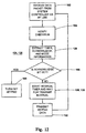
- Each remote response unit 24 receives the data packet from the system controller via RF link at 162 (Fig. 12). If all of the bits are decoded without a rejection, the CHECKSUM for the entire base data packet is verified at 164 in order to accept, or reject, the transmission. The timer, acknowledge, and mode information is extracted at 126 if the response unit is in the group designated by Group Identity Byte 70. It is then determined at 166 whether the aknowledge bit, which pertains to that particular remote response unit in Acknowledge Bit field 64, is set. If so, the transceiver 42' for that keypad is powered down at 168.
- microcomputer 40' If it is determined at 166 that the acknowledge bit for that particular remote response unit is not set and the remote response unit is in the group designated by Response Byte 59 to transmit a response, microcomputer 40' starts the interval timer at 128 and waits for the calculated transmit interval at 130. Remote response unit 24 transmits the response data packet at 132. If the remote response unit is not in the group designated by Response Byte 59 to transmit a response, microcomputer 44' will await its Response Byte 59 and then transmit a response data packet.
- a method 170 for transferring a large block of data to all remote response units in a time-effective manner is illustrated in Fig. 14.
- Method 170 is initiated by the personal computer associated with system controller 26 dividing the large block of data to be transferred into a multiple-packet data stream at 172.
- the multiple-packet data stream is passed at 174 to the system controller 26 and is transmitted in its entirety to all remote units at 176.
- Each remote response unit 24 decodes the multiple-packet data stream and determines whether each packet was accurately received.
- a bit map is formed in each remote response unit 24 of bits indicating which packets were accurately received.
- the system controller 26 transmits at 178 a central data packet 50 to all remote response units 24 formatted to request the bit map reports from all of the remote response units.
- a bit map master is formulated or updated at 180 in the system controller 26 from response data packets 52 encoded with the bit maps of the various remote response units.
- the system controller examines the master bit map at 182 and sends all packets corresponding to the packets which were not accurately received by even one remote response unit, as reflected in the master bit map.
- the bit maps of the individual remote response units are retrieved at 184 to reflect the additional accurately received data packets in the same manner as before.
- the master bit map is updated at 186, and it is determined at 188 whether the number of retries specified for obtaining 100 percent accurate packet data transmission has been reached. If not, another cycle 182, 184, 186 is repeated of sending missing packets, updating the bit maps at each remote response unit, and updating the master bit map.
- a message is sent to the base personal computer at 190.
- the instructor may request that additional retries be attempted or may provide a verbal instruction, to the users of the one or more remote response units which have not completely received the multiple-packet data accurately, to move to a different location in order to retry the process.
- the advantage of method 170 is that the time interval required to energize the transceivers 42' of all of the remote response units 24 after each of the data packets are transmitted is avoided. This time interval may be significant because it is multiplied by each of the keypads. By breaking the bulk transmission of data into multiple data packets, only the data packets that are not accurately received at all units, are retried. This avoids the necessity for having to retry the entire bulk data transfer if one or more remote response units do not accurately receive the entire transfer.
- the present invention provides a wireless remote response system that has exceptionally good noise immunity and a tolerance for variations in the timing of transmitted signals while ensuring a virtually error-free operation.
- the system provides exceptional flexibility by allowing the transmittal of message data from the base unit to the remote response units in the same base data packet that synchronizes the transmittal of the response data packets from the remote response units.
- different groups of response units which are divided into groups in order to accommodate a larger number of response units on a single RF link, may be designated by a base data packet to: (a) transmit a response data packet and (b) process the message data.
- the message data accommodates the disbursement of acknowledge bits, for validly received responses, in order to cause the acknowledged response units to stop transmitting.
- Correctness characters and microphone enable characters may additionally be transmitted in the message data and processed by the remote response units.
- the invention allows the downloading of a large field of characters globally to all of the remote response units in an efficient manner. This allows the displaying of lengthy feedback messages to the users, for example, in response to correct or incorrect answers, as well as the downloading of operating code for the individual remote response units and the downloading of code for other purposes.
- the ability of the base unit to instruct the remote response units of the length of the intended response from each of the remote response units, and the ability of the remote response units to respond to such designation by structuring a suitable response data packet allows the retrieval of responses that are more complex than a single character.
Claims (47)
- Verfahren zur Benutzung eines drahtlosen Systems der Abfrage von Antworten, die von mehreren Benutzern in mehrere Antworteinheiten (24) eingegeben sind, an einer Basiseinheit (22), enthaltend Übertragen über eine drahtlose Kommunikationsverbindung von der Basiseinheit zu den mehreren entfernten Antworteinheiten und Übertragen über eine drahtlose Kommunikationsverbindung von den Antworteinheiten zu der Basiseinheit jede Antwort, die von einem Benutzer eingegeben ist,
dadurch gekennzeichnet, daß das Verfahren ferner enthält Übertragen eines Datenpaketes von der Basiseinheit, das eine Zeitmarkierung (56,56') enthält, damit die entfernten Antworteinheiten in ihren Antwortintervallen koordiniert werden können, wobei das Basisdatenpaket aus mehreren Zeichen besteht, und wenigstens ein Teil dieser mehreren Zeichen verschiedene Antworteinheiten betreffen, Decodieren des Basisdatenpakets an den Antworteinheiten, Laden wenigstens eines Teils des dekodierten Basisdatenpakets an den Antworteinheiten in einen Speicher, Bestimmen jedes Zeichen an einzelnen Antworteinheiten, welches diese besondere Antworteinheit betrifft, und Verarbeiten jedes Zeichens durch die Antworteinheiten, das die besonderen Antworteinheiten betrifft. - Verfahren nach Anspruch 1, wobei die mehreren Zeichen Bestätigungszeichen (64) enthalten, die jeweils angeben, ob eine gültige Antwort zuvor von einer besonderen Antworteinheit empfangen wurde.
- Verfahren nach Anspruch 2, wobei das Verarbeiten jedes Zeichens die Beendigung der Übertragung einer Antwort enthält, die von einem Benutzer eingegeben wurde, in Reaktion auf ein Bestätigungszeichen, das diese besondere Antworteinheit betrifft.
- Verfahren nach Anspruch 1, wobei die mehreren Zeichen Fehlerfreiheitszeichen (66) enthalten, die jeweils angeben, ob eine zuvor empfangene Antwort mit einer korrekten Antwort in einem Antwortschlüssel übereinstimmt.
- Verfahren nach Anspruch 4, wobei der Teil des dekodierten Basisdatenpaktes eine weitere Mehrzahl von Zeichen enthält, die alle Antworteinheiten betreffen, wobei eine besondere Antworteinheit eine erste Nachricht anzeigt, die in der weiteren Mehrzahl der Zeichen enthalten ist, als Reaktion auf einen vorgegebenen Wert des Fehlerfreiheitzeichens, das die besondere Antworteinheit betrifft, und eine zweite Nachricht anzeigt, die in der weiteren Mehrzahl der Zeichen enthalten ist, als Antwort auf einen anderen Wert des Fehlerfreiheitzeichens, das diese besondere Antworteinheit betrifft.
- Verfahren nach Anspruch 4, wobei jede Antworteinheit den Wert des Fehlerfreiheitzeichens anzeigt, der diese besondere Antworteinheit betrifft.
- Verfahren nach Anspruch 1, wobei die mehreren Zeichen Mikrofonaktivierungszeichen (68) enthalten, wobei jede eine Audiokommunikationsverbindung mit einer bestimmten Antworteinheit aktiviert.
- Verfahren nach Anspruch 7, wobei die Antworteinheiten ein Mikrofon (46) und eine Audiokommunikationsverbindung (48) mit der Basiseinheit enthält und wobei eine besondere Antworteinheit die Audiokommunikationsverbindung zwischen dem Mikrofon der besonderen Antworteinheit und der Basiseinheit in Reaktion auf das Mikrofonaktivierungszeichen öffnet, daß diese besondere Antworteinheit betrifft.
- Verfahren nach Anspruch 1, wobei die entfernten Antworteinheiten in Gruppen unterteilt sind und wobei das dekodierte Basisdatenpaket eine Bezeichnung einer Gruppe von Antworteinheiten enthält, die die mehreren Zeichen betreffen.
- Verfahren nach Anspruch 1, wobei die entfernten Antworteinheiten in Gruppen unterteilt sind und wobei das dekodierte Basisdatenpaket eine erste Bestimmung einer besonderen Gruppe von Antworteinheiten enthält, die die mehreren Zeichen betreffen, und eine zweite Bestimmung einer besonderen Gruppe von Antworteinheiten, um ein Antwortdatenpaket zu übertragen.
- Verfahren nach Anspruch 1, wobei die entfernten Antworteinheiten in Gruppen unterteilt sind und wobei das decodierte Basisdatenpaket eine Bestimmung einer besonderen Gruppe von Antworteinheiten enthält, um ein Antwortdatenpaket zu übertragen.
- Verfahren nach Anspruch 11, enthaltend Bereitstellen einer eindeutigen Identifikation zu jeder der Anzahl der Antworteinheiten und Bestimmen eines Antwortintervalls bei jeder der Anzahl der Antworteinheiten nach dem Basisdatenpaket als Funktion der Bestimmung einer besonderen Gruppe von Antworteinheiten und der Identifikation einer besonderen Antworteinheit.
- Verfahren nach Anspruch 1 oder 12, wobei eine von einem Benutzer eingegebene Antwort in einem Antwortdatenpaket übertragen wird und wobei das dekodierte Basisdatenpaket eine Bestimmung der Anzahl von Zeichen enthält, die ein Antwortdatenpaket bildet.
- Verfahren nach Anspruch 13, wobei jede Antworteinheit ein Antwortdatenpaket überträgt, das die Anzahl von Zeichen enthält, die in dem dekodierten Basisdatenpaket bestimmt ist.
- Verfahren nach Anspruch 1, wobei jede der entfernten Anworteinheiten einen Mikrocomputer (40') enthält, der einen löschbaren Speicher enthält, und wobei der Teil des dekodierten Basisdatenpakets den Arbeitscode enthält und das Verarbeiten das Speichern des Arbeitscodes in dem löschbaren Speicher für den Betrieb des Mikrocomputers enthält.
- Verfahren nach Anspruch 1 oder 15, wobei eine von einem Benutzer eingegebene Antwort in einem Antwortdatenpaket übertragen wird und wobei das Übertragen einer Antwort das Übertragen eines Null-Antwortdatenpakets enthält, wenn ein Benutzer keine Antwort eingegeben hat.
- Verfahren nach Anspruch 1, wobei der Teil des dekodierten Basisdatenpakets mehrere Zeichen enthält, die global eine Vielzahl von entfernten Antworteinheiten betreffen.
- Verfahren nach Anspruch 17, enthaltend die Übertragung einer Mehrzahl von Basisdatenpaketen, die jeweils eine Mehrzahl von Zeichen enthalten, die global eine Mehrzahl von entfernten Antworteinheiten betreffen, Bestimmen an jeder entfernten Antworteinheit, welches der Basisdatenpaketen gültig empfangen worden ist und Übertragen von jeder entfernten Antworteinheiten eine Anzeige, welches der Basisdatenpakete gültig an der besonderen Antworteinheit empfangen wurde.
- Verfahren nach Anspruch 18, ferner enthaltend das Assemblieren eines Bitmap an der Basiseinheit von allen Basisdatenpaketen, die gültig an den entfernten Antworteinheiten empfangen wurden, und wiederholtes Rückübertragen eines der Basisdatenpakete, von dem das Bitmap anzeigt, daß es nicht gültig an wenigsten einer der entfernten Antworteinheiten empfangen wurde.
- Verfahren nach Anspruch 1, wobei eine von einem Benutzer eingegebene Antwort in einem Antwortdatenpaket übertragen wird und wobei das Antwortdatenpaket Mehrfachzeichenantworten enthält.
- Verfahren nach Anspruch 20, enthaltend das Kodieren von Daten des Datenpakets durch Variieren der Zeitspanne für wenigstens einen Zyklus einer periodischen Wellenform eines übermittelten Signals, um einen Wert eines Bit zu kodieren, und Dekodieren der Daten durch Messen von Zeitintervallen für wenigstens einen Zyklus des empfangenes Signals und Bestimmen, ob jedes der Zeitintervalle in eine von wenigstens zwei bestimmten, nicht-überlappenden Zeitspannen fällt.
- Verfahren nach Anspruch 21, wobei das Kodieren das Bestimmen enthält, ob eine Mehrzahl von Bits in dem Datenpaket einen Wert haben, der für eine längere Zeitspanne kodiert wäre und Invertieren dieser Bits in diesem Datenpaket vor dem Kodieren, um die erforderliche Zeit zu reduzieren, um ein Datenpaket zu übertragen.
- Verfahren nach Anspruch 22, enthaltend das Übertragen einer Anzeige, daß die Bits in einem Datenpaket invertiert worden sind.
- Drahtloses Fernantwortsystem, enthaltend:dadurch gekennzeichnet, daß die Basiseinheit ein Basisdatenpaket übertragen kann, das eine Zeitmarkierung enthält, so daß die entfernten Antworteinheiten in ihren Antwortintervallen koordiniert werden können, daß das Basisdatenpaket aus einer Mehrzahl von Zeichen besteht, von denen wenigstens ein Teil verschiedene Antworteinheiten betrifft, und daß die Antworteinheiten in der Lage sind, das Basisdatenpaket zu dekodieren, wenigstens einen Teil des dekodierten Basisdatenpakets an der Antworteinheit in einen Speicher zu laden und an einzelnen Antworteinheiten jedes Zeichen zu bestimmen, das die besonderen Antworteinheiten betrifft und jedes Zeichen zu verarbeiten, das die besonderen Antworteinheiten betrifft.eine Basiseinheit (22), mehrere Antworteinheiten (24) und eine drahtlose Kommunikationsverbindung zwischen der Basiseinheit und den Antw.orteinheiten, wobei die Basiseinheit betätigbar ist, um Daten zu den Antworteinheiten über die Kommunikationsverbindung zu übertragen und die Antworteinheiten betätigbar sind, um an die Basiseinheit über die Kommunikationsverbindung jede Antwort zu übertragen, die von einem Benutzer eingegeben ist,
- System nach Anspruch 24, wobei die mehreren Zeichen Bestätigungszeichen (64) enthalten, die jeweils anzeigen, ob die Basiseinheit ein gültiges Antwortdatenpaket von einer besonderen Antworteinheit enthalten kann.
- System nach Anspruch 24, enthaltend
einen ersten Mikrocomputer (40) in der Basiseinheit, der programmiert ist, um ein Basisdatenpaket zu assemblieren, dieses Basisdatenpaket zu kodieren und das kodierte Basisdatenpaket über die Verbindungsleitung den mehreren entfernten Antworteinheiten mitzuteilen,
einen zweiten Mikrocomputer (40') in jedem der entfernten Antworteinheiten, der programmiert ist, um ein Basisdatenpaket, das von der Basiseinheit empfangen wurde, zu dekodieren, einen Teil des dekodierten Basisdatenpakets in einen Speicher zu laden und jedes Zeichen dieses Teils des dekodierten Basispakets, das diese besondere Antworteinheit betrifft, zu bestimmen,
eine Eingabeeinrichtung in jedem der entfernten Antworteinheiten zum Empfang einer Benutzerantwortauswahl,
wobei der zweite Mikrocomputer programmiert ist, um jedes Zeichen zu verarbeiten, das in dem Speicher diese besondere Antworteinheit betrifft und um ein Antwortdatenpaket in Reaktion auf einen Benutzer zu assemblieren und einer Auswahl in die Eingabeeinrichtung einzubringen, das Antwortdatenpaket zu kodieren und das kodierte Antwortdatenpaket über die drahtlose Kommunikationsleitung von der besonderen Antworteinheit zu der Basiseinheit zu übermitteln,
und wobei der erste Mikrocomputer programmiert ist, um die Antwortdatenpakete, die von jeder der Antworteinheiten empfangen wurden, zu dekodieren. - System nach Anspruch 26, wobei der zweite Mikocomputer pogrammiert ist, die Übertragung eines Antwortdatenpakets nicht fortzusetzen, wenn der zweite Mikrocomputer geeignet ist, ein Bestätigungzeichen in dem Teil des dekodierten Basisdatenpakets zu bestimmen, das diese besondere Antworteinheit betrifft.
- System nach Anspruch 24, wobei die mehreren Zeichen Fehlerfreiheitszeichen (66) enthalten, die jeweils anzeigen, ob eine zuvor empfangene Antwort mit einer korrekten Antwort in einem Antwortschlüssel übereinstimmt.
- System nach Anspruch 28, wobei der Teil des dekodierten Basisdatenpakets eine weitere Mehrzahl von Zeichen enthält, die alle Antworteinheiten betreffen, wobei der zweite Mikrocomputer einer besonderen Antworteinheit programmiert ist, eine erste Nachricht anzuzeigen, die in der weiteren Mehrzahl von Zeichen enthalten ist, in Reaktion auf einen vorgegebenen Wert des Fehlerfreiheitszeichens, das die besondere Antworteinheit betrifft, und eine zweite Nachricht anzuzeigen, die in der weiteren Mehrzahl von Zeichen enthalten ist, in Reaktion auf einen anderen Wert des Fehlerfreiheitszeichens, das diese besondere Antworteinheit betrifft.
- System nach Anspruch 28, wobei der zweite Mikrocomputer in jeder Antworteinheit programmiert ist, um den Wert des Fehlerfreiheitzeichens anzuzeigen, das die besondere Antworteinheit betrifft.
- System nach Anspruch 24, wobei die mehreren Zeichen ein Mikrofonaktivierungszeichen enthalten, jedes zum Aktivieren eines Audiokommunikationskanals mit einer besonderen Antworteinheit.
- System nach Anspruch 31, wobei die Antworteinheiten ein Mikrofon und einen Audiokommunikationskanal (48) mit einer Basisstation enthalten und wobei der zweite Mikrocomputer einer besonderen Antworteinheit betätigbar ist, um den Audiokommunikationskanal zwischen dem Mikrofon der besonderen Antworteinheit und der Basisstation in Reaktion auf das Mikrofonaktivierungszeichen, das die besondere Antworteinheit betrifft, zu öffnen.
- System nach Anspruch 24, wobei die entfernten Antworteinheiten in Gruppen unterteilt sind und wobei das dekodierte Basisdatenpaket eine Bestimmung einer Gruppe von Antworteinheiten enthält, die die mehreren Zeichen betreffen.
- System nach Anspruch 24, wobei die entfernten Antworteinheiten in Gruppen unterteilt sind und wobei das dekodierte Basisdatenpaket eine erste Bestimmung einer Gruppe von Antworteinheiten enthält, die die mehreren Zeichen betreffen und eine zweite Bestimmung einer Gruppe von Antworteinheiten, um Antwortdatenpakete zu übertragen.
- System nach Anspruch 26, wobei die entfernten Antworteinheiten in Gruppen unterteilt sind und wobei das dekodierte Basisdatenpaket eine Bestimmung einer Gruppe von Antworteinheiten enthält, um Antwortdatenpakete zu übertragen.
- System nach Anspruch 35, wobei jeder der Antworteinheiten eine eindeutige Identifikation zugeordnet ist, und wobei der zweite Mikrocomputer programmiert ist, um ein Antwortintervall nachfolgend dem Basisdatenpaket zu bestimmen, in dem die zugehörige Antworteinheit ein Antwortdatenpaket als eine Funktion der Bestimmung einer besonderen Gruppe von Antworteinheiten und der eindeutigen Identifikation einer besonderen Antworteinheit zu übertragen hat.
- System nach Anspruch 26, wobei das dekodierte Basisdatenpaket eine Bestimmung einer Anzahl von Zeichen enthält, die das Basisdatenpaket bilden, und wobei der zweite Mikrocomputer betätigbar ist, um das Antwortintervall als eine Funktion der Anzahl von Zeichen zu bestimmen.
- System nach Anspruch 26, wobei das dekodierte Basisdatenpaket eine Bestimmung der Anzahl von Zeichen enthält, die das Antwortdatenpaket bilden, und wobei der zweite Mikrocomputer programmiert ist, um ein Antwortdatenpaket, das die Anzahl von Zeichen hat, zu assemblieren.
- System nach Anspruch 26, wobei der Teil des dekodierten Basisdatenpakets den Arbeitscode enthält und wobei der zweite Mikrocomputer programmiert ist, den Arbeitscode im Speicher zur Benutzung beim Betrieb des zweiten Mikrocomputers zu speichern.
- System nach Anspruch 26, wobei der zweite Mikrocomputer programmiert ist, ein Null-Antwortdatenpaket zu assemblieren, das keine Auswahl enthält, wenn ein Benutzer keine Auswahl eingegeben hat, das Null-Antwortdatenpaket zu kodieren und das kodierte Null-Antwortdatenpaket über die drahtlose Kommunikationsleitung von der besonderen Antworteinheit zu der Basiseinheit zu übertragen.
- System nach Anspruch 24, wobei das Antwortdatenpaket Benutzerselektionen enthält, die aus einer Mehrzahl von Zeichen bestehen.
- System nach Anspruch 26, wobei jeder der ersten und zweiten Mikrocomputer programmiert ist, um das jeweilige Datenpaket zu kodieren, indem die Zeitspanne entweder zwischen aufeinanderfolgenden ansteigenden Rändern oder zwischen aufeinanderfolgenden abfallenden Rändern einer periodischen Wellenform variiert werden, um einen Wert eines jeden Bit zu kodieren, der das Datenpaket bildet, und um das jeweilige Datenpaket durch Messen von Zeitintervallen entweder zwischen aufeinanderfolgenden ansteigenden Rändern oder zwischen aufeinanderfolgenden abfallenden Rändern eines empfangenen Signals zu decodieren.
- System nach Anspruch 42, wobei jeder der ersten und zweiten Mikrocomputer ferner programmiert ist, um zu bestimmen, ob jedes gemessene Zeitintervall in einem von wenigstens zwei kenntlichen, nicht überlappenden Zeitbereichen fällt, um einen Wert eines jeden Bits zu dekodieren.
- System nach Anspruch 42, wobei jeder der ersten und zweiten Mikrocomputer programmiert ist, um zu bestimmen, ob eine Mehrzahl von Bits in einem Datenpaket einen Wert haben, der über eine längere Zeitspanne kodiert würde und um die Bits des Datenpakets vor dem kodieren zu invertieren, um die Zeit zu reduzieren, die erforderlich ist, um ein Datenpaket zu übertragen.
- System nach Anspruch 44, wobei jeder der ersten und zweiten Mikrocomputer programmiert ist, um eine Anzeige zu übertragen, daß die Bits in einem Datenpaket invertiert worden sind.
- System nach Anspruch 26, wobei der erste Mikrocomputer programmiert ist, eine Mehrzahl von Basisdatenpaketen zu assemblieren, zu kodieren und zu übertragen, die jeweils mehrere Zeichen enthalten, die global eine Mehrzahl von entfernten Antworteinheiten betreffen, und wobei jeder zweite Mikrocomputer der Mehrzahl von entfernten Antworteinheiten programmiert ist, zu bestimmen, welches der Basisdatenpakete gültig empfangen wurde, und um ein Antwortdatenpaket zu assemblieren, zu kodieren und zu übertragen, einschließlich den Anzeigen, welche Basisdatenpakete an der entfernten Antworteinheit gültig empfangen wurden.
- System nach Anspruch 46, wobei der erste Mikrocomputer programmiert ist, ein Bitmap von den Antwortdatenpaketen zu assemblieren und wiederholt diejenigen der Basisdatenpakete zurückzuübertragen, von denen das Bitmap anzeigt, daß sie nicht gültig empfangen wurden.
Applications Claiming Priority (2)
| Application Number | Priority Date | Filing Date | Title |
|---|---|---|---|
| US08/265,843 US5724357A (en) | 1992-01-28 | 1994-06-24 | Remote response system and data transfer protocol |
| US265843 | 1994-06-24 |
Publications (4)
| Publication Number | Publication Date |
|---|---|
| EP0697773A2 EP0697773A2 (de) | 1996-02-21 |
| EP0697773A3 EP0697773A3 (de) | 1997-05-21 |
| EP0697773B1 true EP0697773B1 (de) | 2002-09-11 |
| EP0697773B2 EP0697773B2 (de) | 2008-06-25 |
Family
ID=23012091
Family Applications (1)
| Application Number | Title | Priority Date | Filing Date |
|---|---|---|---|
| EP95304487A Expired - Lifetime EP0697773B2 (de) | 1994-06-24 | 1995-06-26 | Verfahren zum Sammeln von Zuhörerreaktionen und Datenübertragungsprotokoll |
Country Status (3)
| Country | Link |
|---|---|
| US (1) | US5724357A (de) |
| EP (1) | EP0697773B2 (de) |
| DE (2) | DE69528126T3 (de) |
Cited By (10)
| Publication number | Priority date | Publication date | Assignee | Title |
|---|---|---|---|---|
| US7330716B2 (en) | 2005-01-21 | 2008-02-12 | Responsive Innovations, Llc | Wireless communication system |
| US7502855B2 (en) | 2005-06-27 | 2009-03-10 | Renaissance Learning, Inc. | Wireless classroom system allowing user to access a particular classroom by selecting corresponding network from a list of wireless networks |
| CN1902820B (zh) * | 2003-11-07 | 2010-06-09 | 贝克休斯公司 | 电传信号系统 |
| US8041347B2 (en) | 2005-01-21 | 2011-10-18 | Responsive Innovations, Llc | Transmitter controlled communication links |
| US8549552B2 (en) | 2009-11-03 | 2013-10-01 | The Nielsen Company (Us), Llc | Methods and apparatus to monitor media exposure in vehicles |
| US8559918B2 (en) | 2011-05-27 | 2013-10-15 | The Nielsen Company (Us), Llc. | Methods and apparatus to associate a mobile device with a panelist profile |
| US8799054B2 (en) | 2005-12-20 | 2014-08-05 | The Nielsen Company (Us), Llc | Network-based methods and systems for initiating a research panel of persons operating under a group agreement |
| US8818901B2 (en) | 2006-06-02 | 2014-08-26 | The Nielsen Company (Us), Llc | Digital rights management systems and methods for audience measurement |
| US9426525B2 (en) | 2013-12-31 | 2016-08-23 | The Nielsen Company (Us), Llc. | Methods and apparatus to count people in an audience |
| US9551588B2 (en) | 2014-08-29 | 2017-01-24 | The Nielsen Company, LLC | Methods and systems to determine consumer locations based on navigational voice cues |
Families Citing this family (86)
| Publication number | Priority date | Publication date | Assignee | Title |
|---|---|---|---|---|
| US6021119A (en) * | 1994-06-24 | 2000-02-01 | Fleetwood Group, Inc. | Multiple site interactive response system |
| FR2734657B1 (fr) * | 1995-05-23 | 1997-07-04 | Thomson Multimedia Sa | Procede et dispositif de reception de signaux issus d'une pluralite d'emetteurs |
| JPH10511247A (ja) * | 1995-06-19 | 1998-10-27 | インターナシヨナル・ビジネス・マシーンズ・コーポレーシヨン | 単方向ブロードキャスト・システムにおいてデータ・パケットを受信するための方法及びシステム |
| JPH09261169A (ja) * | 1996-03-21 | 1997-10-03 | Sony Corp | 通信システム、通信システムの基地局、通信システムの携帯通信端末 |
| FR2753855B1 (fr) * | 1996-09-23 | 1998-11-06 | Systeme electronique interactif de messagerie | |
| US6151531A (en) * | 1996-12-12 | 2000-11-21 | Charles Frankel Et Al | System and method for managing the alteration of garments |
| US6289222B1 (en) * | 1997-07-16 | 2001-09-11 | The Hong Kong University Of Science & Technology | Free-forming one-way network |
| US6467089B1 (en) * | 1997-12-23 | 2002-10-15 | Nielsen Media Research, Inc. | Audience measurement system incorporating a mobile handset |
| FR2775820A1 (fr) * | 1998-03-03 | 1999-09-10 | Elti | Procede et systeme permettant d'analyser, rapidement, a distance, le profil de personnes interrogees, notamment le niveau de leurs connaissances |
| FR2782593B1 (fr) * | 1998-08-21 | 2000-11-24 | Sur Le Champ | Systeme d'aide a la gestion de reunions d'un groupe de personnes et terminal et poste central pour ce systeme |
| US6181910B1 (en) * | 1998-09-03 | 2001-01-30 | David A. Jerrold-Jones | Portable automated test scoring system and method |
| US6020810A (en) * | 1998-10-22 | 2000-02-01 | Har-Even; Eva A. | Automatic electronic date/mate finder and method of electronically finding a date/mate |
| US6665000B1 (en) | 1998-11-13 | 2003-12-16 | Fleetwood Group, Inc. | Remote site interactive system |
| US6760748B1 (en) * | 1999-01-20 | 2004-07-06 | Accenture Llp | Instructional system grouping student terminals |
| US6657550B1 (en) | 1999-10-12 | 2003-12-02 | Steve Flinn | Wireless lock-out system, apparatus and method for using the same |
| JP2003529822A (ja) * | 1999-12-22 | 2003-10-07 | イースピード, インコーポレイテッド | 商取引インターフェースを提供するためのシステムおよびその方法 |
| US6400289B1 (en) * | 2000-03-01 | 2002-06-04 | Hughes Electronics Corporation | System and method for performing lossless data compression and decompression |
| US7212988B1 (en) | 2000-07-26 | 2007-05-01 | Feldten Guy W | Test screening of videos |
| WO2002013163A2 (en) * | 2000-08-03 | 2002-02-14 | Lyda Edwin L | Apparatus for remote learning system |
| US7248888B2 (en) * | 2000-09-06 | 2007-07-24 | Eric Inselberg | Method and apparatus for interactive audience participation at a live entertainment event |
| US6434398B1 (en) * | 2000-09-06 | 2002-08-13 | Eric Inselberg | Method and apparatus for interactive audience participation at a live spectator event |
| US6996413B2 (en) * | 2000-09-06 | 2006-02-07 | Eric Inselberg | Method and apparatus for interactive audience participation at a live spectator event |
| US7792539B2 (en) * | 2000-09-06 | 2010-09-07 | Eric Inselberg | Method and apparatus for interactive audience participation at a live entertainment event |
| US9143828B2 (en) | 2000-09-06 | 2015-09-22 | Frank Bisignano | Method and apparatus for interactive audience participation at a live entertainment event |
| US7587214B2 (en) | 2000-09-06 | 2009-09-08 | Inselberg Interactive, Llc | Method and apparatus for interactive participation at a live entertainment event |
| US6760595B2 (en) | 2000-09-06 | 2004-07-06 | Eric Inselberg | Method and apparatus for interactive audience participation at a live spectator event |
| US7263378B2 (en) * | 2000-09-06 | 2007-08-28 | Eric Inselberg | Method and apparatus for interactive audience participation at a live entertainment event |
| US7797005B2 (en) * | 2000-09-06 | 2010-09-14 | Eric Inselberg | Methods, systems and apparatus for interactive audience participation at a live entertainment event |
| US20100306064A1 (en) * | 2000-09-06 | 2010-12-02 | Eric Inselburg | Method, system and apparatus for interactive billboard advertising at a live entertainment event |
| US20020143415A1 (en) * | 2001-03-28 | 2002-10-03 | Buehler William S. | Wireless audio and data interactive system and method |
| US8352582B2 (en) * | 2001-06-28 | 2013-01-08 | Koninklijke Philips Electronics N.V. | Temporal proximity to verify physical proximity |
| DE10138217A1 (de) * | 2001-08-03 | 2003-03-20 | Atmel Germany Gmbh | Verfahren zur Übertragung von Daten |
| JP3687785B2 (ja) * | 2001-08-15 | 2005-08-24 | 株式会社日本統計事務センター | 採点処理方法および採点処理システム |
| US6754602B1 (en) * | 2001-09-07 | 2004-06-22 | International Valvue Company | Wireless emergency lighting system |
| US10354322B2 (en) * | 2001-10-18 | 2019-07-16 | Bgc Partners, Inc. | Two sided trading orders |
| US6895213B1 (en) | 2001-12-03 | 2005-05-17 | Einstruction Corporation | System and method for communicating with students in an education environment |
| US20030180699A1 (en) * | 2002-02-26 | 2003-09-25 | Resor Charles P. | Electronic learning aid for teaching arithmetic skills |
| US20090155752A1 (en) * | 2002-02-26 | 2009-06-18 | Charles Pillsbury Resor | Non-right justification display system and method for displaying arithmetic equations |
| CH705435B1 (de) * | 2002-04-12 | 2013-03-15 | Synegration Ag | Elektronisches Abstimmungsverfahren und drahtloses Abstimmungssystem. |
| US20030215780A1 (en) * | 2002-05-16 | 2003-11-20 | Media Group Wireless | Wireless audience polling and response system and method therefor |
| US6964372B1 (en) | 2002-08-13 | 2005-11-15 | Peterson William M | Conference-table-based wired information system |
| GB2392056B (en) | 2002-08-15 | 2007-03-21 | Iml Ltd | A participant response system and method |
| US7222071B2 (en) | 2002-09-27 | 2007-05-22 | Arbitron Inc. | Audio data receipt/exposure measurement with code monitoring and signature extraction |
| US9646311B2 (en) * | 2003-02-04 | 2017-05-09 | First Principles, Inc. | Electronic course evaluation |
| US7599703B2 (en) * | 2003-05-12 | 2009-10-06 | Fleetwood Group, Inc. | Wireless polling system using spread-spectrum communication |
| CA2543017C (en) | 2003-10-17 | 2013-11-26 | Nielsen Media Research, Inc. | Portable multi-purpose audience measurement system |
| US20050238260A1 (en) * | 2004-04-16 | 2005-10-27 | Dave Coleman | Image and optical mark scanner with encryption |
| US20050237580A1 (en) * | 2004-04-16 | 2005-10-27 | Dave Coleman | Scanner read head for images and optical mark recognition |
| US8498567B2 (en) * | 2004-04-23 | 2013-07-30 | Alchemy Training Systems, Inc. | Multimedia training system and apparatus |
| US20050244803A1 (en) * | 2004-04-28 | 2005-11-03 | Interactive Learning Technologies, Llc | Classroom polling system |
| GB2415555B (en) * | 2004-06-26 | 2008-05-28 | Plus Design Ltd | Signalling method |
| US20060041615A1 (en) * | 2004-08-05 | 2006-02-23 | Remy Blank | Wireless delegate information and communication device, method and system |
| US8340059B2 (en) * | 2004-10-04 | 2012-12-25 | Fleetwood Group, Inc. | Response system and method with dynamic personality assignment |
| US8254310B2 (en) * | 2007-06-19 | 2012-08-28 | Fleetwood Group, Inc. | Audience response system and method with multiple base unit capability |
| EP1803308A4 (de) * | 2004-10-04 | 2012-10-24 | Fleetwood Group Inc | Antwortsystem und verfahren mit dynamischer personalitätszuweisung |
| DE102005001711A1 (de) * | 2005-01-13 | 2006-07-27 | Trw Automotive Gmbh | Elektroniksystem insbesondere für Fahrzeuge und Verfahren zur Reduzierung der Auswirkung elektromagnetischer Strahlung auf Elektroniksysteme in Fahrzeugen |
| US7533813B2 (en) * | 2005-04-21 | 2009-05-19 | Iml Limited | Wireless voting method |
| US7924759B1 (en) * | 2005-08-08 | 2011-04-12 | H-Itt, Llc | Validation method for transmitting data in a two-way audience response teaching system |
| US7286498B1 (en) * | 2005-08-09 | 2007-10-23 | H-Itt, Llc | Validation method and data structures for wireless communications |
| US7747261B2 (en) | 2005-08-18 | 2010-06-29 | Fleetwood Group, Inc. | Asynchronous response system with acknowledge |
| US20070298404A1 (en) * | 2006-06-09 | 2007-12-27 | Training Masters, Inc. | Interactive presentation system and method |
| US7677576B2 (en) * | 2006-06-13 | 2010-03-16 | Elliott A. Rudell | Electronic last-to-answer timed response game |
| US20080108298A1 (en) * | 2006-11-07 | 2008-05-08 | Selen Mats A | Certified two way source initiated transfer |
| RU2477570C2 (ru) * | 2007-01-10 | 2013-03-10 | СМАРТ Текнолоджиз ЮЭлСи | Система для ответного реагирования участников с эффективным использованием полосы частот |
| NZ578028A (en) * | 2007-01-10 | 2012-08-31 | Smart Technologies Ulc | Participant response system with question authoring/editing facility |
| JPWO2008096396A1 (ja) * | 2007-02-02 | 2010-05-20 | パナソニック株式会社 | 無線通信装置および暗号鍵更新方法 |
| US20080227080A1 (en) * | 2007-03-14 | 2008-09-18 | Gekl Technologies, Inc. | Student assessment system |
| US8358964B2 (en) * | 2007-04-25 | 2013-01-22 | Scantron Corporation | Methods and systems for collecting responses |
| US8270894B2 (en) * | 2007-06-15 | 2012-09-18 | Albert Hall Meetings, Ltd. | Response and communication system and method for interacting with and between audience members |
| US20100087139A1 (en) * | 2008-10-03 | 2010-04-08 | Fleetwood Group, Inc. | Audience response device, method, and system |
| US20110086330A1 (en) * | 2009-10-14 | 2011-04-14 | Mounia D Anna Cherie | Ethnic awareness education game system and method |
| US8356068B2 (en) | 2010-01-06 | 2013-01-15 | Alchemy Systems, L.P. | Multimedia training system and apparatus |
| CN102763148A (zh) | 2010-01-20 | 2012-10-31 | 桑福德有限合伙人公司 | 可动态配置的观众响应系统 |
| WO2011094214A1 (en) * | 2010-01-29 | 2011-08-04 | Scantron Corporation | Data collection and transfer techniques for scannable forms |
| US8514071B2 (en) | 2010-07-28 | 2013-08-20 | Versus Technology, Inc. | Real-time method and system for locating a mobile object or person in a tracking environment |
| US8310364B2 (en) | 2010-07-28 | 2012-11-13 | Versus Technology, Inc. | Real-time method and system for determining and validating location of a relocated mobile object or person in a tracking environment |
| US8271011B2 (en) * | 2010-08-04 | 2012-09-18 | Turning Technologies, Llc | Audience response system bulk data communication |
| US9912801B1 (en) | 2011-01-28 | 2018-03-06 | Kevin G. Adkins | Audience response system and method of use |
| US9537324B2 (en) | 2011-12-14 | 2017-01-03 | Fleetwood Group, Inc. | Audience response system with batteryless response units |
| US9219559B2 (en) | 2012-05-16 | 2015-12-22 | The Nielsen Company (Us), Llc | Methods and systems for audience measurement |
| CN102750845A (zh) * | 2012-06-21 | 2012-10-24 | 东北大学 | 一种互动教学系统及方法 |
| EP2902993A1 (de) | 2014-01-29 | 2015-08-05 | Provadis Partner für Bildung und Beratung GmbH | Drahtloses Lehrsystem |
| CN104008676A (zh) * | 2014-05-13 | 2014-08-27 | 郭伟 | 实时交互教学技术 |
| CN105468551A (zh) * | 2014-09-09 | 2016-04-06 | 北大方正集团有限公司 | 同步演示的控制系统和同步演示的控制方法 |
| US9667303B2 (en) * | 2015-01-28 | 2017-05-30 | Lam Research Corporation | Dual push between a host computer system and an RF generator |
| JP6390518B2 (ja) * | 2015-05-29 | 2018-09-19 | 京セラドキュメントソリューションズ株式会社 | 情報処理装置 |
Citations (14)
| Publication number | Priority date | Publication date | Assignee | Title |
|---|---|---|---|---|
| US3245157A (en) * | 1963-10-04 | 1966-04-12 | Westinghouse Electric Corp | Audio visual teaching system |
| US3314172A (en) * | 1965-06-15 | 1967-04-18 | Robert E Boyett | Testing systems |
| GB1078926A (en) * | 1965-06-24 | 1967-08-09 | Ml Aviation Co Ltd | Improvements relating to trolleys |
| US3416243A (en) * | 1965-04-19 | 1968-12-17 | Gen Electronic Lab Inc | Responding apparatus |
| US3445815A (en) * | 1965-09-27 | 1969-05-20 | Motorola Inc | Central to remote station signalling system |
| US3491464A (en) * | 1967-01-23 | 1970-01-27 | Raytheon Education Co | Teaching system |
| US4048729A (en) * | 1976-03-11 | 1977-09-20 | Fleetwood Furniture Company | Electrical teaching system |
| GB1523753A (en) * | 1974-09-16 | 1978-09-06 | Rai Radiotelevisione Italiana | Two-way data transmission system for cable television network |
| US4238893A (en) * | 1977-11-08 | 1980-12-16 | Sony Corporation | Signal transmission in teaching system |
| US5002491A (en) * | 1989-04-28 | 1991-03-26 | Comtek | Electronic classroom system enabling interactive self-paced learning |
| US5093786A (en) * | 1989-01-27 | 1992-03-03 | Fleetwood Furniture Company, Inc. | Remote response system |
| US5101406A (en) * | 1989-08-24 | 1992-03-31 | Telesystems Slw Inc. | Wireless communications system |
| US5273437A (en) * | 1991-06-27 | 1993-12-28 | Johnson & Johnson | Audience participation system |
| US5379213A (en) * | 1992-01-28 | 1995-01-03 | Fleetwood Furniture Company, Inc. | Test scoring system and method |
Family Cites Families (70)
| Publication number | Priority date | Publication date | Assignee | Title |
|---|---|---|---|---|
| US2352634A (en) * | 1938-07-18 | 1944-07-04 | Maury I Hull | Signaling system |
| GB1078296A (en) * | 1964-10-29 | 1967-08-09 | Modern Telephones Great Britai | Improvements in or relating to return speech paging systems |
| US3401469A (en) * | 1966-04-21 | 1968-09-17 | John A. Shaver | Educational system with mobile student learning stations |
| US3454718A (en) * | 1966-10-03 | 1969-07-08 | Xerox Corp | Fsk transmitter with transmission of the same number of cycles of each carrier frequency |
| US3500559A (en) * | 1967-09-11 | 1970-03-17 | Gen Electric | Electronic system for accepting and processing responses to questions presented to students |
| BE792678Q (fr) * | 1968-06-20 | 1973-03-30 | Koos Eugenia M | Systeme de television educatif |
| SE325160B (de) * | 1968-12-09 | 1970-06-22 | G Westerberg | |
| US3579864A (en) * | 1969-03-04 | 1971-05-25 | Sheldon Littwin | Teaching device |
| US3676939A (en) * | 1970-04-17 | 1972-07-18 | Edaids Inc | Student responder teaching device |
| US3757035A (en) * | 1970-04-21 | 1973-09-04 | Skiatron Elect & Tele | Interrogated transponder system |
| US3676580A (en) * | 1970-06-01 | 1972-07-11 | Video Information Systems | Interrogated transponder system |
| US3715510A (en) * | 1970-09-25 | 1973-02-06 | Computer Instr Corp | Method and apparatus for handling data from a plurality of channels |
| US3623242A (en) * | 1970-10-15 | 1971-11-30 | Duncan Electric Co Inc | Electronic teaching system |
| US3803491A (en) * | 1971-05-26 | 1974-04-09 | Tocom | Communications system |
| US3737858A (en) * | 1971-07-13 | 1973-06-05 | Advanced Research Corp | Versatile telemetering system |
| US3769579A (en) * | 1972-03-31 | 1973-10-30 | Oak Electro Netics Corp | Cable television monitoring system |
| US3789136A (en) * | 1972-06-28 | 1974-01-29 | M Haith | Electronic system for viewer response to television program stimuli |
| US3810316A (en) * | 1972-07-03 | 1974-05-14 | B Lahlou | Student teaching system and the like and related method |
| AU503614B2 (en) * | 1975-04-08 | 1979-09-13 | Sony Corporation | Audiovisual teaching system |
| FR2320023A1 (fr) * | 1975-07-28 | 1977-02-25 | Constr Telephoniques | Procede et dispositif de resynchronisation d'informations entrantes structurees en trames |
| JPS52122027A (en) * | 1975-12-10 | 1977-10-13 | Nec Corp | Burst synchronizing method and unit of time-sharing pluralistic connec tion communication system |
| US4057805A (en) * | 1976-03-30 | 1977-11-08 | E. I. Du Pont De Nemours And Company | Radio-controlled machine power cut-off |
| US4107734A (en) * | 1977-01-31 | 1978-08-15 | R. D. Percy & Company | Television viewer reaction determining system |
| US4205464A (en) * | 1977-09-15 | 1980-06-03 | Baggott Patrick D | Apparatus and method for determining the extent of mutuality between partners |
| US4354252A (en) * | 1977-09-27 | 1982-10-12 | Motorola, Inc. | Programmable digital data terminal for mobile radio transceivers |
| DE2964496D1 (en) * | 1978-10-27 | 1983-02-17 | Consumer Microcircuits | Improvements in battery powered receivers |
| US4377870A (en) * | 1978-12-21 | 1983-03-22 | General Electric Company | Electronic audience polling system |
| JPS55163931A (en) * | 1979-06-08 | 1980-12-20 | Pioneer Electronic Corp | Duplex data communication system |
| US4290141A (en) * | 1979-07-02 | 1981-09-15 | General Electric Company | Electronic voting system |
| JPS5650680A (en) * | 1979-09-29 | 1981-05-07 | Pioneer Electronic Corp | Line monitor device for two-way data communication system |
| JPS56169481A (en) * | 1980-05-30 | 1981-12-26 | Pioneer Electronic Corp | Inspection signal analyzer in catv system |
| JPS56169480A (en) * | 1980-05-30 | 1981-12-26 | Pioneer Electronic Corp | Inspection signal generating device in catv system |
| JPS56169482A (en) * | 1980-05-30 | 1981-12-26 | Pioneer Electronic Corp | Test system for terminal device in catv system |
| US4415065A (en) * | 1980-11-17 | 1983-11-15 | Sandstedt Gary O | Restaurant or retail vending facility |
| US4367485A (en) * | 1981-03-10 | 1983-01-04 | Telecom Engineering, Inc. | Two-way microwave television system |
| US4392132A (en) * | 1981-06-15 | 1983-07-05 | Fleetwood Furniture Company | Wireless signaling system |
| US4477809A (en) * | 1982-06-18 | 1984-10-16 | General Electric Company | Method for random-access radio-frequency data communications |
| US4584602A (en) * | 1982-11-08 | 1986-04-22 | Pioneer Ansafone Manufacturing Corporation | Polling system and method using nondedicated telephone lines |
| US4493655A (en) * | 1983-08-05 | 1985-01-15 | Groff James W | Radio-controlled teaching device |
| FR2550901B1 (fr) * | 1983-08-19 | 1986-08-08 | Protecbat Detection Electro Fs | Procede de transmission de messages entre un poste central et plusieurs postes eloignes |
| US4663744A (en) * | 1983-08-31 | 1987-05-05 | Terra Marine Engineering, Inc. | Real time seismic telemetry system |
| US4667193A (en) * | 1983-12-13 | 1987-05-19 | Honeywell, Inc. | Addressing system for simultaneously polling plural remote stations |
| US4654818A (en) * | 1983-12-16 | 1987-03-31 | Texas Instruments Incorporated | Data processing device having memory selectively interfacing with computer |
| GB8408538D0 (en) * | 1984-04-03 | 1984-05-16 | Senelco Ltd | Transmitter-responder systems |
| US4639914A (en) * | 1984-12-06 | 1987-01-27 | At&T Bell Laboratories | Wireless PBX/LAN system with optimum combining |
| US4682958A (en) * | 1985-01-30 | 1987-07-28 | Nuvatec, Inc. | Data entry terminal and memory module therefor |
| US4689619A (en) * | 1985-12-26 | 1987-08-25 | General Instrument Corporation | Method and apparatus for polling subscriber terminals |
| US4591906A (en) * | 1986-02-12 | 1986-05-27 | Morales Garza Fernando | Wireless transmission from the television set to the television station |
| US4937586A (en) * | 1986-09-22 | 1990-06-26 | Stevens John K | Radio broadcast communication systems with multiple loop antennas |
| US4820167A (en) * | 1987-01-14 | 1989-04-11 | Nobles Anthony A | Electronic school teaching system |
| US4817115A (en) * | 1987-02-27 | 1989-03-28 | Telxon Corporation | Encoding and decoding system for electronic data communication system |
| US4789983A (en) * | 1987-03-05 | 1988-12-06 | American Telephone And Telegraph Company, At&T Bell Laboratories | Wireless network for wideband indoor communications |
| JPH0695656B2 (ja) * | 1987-03-12 | 1994-11-24 | 株式会社東芝 | 無線チヤネルサ−チ方式 |
| US4926375A (en) * | 1987-05-05 | 1990-05-15 | Ge Fanuc Automation North America, Inc. | Multiple nodes broadcast communication method with receiver identification by bit position in transferred massage |
| US4877408A (en) * | 1988-02-09 | 1989-10-31 | Hartsfield Ben W | Competitive computer educational game |
| US4928099A (en) * | 1988-03-01 | 1990-05-22 | Drake Donald L | Telemetry system for automated remote calling and central dispatch of services, particularly taxicabs |
| US5001755A (en) * | 1988-04-19 | 1991-03-19 | Vindicator Corporation | Security system network |
| US4910794A (en) * | 1988-08-04 | 1990-03-20 | Norand Corporation | Mobile radio data communication system and method |
| US4918437A (en) * | 1988-10-13 | 1990-04-17 | Motorola, Inc. | High data rate simulcast communication system |
| US5195183A (en) * | 1989-01-31 | 1993-03-16 | Norand Corporation | Data communication system with communicating and recharging docking apparatus for hand-held data terminal |
| US5528621A (en) * | 1989-06-29 | 1996-06-18 | Symbol Technologies, Inc. | Packet data communication system |
| US5068787A (en) * | 1990-03-13 | 1991-11-26 | Analysist Development Group, Inc. | Means and methods of tabulating time and task performances |
| US5226177A (en) * | 1990-03-27 | 1993-07-06 | Viewfacts, Inc. | Real-time wireless audience response system |
| US5297144A (en) * | 1991-01-22 | 1994-03-22 | Spectrix Corporation | Reservation-based polling protocol for a wireless data communications network |
| ITTO920140A1 (it) * | 1992-02-21 | 1993-08-23 | Italtest Srl | Sistema di votazione elettronico e relativo metodo. |
| US5303042A (en) * | 1992-03-25 | 1994-04-12 | One Touch Systems, Inc. | Computer-implemented method and apparatus for remote educational instruction |
| US5357609A (en) * | 1992-03-25 | 1994-10-18 | One Touch Systems, Inc. | Site controller with echo suppression |
| US5329620A (en) * | 1992-03-25 | 1994-07-12 | One Touch Systems, Inc. | Daisy chainable voice-data terminal |
| CA2108935A1 (en) * | 1992-10-22 | 1994-04-23 | Walter E. Parkerson | Apparatus and method for fast initiation of connection in cordless telephones |
| DE4321801C1 (de) * | 1993-06-30 | 1994-07-14 | Fraunhofer Ges Forschung | Vorrichtung zur drahtlosen Erfassung der Reaktion einer Vielzahl von Personen |
-
1994
- 1994-06-24 US US08/265,843 patent/US5724357A/en not_active Expired - Lifetime
-
1995
- 1995-06-26 DE DE69528126T patent/DE69528126T3/de not_active Expired - Lifetime
- 1995-06-26 DE DE0697773T patent/DE697773T1/de active Pending
- 1995-06-26 EP EP95304487A patent/EP0697773B2/de not_active Expired - Lifetime
Patent Citations (14)
| Publication number | Priority date | Publication date | Assignee | Title |
|---|---|---|---|---|
| US3245157A (en) * | 1963-10-04 | 1966-04-12 | Westinghouse Electric Corp | Audio visual teaching system |
| US3416243A (en) * | 1965-04-19 | 1968-12-17 | Gen Electronic Lab Inc | Responding apparatus |
| US3314172A (en) * | 1965-06-15 | 1967-04-18 | Robert E Boyett | Testing systems |
| GB1078926A (en) * | 1965-06-24 | 1967-08-09 | Ml Aviation Co Ltd | Improvements relating to trolleys |
| US3445815A (en) * | 1965-09-27 | 1969-05-20 | Motorola Inc | Central to remote station signalling system |
| US3491464A (en) * | 1967-01-23 | 1970-01-27 | Raytheon Education Co | Teaching system |
| GB1523753A (en) * | 1974-09-16 | 1978-09-06 | Rai Radiotelevisione Italiana | Two-way data transmission system for cable television network |
| US4048729A (en) * | 1976-03-11 | 1977-09-20 | Fleetwood Furniture Company | Electrical teaching system |
| US4238893A (en) * | 1977-11-08 | 1980-12-16 | Sony Corporation | Signal transmission in teaching system |
| US5093786A (en) * | 1989-01-27 | 1992-03-03 | Fleetwood Furniture Company, Inc. | Remote response system |
| US5002491A (en) * | 1989-04-28 | 1991-03-26 | Comtek | Electronic classroom system enabling interactive self-paced learning |
| US5101406A (en) * | 1989-08-24 | 1992-03-31 | Telesystems Slw Inc. | Wireless communications system |
| US5273437A (en) * | 1991-06-27 | 1993-12-28 | Johnson & Johnson | Audience participation system |
| US5379213A (en) * | 1992-01-28 | 1995-01-03 | Fleetwood Furniture Company, Inc. | Test scoring system and method |
Cited By (18)
| Publication number | Priority date | Publication date | Assignee | Title |
|---|---|---|---|---|
| CN1902820B (zh) * | 2003-11-07 | 2010-06-09 | 贝克休斯公司 | 电传信号系统 |
| US7330716B2 (en) | 2005-01-21 | 2008-02-12 | Responsive Innovations, Llc | Wireless communication system |
| US7813726B2 (en) | 2005-01-21 | 2010-10-12 | Responsive Innovations, LLP | Wireless communication system |
| US8041347B2 (en) | 2005-01-21 | 2011-10-18 | Responsive Innovations, Llc | Transmitter controlled communication links |
| US8150380B2 (en) | 2005-01-21 | 2012-04-03 | Responsive Innovations, Llc | Wireless communication system |
| US8165614B2 (en) | 2005-01-21 | 2012-04-24 | Turning Technologies, Llc | Transmitter controlled communication links |
| US8543099B2 (en) | 2005-01-21 | 2013-09-24 | Turning Technologies, Llc | Wireless communication system |
| US7502855B2 (en) | 2005-06-27 | 2009-03-10 | Renaissance Learning, Inc. | Wireless classroom system allowing user to access a particular classroom by selecting corresponding network from a list of wireless networks |
| US8949074B2 (en) | 2005-12-20 | 2015-02-03 | The Nielsen Company (Us), Llc | Methods and systems for testing ability to conduct a research operation |
| US8799054B2 (en) | 2005-12-20 | 2014-08-05 | The Nielsen Company (Us), Llc | Network-based methods and systems for initiating a research panel of persons operating under a group agreement |
| US8818901B2 (en) | 2006-06-02 | 2014-08-26 | The Nielsen Company (Us), Llc | Digital rights management systems and methods for audience measurement |
| US8549552B2 (en) | 2009-11-03 | 2013-10-01 | The Nielsen Company (Us), Llc | Methods and apparatus to monitor media exposure in vehicles |
| USRE45786E1 (en) | 2009-11-03 | 2015-10-27 | The Nielsen Company (Us), Llc | Methods and apparatus to monitor media exposure in vehicles |
| USRE46329E1 (en) | 2009-11-03 | 2017-02-28 | The Nielsen Company (Us), Llc | Methods and apparatus to monitor media exposure in vehicles |
| US8559918B2 (en) | 2011-05-27 | 2013-10-15 | The Nielsen Company (Us), Llc. | Methods and apparatus to associate a mobile device with a panelist profile |
| US9220008B2 (en) | 2011-05-27 | 2015-12-22 | The Nielsen Company (Us), Llc | Methods and apparatus to associate a mobile device with a panelist profile |
| US9426525B2 (en) | 2013-12-31 | 2016-08-23 | The Nielsen Company (Us), Llc. | Methods and apparatus to count people in an audience |
| US9551588B2 (en) | 2014-08-29 | 2017-01-24 | The Nielsen Company, LLC | Methods and systems to determine consumer locations based on navigational voice cues |
Also Published As
| Publication number | Publication date |
|---|---|
| DE69528126T2 (de) | 2003-04-30 |
| EP0697773A2 (de) | 1996-02-21 |
| DE69528126D1 (de) | 2002-10-17 |
| EP0697773A3 (de) | 1997-05-21 |
| DE697773T1 (de) | 2001-01-25 |
| DE69528126T3 (de) | 2009-06-04 |
| EP0697773B2 (de) | 2008-06-25 |
| US5724357A (en) | 1998-03-03 |
Similar Documents
| Publication | Publication Date | Title |
|---|---|---|
| EP0697773B1 (de) | Verfahren zum Sammeln von Zuhörerreaktionen und Datenübertragungsprotokoll | |
| US5093786A (en) | Remote response system | |
| US8165614B2 (en) | Transmitter controlled communication links | |
| US8543099B2 (en) | Wireless communication system | |
| US4696054A (en) | Pocketable wireless transmitter and receiver | |
| US5379213A (en) | Test scoring system and method | |
| EP0344149B1 (de) | System für die über-funk-reprogrammierung von kommunikationsempfängern | |
| US6486773B1 (en) | Method for communicating data in a remote tire pressure monitoring system | |
| US6870484B1 (en) | Patient monitoring systems having two-way communication | |
| US20080276264A1 (en) | Certified two way source initiated transfer | |
| ATE75868T1 (de) | Hf-verfahren und geraet zur automatischen, entfernten instrument-ablesung. | |
| US20030153321A1 (en) | Wireless response system and method | |
| EP0106153A2 (de) | Wiederhohlungssteuervorrichtung für ein Tastaturgerät mit seriellem Interface | |
| CA2736456C (en) | Audience response system and method with frequency agile transmission protocol | |
| EP2395809A2 (de) | Sendergesteuerte Nachrichtenverbindungen | |
| GB2343975A (en) | Security system | |
| KR950015125A (ko) | 무선 신용 조회 단말기 | |
| JPS61195034A (ja) | デ−タ収集システム | |
| JPH05260563A (ja) | 集中自動検針装置 | |
| JPS61117926A (ja) | デ−タ送信装置 | |
| JP2526824B2 (ja) | 電子式タイムレコ−ダ | |
| EP1256920A3 (de) | Auswertungssystem | |
| GB2380033A (en) | Method for collection and collation of data | |
| JPH01305732A (ja) | 構内無線用受信端末装置 | |
| JPH02113288A (ja) | 回答収集装置 |
Legal Events
| Date | Code | Title | Description |
|---|---|---|---|
| PUAI | Public reference made under article 153(3) epc to a published international application that has entered the european phase |
Free format text: ORIGINAL CODE: 0009012 |
|
| AK | Designated contracting states |
Kind code of ref document: A2 Designated state(s): DE FR GB |
|
| PUAL | Search report despatched |
Free format text: ORIGINAL CODE: 0009013 |
|
| AK | Designated contracting states |
Kind code of ref document: A3 Designated state(s): DE FR GB |
|
| 17P | Request for examination filed |
Effective date: 19970609 |
|
| EL | Fr: translation of claims filed | ||
| RAP1 | Party data changed (applicant data changed or rights of an application transferred) |
Owner name: FLEETWOOD GROUP, INC. |
|
| 17Q | First examination report despatched |
Effective date: 20001124 |
|
| DET | De: translation of patent claims | ||
| GRAG | Despatch of communication of intention to grant |
Free format text: ORIGINAL CODE: EPIDOS AGRA |
|
| GRAG | Despatch of communication of intention to grant |
Free format text: ORIGINAL CODE: EPIDOS AGRA |
|
| GRAH | Despatch of communication of intention to grant a patent |
Free format text: ORIGINAL CODE: EPIDOS IGRA |
|
| GRAH | Despatch of communication of intention to grant a patent |
Free format text: ORIGINAL CODE: EPIDOS IGRA |
|
| GRAA | (expected) grant |
Free format text: ORIGINAL CODE: 0009210 |
|
| AK | Designated contracting states |
Kind code of ref document: B1 Designated state(s): DE FR GB |
|
| REG | Reference to a national code |
Ref country code: GB Ref legal event code: FG4D |
|
| REF | Corresponds to: |
Ref document number: 69528126 Country of ref document: DE Date of ref document: 20021017 |
|
| ET | Fr: translation filed | ||
| PLAV | Examination of admissibility of opposition |
Free format text: ORIGINAL CODE: EPIDOS OPEX |
|
| PLBQ | Unpublished change to opponent data |
Free format text: ORIGINAL CODE: EPIDOS OPPO |
|
| PLBI | Opposition filed |
Free format text: ORIGINAL CODE: 0009260 |
|
| PLAX | Notice of opposition and request to file observation + time limit sent |
Free format text: ORIGINAL CODE: EPIDOSNOBS2 |
|
| 26 | Opposition filed |
Opponent name: PROMETHEAN LIMITED Effective date: 20030610 |
|
| PLAX | Notice of opposition and request to file observation + time limit sent |
Free format text: ORIGINAL CODE: EPIDOSNOBS2 |
|
| PLAX | Notice of opposition and request to file observation + time limit sent |
Free format text: ORIGINAL CODE: EPIDOSNOBS2 |
|
| PLBB | Reply of patent proprietor to notice(s) of opposition received |
Free format text: ORIGINAL CODE: EPIDOSNOBS3 |
|
| APBP | Date of receipt of notice of appeal recorded |
Free format text: ORIGINAL CODE: EPIDOSNNOA2O |
|
| APAH | Appeal reference modified |
Free format text: ORIGINAL CODE: EPIDOSCREFNO |
|
| APBU | Appeal procedure closed |
Free format text: ORIGINAL CODE: EPIDOSNNOA9O |
|
| PUAH | Patent maintained in amended form |
Free format text: ORIGINAL CODE: 0009272 |
|
| STAA | Information on the status of an ep patent application or granted ep patent |
Free format text: STATUS: PATENT MAINTAINED AS AMENDED |
|
| 27A | Patent maintained in amended form |
Effective date: 20080625 |
|
| AK | Designated contracting states |
Kind code of ref document: B2 Designated state(s): DE FR GB |
|
| PGFP | Annual fee paid to national office [announced via postgrant information from national office to epo] |
Ref country code: FR Payment date: 20120614 Year of fee payment: 18 |
|
| PGFP | Annual fee paid to national office [announced via postgrant information from national office to epo] |
Ref country code: DE Payment date: 20120629 Year of fee payment: 18 |
|
| REG | Reference to a national code |
Ref country code: DE Ref legal event code: R119 Ref document number: 69528126 Country of ref document: DE Effective date: 20140101 |
|
| REG | Reference to a national code |
Ref country code: FR Ref legal event code: ST Effective date: 20140228 |
|
| PG25 | Lapsed in a contracting state [announced via postgrant information from national office to epo] |
Ref country code: DE Free format text: LAPSE BECAUSE OF NON-PAYMENT OF DUE FEES Effective date: 20140101 |
|
| PG25 | Lapsed in a contracting state [announced via postgrant information from national office to epo] |
Ref country code: FR Free format text: LAPSE BECAUSE OF NON-PAYMENT OF DUE FEES Effective date: 20130701 |
|
| PGFP | Annual fee paid to national office [announced via postgrant information from national office to epo] |
Ref country code: GB Payment date: 20140527 Year of fee payment: 20 |
|
| REG | Reference to a national code |
Ref country code: GB Ref legal event code: PE20 Expiry date: 20150625 |
|
| PG25 | Lapsed in a contracting state [announced via postgrant information from national office to epo] |
Ref country code: GB Free format text: LAPSE BECAUSE OF EXPIRATION OF PROTECTION Effective date: 20150625 |