EP0697598B1 - Prüfeinrichtung für Fahrzeuge mit magnetfeldsensitivem Raddrehzahlsensor - Google Patents
Prüfeinrichtung für Fahrzeuge mit magnetfeldsensitivem Raddrehzahlsensor Download PDFInfo
- Publication number
- EP0697598B1 EP0697598B1 EP95110646A EP95110646A EP0697598B1 EP 0697598 B1 EP0697598 B1 EP 0697598B1 EP 95110646 A EP95110646 A EP 95110646A EP 95110646 A EP95110646 A EP 95110646A EP 0697598 B1 EP0697598 B1 EP 0697598B1
- Authority
- EP
- European Patent Office
- Prior art keywords
- wheel
- test
- test device
- vehicle
- magnetic field
- Prior art date
- Legal status (The legal status is an assumption and is not a legal conclusion. Google has not performed a legal analysis and makes no representation as to the accuracy of the status listed.)
- Expired - Lifetime
Links
- 238000012360 testing method Methods 0.000 title claims description 74
- 230000005291 magnetic effect Effects 0.000 title claims description 30
- 238000004088 simulation Methods 0.000 claims description 27
- 238000005096 rolling process Methods 0.000 claims description 3
- 230000008878 coupling Effects 0.000 claims description 2
- 238000010168 coupling process Methods 0.000 claims description 2
- 238000005859 coupling reaction Methods 0.000 claims description 2
- 230000001939 inductive effect Effects 0.000 description 15
- 230000000638 stimulation Effects 0.000 description 9
- 230000006698 induction Effects 0.000 description 8
- 230000005540 biological transmission Effects 0.000 description 7
- 230000001419 dependent effect Effects 0.000 description 6
- 238000011990 functional testing Methods 0.000 description 6
- 230000006870 function Effects 0.000 description 4
- 238000004519 manufacturing process Methods 0.000 description 4
- 230000008901 benefit Effects 0.000 description 3
- 230000004936 stimulating effect Effects 0.000 description 3
- 238000010998 test method Methods 0.000 description 3
- 239000006096 absorbing agent Substances 0.000 description 2
- 230000008859 change Effects 0.000 description 2
- 238000013461 design Methods 0.000 description 2
- 238000011161 development Methods 0.000 description 2
- 238000010586 diagram Methods 0.000 description 2
- 238000005259 measurement Methods 0.000 description 2
- 238000000034 method Methods 0.000 description 2
- 230000008569 process Effects 0.000 description 2
- 238000012545 processing Methods 0.000 description 2
- 230000004044 response Effects 0.000 description 2
- 230000035939 shock Effects 0.000 description 2
- 238000009987 spinning Methods 0.000 description 2
- 230000002123 temporal effect Effects 0.000 description 2
- 241001136792 Alle Species 0.000 description 1
- 230000001133 acceleration Effects 0.000 description 1
- 230000000903 blocking effect Effects 0.000 description 1
- 238000006243 chemical reaction Methods 0.000 description 1
- 238000002485 combustion reaction Methods 0.000 description 1
- 238000001514 detection method Methods 0.000 description 1
- 238000003745 diagnosis Methods 0.000 description 1
- 230000005284 excitation Effects 0.000 description 1
- 230000005294 ferromagnetic effect Effects 0.000 description 1
- 230000004907 flux Effects 0.000 description 1
- 238000002347 injection Methods 0.000 description 1
- 239000007924 injection Substances 0.000 description 1
- 238000009434 installation Methods 0.000 description 1
- 238000011835 investigation Methods 0.000 description 1
- 238000012423 maintenance Methods 0.000 description 1
- 238000012986 modification Methods 0.000 description 1
- 230000004048 modification Effects 0.000 description 1
- 238000012544 monitoring process Methods 0.000 description 1
- 230000000737 periodic effect Effects 0.000 description 1
- 230000009467 reduction Effects 0.000 description 1
- 230000008439 repair process Effects 0.000 description 1
- 230000000284 resting effect Effects 0.000 description 1
Images


Classifications
-
- G—PHYSICS
- G01—MEASURING; TESTING
- G01P—MEASURING LINEAR OR ANGULAR SPEED, ACCELERATION, DECELERATION, OR SHOCK; INDICATING PRESENCE, ABSENCE, OR DIRECTION, OF MOVEMENT
- G01P21/00—Testing or calibrating of apparatus or devices covered by the preceding groups
- G01P21/02—Testing or calibrating of apparatus or devices covered by the preceding groups of speedometers
Definitions
- the invention relates to a test device for vehicles with magnetic field sensitive wheel speed sensor.
- sensors are for example as Hall sensors or inductive sensors in use.
- the latter exist e.g. from an immovably arranged Bar magnet with soft magnetic pole pin, one Induction coil carries, as well as a coupled with the wheel rotation, gear influencing the magnetic field, located in front of the pole pin turns past and thereby one of the temporal in the coil Change in magnetic flux induced proportional voltage.
- One uniform tooth structure corresponds to a sine-like one Voltage curve, so that the wheel speed from the distance the zero crossings of the induction voltage can be obtained, whereby in addition, the amplitude of the voltage signal is proportional to the speed is.
- Such an inductive wheel speed sensor system is often found in wheel slip control systems, such as anti-lock braking systems and traction control systems Use.
- a magnetic field sensitive sensor e.g. for position determination on a shock absorber of a vehicle is in published patent application EP 0 242 058 A1.
- the one there Sensor is controlled by a microcomputer and contains one Excitation coil and a scanning coil, the scanning signal from the Shock absorber position is dependent and evaluated by the microcomputer can be.
- a test of the functionality of such a wheel speed sensor system equipped vehicle requires, among other things the checking of the wheel speed processing control units and other responsive to the wheel speed sensor signals Vehicle components and their connections to each other.
- this test on a conventional, complex assembled, non-portable roller test bench.
- the motor vehicle is pre-set on the chassis dynamometer Speed values accelerated, and the inductive speed sensors provide a speed-proportional signal on the wheels, the relevant vehicle components to be tested is forwarded. In this way e.g.
- test vehicle components using simulation and / or stimulation devices to make.
- GB 2 096 327 A discloses a portable test device with which tachographs and the pulse signal lines leading to associated sensors can be checked for functionality.
- the test facility is in the connection path looped between tachograph and sensors.
- the test facility can be signals, which wheel speed-dependent sensor signals simulate to check the tachograph as well as a Test voltage for testing the connecting cables to the sensors aur short circuit or break and create the appropriate Evaluate response signals.
- DE 3 936 988 A1 describes a device described for automotive diagnosis, in which a diagnostic signal coupler a stimulation unit for stimulating a signal sink, such as an actuator, where the transmission the stimulation signal galvanically isolated via transformers or optocoupler.
- a diagnostic signal coupler a stimulation unit for stimulating a signal sink, such as an actuator, where the transmission the stimulation signal galvanically isolated via transformers or optocoupler.
- the arrangement of a Is stimulation unit within a vehicle test facility also known from patent specification EP 0 047 813 B1. It says the stimulation device for simulating signals stationary vehicle, as they are real when operating the Vehicle occur in such a way when the vehicle is stationary test signal processing components of the vehicle, such as. electronic injection systems, electronic Ignition systems or automatic braking systems.
- EP 0 338 373 A3 contains a test bench for testing the drive train disclosed a vehicle in which instead of the conventional Roll several independently torque-controlled, electrical Loading machines directly to the shafts of the test Drive train are flanged, the load machines can be controlled by a simulation computer.
- a simulation computer To this A simulation of the driving resistance, the wheels and the vehicle acceleration behavior of real vehicle components, such as main drive train, axle drive, shafts, clutch, Gearbox and internal combustion engine.
- cornering, of spinning wheels, of different ones Wheel radii and of spinning or blocking wheels possible.
- the invention is a technical problem of provision a device for checking vehicle components, the signals receive a magnetic field sensitive wheel speed sensor system, with the complex test procedures for these components flexible and reliable with little design effort have it carried out.
- wheel speed curves of specified driving cycles from the computer simulate the wheel speed sensors so that wheel speed sensitive Vehicle components under the conditions of a desired Tested driving cycle with the vehicle actually standing can be.
- the test device additionally via rollers driven by DC motors, that can roll in connection with a vehicle wheel carry out real rotations of selected wheels for certain tests to be able to.
- a vehicle wheel carry out real rotations of selected wheels for certain tests to be able to.
- mechanical, hydraulic and pneumatic vehicle components such as ABS or ASR Brake system components are comparatively low wheel speeds sufficient so that the roller unit is opposed to complex, stationary roller test benches not to high Speeds and loads need to be designed and consequently can be compact and / or portable.
- wheel rotation simulating device functional tests only with simulated wheel rotation, e.g. to Cruise control test, with real engine-free and additional if necessary simulated wheel rotations, e.g.
- the typical one shown schematically there inductive wheel speed sensor contains a bar magnet (1) with magnetic south pole (S) and magnetic north pole (N) one end of which projects from a soft magnetic pole pin (2) is surrounded by a measuring coil (4). From the magnetic north pole of the Polwindes (2) run magnetic field lines (6) to the magnetic South pole (S) of the bar magnet (1) through the room. Bar magnet (1), pole pin (2) and measuring coil (4) are arranged so that they do not move when the vehicle wheels turn. The magnetic The north pole of the pole pin (2) is somewhat small Distance opposite a gear (3) influencing the magnetic field, the is coupled to the rotation of an associated vehicle wheel.
- FIGS. 5 and 6 Test device provided that a wheel rotation simulation device (7) for the inductive wheel speed sensor system, whose arrangement on the sensor is sketched in Fig.1.
- This Wheel rotation simulation device (7) contains a sensor stimulating Magnetic coil (8) on the opposite of the gear (3) Side from behind in the magnetic field of the sensor introduced and at a suitable distance from the south pole (S) of the bar magnet (1) is arranged.
- the solenoid (8) is one Simulation computer (9) as a control unit with an AC voltage controlled.
- the AC voltage applied to the solenoid (8) calls changes in the magnetic field (6) of the inductive sensor (1 to 4), which are those which by rotating the Gear (3) are generated in the case of real wheel rotations, equivalent are.
- the frequency of the magnetic coil (8) acting AC voltage is the same size as the frequency the sequence of the teeth of the gear running past the pole pin (2) (3) in the case of real wheel rotation. Consequently, with the Wheel rotation simulation device (7) for the inductive wheel speed sensor system (1 to 4) and the use of their output signal making downstream vehicle components one wheel turn at any desired speed or any desired Simulate the speed curve over time with the aid of a computer.
- the computer can use predefined driving cycles in AC signals for the magnetic coil (8) with a suitable frequency response formed and placed on the coil (8) to the components to be able to test using such driving cycles without real Wheel turns are required.
- the solenoid (8) be equipped with a ferromagnetic core.
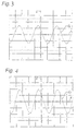
- output signals of the sensor coil (4) are compared by way of example, as they arise on the one hand for the case of a real wheel rotation and on the other hand for an associated wheel rotation simulation.
- the time (t) is plotted on the abscissa and the voltage (U) in arbitrary units on the ordinate on the two oscilloscope screens.
- the image of FIG. 3 shows an induction voltage curve (U R ), as it results in the sensor of FIG. 2 from a real wheel rotation and thus from a rotation of the gear wheel (3).
- U R induction voltage curve
- the sensor-stimulating magnet coil (8) is subjected to an AC voltage frequency when the wheel is stationary, which frequency frequency corresponds to the tooth sequence frequency in the case of the real wheel rotation of FIG. 3. It can be seen that the frequency of the induction voltage (U S ) resulting from this simulation in the measuring coil (4) is identical to that (U R ) of the real wheel rotation, so that the inductive wheel speed sensor system and the vehicle components connected to it by this simulation with respect to their functionality can be checked at any wheel speed or wheel speed curve with vehicle wheels actually standing.
- Wheel rotation simulation device (7) is part of one in the figures 5 and 6 overall test device (11), the majority movable on a running rail (12) in a test section the vehicle production is arranged. Alternatively, you can such a test facility can also be provided in workshops, the test device can also be constructed to be portable.
- the wheel speed-sensitive can be the test device (11) Vehicle components with different functions Check wheel rotation conditions, generally in functional tests without real wheel rotation, i.e. only with simulated wheel rotation, with motor load-free, real wheel rotation and with motor-driven, real wheel rotation can be distinguished.
- the functional tests without engine load and real wheel rotation affect e.g.
- test facility has (11) with a transportable roller unit (14) two rollers (15) per vehicle wheel, alternatively only with a role, which in a manner not shown by a programmable control part of the test device (11) via DC motors can be driven.
- Figure 6 shows the case that the rear wheel drive axle wheels each on a pair of rollers (15) sit on, for which the vehicle (10) with the rear wheels on the ground-based roller units (14) are driven while the front wheels remain in contact with the ground.
- the due the vehicle weight against the rollers (15) with these in rolling connection standing rear wheels are supported by the Rollers (15) for testing the brake system at a relatively low speed driven.
- the current increases when the brake is actuated in the roller-driving DC motors according to the acting braking torque, so that the current measurement Functionality of the brake system can be determined. Analogous can be used to test the front wheels.
- driving dynamics control and electronic transmission control the rear axle drive wheels resting on the rollers (15) optionally driven by the vehicle engine or by the rollers (15) and their speed from the speed sensors without contact inductive sensed or alternatively via an existing diagnostic interface or read out a data bus and as signal information fed to the simulation computer of the test device (11).
- the computer stimulates based on these rear wheel speeds the speed sensors of the stationary front wheels contactless by means of the magnetic coils in the for each Test appropriate way.
- the solenoids for the Front wheels with the mechanical positioning devices (8a, 8b) introduced into the respective sensor magnetic field area, such as this is indicated schematically in Fig. 6. With this configuration can therefore control any driving conditions under computer control, such as traction slip can be simulated.
- the test device described has the advantage that with you relatively complex test processes of wheel speed sensitive Vehicle components with little resources without one conventional, stationary, complex roller test bench Have production and maintenance optimized. Another The advantage of this facility is its high, non-local Flexibility. Appropriate tests can be carried out at the locations be carried out on which the relevant vehicle components be assembled. Installation errors can thus be immediately fix during production. In addition to the explicitly specified are of course other wheel speed dependent Functional tests possible. With the wheel rotation simulation device with sensor-stimulating solenoid all relevant functional tests outside of a conventional, stationary dynamometer. In particular, the external simulative signal feed can the functions of numerous speed-sensitive ones alone Subsystems in the motor vehicle, such as Cruise control, speedometer, Windshield wiper downshift and speed warning buzzer, being checked.
- the remaining function tests e.g. regarding the brake system and an electronic transmission control, can also be used with the compact, portable Roller unit or on a conventional stationary Roller dynamometer are performed, with these tests on Can limit investigations at lower wheel speeds, so that a stationary test bench is no longer at maximum wheel rotation speed needs to be designed. Also reduce the roller dynamometer times and the reduced dimensioning Such test benches enable a considerable reduction in costs.
- test facility described above as part of the Claims specified invention are possible.
- a roller unit firmly anchored in the ground or a roller unit can be provided, in which the Rolling against the wheel of a raised vehicle to ensure the roller-tire-roller contact are pressed.
- a test facility also suitable for vehicles at Hall sensors used for wheel speed monitoring in which a generated and modified wheel speed-dependent Magnetic field a correspondingly varying, measurable electrical Creates tension in a Hall element.
Landscapes
- Physics & Mathematics (AREA)
- General Physics & Mathematics (AREA)
- Regulating Braking Force (AREA)
- Force Measurement Appropriate To Specific Purposes (AREA)
Description
- Fig. 1
- eine schematische Blockdarstellung eines induktiven Raddrehzahlsensors mit zugeordneter Raddrehungs-Simulationsvorrichtung,
- Fig. 2
- eine schematische Blockdarstellung des in Figur 1 gezeigten Raddrehzahlsensors,
- Fig. 3
- ein Oszillograph-Schirmbild mit einem typischen, raddrehzahlrepräsentativen Induktionsspannungssignal des Sensors von Fig.2,
- Fig. 4
- ein Oszillograph-Schirmbild mit einem Sensor-Induktionsspannungssignal, das mit der Anordnung von Fig.1 durch Simulation der zu Fig.3 gehörenden realen Raddrehungen erhalten wird,
- Fig. 5
- eine schematiche Seitenansicht eines Fahrzeugs an einer Prüfeinrichtung mit für alle Räder zu aktivierender Raddrehungs-Simulationsvorrichtung und
- Fig. 6
- eine Ansicht entsprechend Fig.5, jedoch mit nur an den Vorderrädern zu aktivierender Raddrehungs-Simulationsvorrichtung sowie mit einer Rolleneinheit an den Hinterrädern.
Claims (4)
- Prüfeinrichtung für Fahrzeuge mit einem magnetfeldsensitiven Raddrehzahlsensor (1, 2, 3, 4), enthaltend eine Vorrichtung (7) zur Simulation von Raddrehungen mit einer sensorstimulierenden Magnetspule (8), die im Magnetfeldbereich des Sensors (1 bis 4) magnetfeldkoppelnd positionierbar ist, und einer Steuereinheit (9) zur Beaufschlagung der Magnetspule mit einer Wechselspannung, deren Frequenz die sensierte Drehzahl der simulierten Raddrehung bestimmt.
- Prüfeinrichtung nach Anspruch 1, bei der die Steuereinheit aus einem Simulationsrechner (9) besteht, der Wechselspannungssignale, die Raddrehzahlverläufen vorgegebener Fahrzyklen entsprechen, für alle Fahrzeugräder zu erzeugen vermag.
- Prüfeinrichtung nach Anspruch 1 oder 2, mit einer Rolleneinheit (14) mit wenigstens zwei gleichstrommotorbetriebenen Rollen (15), die gegen ein Fahrzeugrad in Rollverbindung mit demselben tretend anlegbar sind.
- Prüfeinrichtung nach Anspruch 3, bei der die Rolleneinheit (14) als transportable Einheit ausgelegt ist, die bodenabgestützt oder frei mit an das Rad anpreßbaren Rollen an einem zugehörigen Fahrzeugrad positionierbar ist.
Applications Claiming Priority (2)
| Application Number | Priority Date | Filing Date | Title |
|---|---|---|---|
| DE4429311 | 1994-08-18 | ||
| DE4429311A DE4429311C2 (de) | 1994-08-18 | 1994-08-18 | Prüfeinrichtung für Fahrzeuge mit magnetfeldsensitivem Raddrehzahlsensor |
Publications (2)
| Publication Number | Publication Date |
|---|---|
| EP0697598A1 EP0697598A1 (de) | 1996-02-21 |
| EP0697598B1 true EP0697598B1 (de) | 1998-09-30 |
Family
ID=6526001
Family Applications (1)
| Application Number | Title | Priority Date | Filing Date |
|---|---|---|---|
| EP95110646A Expired - Lifetime EP0697598B1 (de) | 1994-08-18 | 1995-07-08 | Prüfeinrichtung für Fahrzeuge mit magnetfeldsensitivem Raddrehzahlsensor |
Country Status (5)
| Country | Link |
|---|---|
| US (1) | US5594173A (de) |
| EP (1) | EP0697598B1 (de) |
| JP (1) | JP2729983B2 (de) |
| DE (1) | DE4429311C2 (de) |
| ES (1) | ES2123864T3 (de) |
Families Citing this family (29)
| Publication number | Priority date | Publication date | Assignee | Title |
|---|---|---|---|---|
| DK174370B1 (da) * | 1995-10-30 | 2003-01-13 | Salzkotten Tankanlagen | Flowmåler |
| FR2755514B1 (fr) * | 1996-11-05 | 1998-12-24 | Schneider Electric Sa | Appareil d'aide au reglage d'un detecteur de vitesse de rotation |
| DE19653640A1 (de) * | 1996-12-20 | 1998-06-25 | Teves Gmbh Alfred | Prüfeinrichtung für einen Radsensor |
| FR2778241A1 (fr) * | 1998-04-29 | 1999-11-05 | Arnould Electro Ind | Procede et dispositif de controle de l'etat de fonctionnement d'un capteur inductif |
| DE29815731U1 (de) * | 1998-09-01 | 2000-01-05 | Scheuermann, Harald, 67454 Haßloch | Rollenstand für Kraftfahrzeuge |
| DE10230759A1 (de) * | 2002-07-09 | 2004-01-22 | Zf Friedrichshafen Ag | Verfahren und Einrichtung zur Maschinendiagnose und insbesondere zur Getriebediagnose |
| US20050127685A1 (en) * | 2003-12-03 | 2005-06-16 | Honeywell International Inc. | Latch control by gear position sensing |
| US20060173649A1 (en) * | 2005-01-31 | 2006-08-03 | Shih-Hsiung Wu | Active speed detecting device for vehicle |
| US20080012354A1 (en) * | 2006-05-26 | 2008-01-17 | John Phillip Chevalier | Latch control by gear position sensing |
| DE102007036202B4 (de) * | 2007-11-02 | 2010-03-11 | Knorr-Bremse Systeme für Nutzfahrzeuge GmbH | Prüf- und Simulationsschaltung für Magnetfeldsensoren |
| US8258780B2 (en) * | 2008-09-10 | 2012-09-04 | Smith William L | Self-testing sensor |
| US8203331B2 (en) * | 2009-02-17 | 2012-06-19 | Goodrich Corporation | Non-contact sensor system and method for selection determination |
| US8207729B2 (en) | 2009-02-17 | 2012-06-26 | Goodrich Corporation | Non-contact sensor system and method for displacement determination |
| US8405386B2 (en) * | 2009-02-17 | 2013-03-26 | Goodrich Corporation | Non-contact sensor system and method for position determination |
| US8164326B2 (en) * | 2009-02-17 | 2012-04-24 | Goodrich Corporation | Non-contact sensor system and method for velocity determination |
| DE102009054521A1 (de) * | 2009-07-28 | 2011-02-03 | Continental Teves Ag & Co. Ohg | Drehzahlsensor |
| US8146411B2 (en) * | 2010-03-19 | 2012-04-03 | Lockheed Martin Corporation | Simulating rotation of a wheel |
| GB2489390A (en) * | 2010-09-28 | 2012-10-03 | Synatel Instrumentation Ltd | Sensor arrangement |
| CN104698415B (zh) * | 2013-12-05 | 2019-08-20 | 感知技术无锡有限公司 | 磁敏车辆检测器质量检验方法、装置及系统 |
| CN106771371A (zh) * | 2017-03-20 | 2017-05-31 | 淮海工学院 | 一种汽车轮速传感器检测装置 |
| US10620229B2 (en) | 2017-08-25 | 2020-04-14 | Nxp B.V. | Magnetic field sensor systems and method of determining operability of same |
| US11143732B2 (en) * | 2018-02-21 | 2021-10-12 | Allegro Microsystems, Llc | Magnetic field sensor with modulated diagnostic signal |
| US10677620B2 (en) | 2018-05-01 | 2020-06-09 | Nxp B.V. | System and method for sensor diagnostics during functional operation |
| CN112027109A (zh) * | 2020-09-02 | 2020-12-04 | 中国航空工业集团公司沈阳飞机设计研究所 | 一种轮速仿真装置及其防滑刹车控制测试系统 |
| US12174275B2 (en) | 2021-01-04 | 2024-12-24 | Allegro Microsystems, Llc | Magnetic field closed loop sensors with offset reduction |
| US11927650B2 (en) | 2021-01-04 | 2024-03-12 | Allegro Microsystems, Llc | Magnetic-field closed-loop sensors with diagnostics |
| DE102021001425A1 (de) * | 2021-03-17 | 2022-09-22 | Mercedes-Benz Group AG | Schaltungseinrichtung für ein Getriebe eines Kraftfahrzeugs sowie Verfahren zum Betreiben einer solchen Schaltungseinrichtung |
| CN116413477A (zh) * | 2021-12-29 | 2023-07-11 | 西安航天计量测试研究所 | 一种用于磁电式转速传感器的校准装置及校准方法 |
| US12517195B2 (en) | 2023-12-04 | 2026-01-06 | Allegro Microsystems, Llc | Low residual offset sensor |
Citations (1)
| Publication number | Priority date | Publication date | Assignee | Title |
|---|---|---|---|---|
| GB2096327A (en) * | 1981-04-06 | 1982-10-13 | Weinert E Messgeraetewerk | Testing tachographs |
Family Cites Families (14)
| Publication number | Priority date | Publication date | Assignee | Title |
|---|---|---|---|---|
| US3045227A (en) * | 1958-01-27 | 1962-07-17 | Minas Giorgio | Electromagnetic devices for converting a movement of an electric value |
| US3872720A (en) * | 1974-01-14 | 1975-03-25 | Wagner Electric Corp | Assembly line method for testing anti-skid installations |
| DE2545414C3 (de) * | 1975-10-10 | 1979-02-08 | Lothar 4600 Dortmund Bergmann | Bremsenprüfstand für die Räder von Kraftfahrzeugen |
| US4283031A (en) * | 1977-12-14 | 1981-08-11 | Finch Colin M | System controlling apparatus which compares signals from sensors monitoring passing objects with pre-determined parameter information to control the system |
| DE3034636A1 (de) * | 1980-09-13 | 1982-05-06 | Robert Bosch Gmbh, 7000 Stuttgart | Pruefsystem zur diagnose von kraftfahrzeugen oder fahrzeugbestandteilen |
| GB8609144D0 (en) * | 1986-04-15 | 1986-05-21 | Armstrong Patents Co Ltd | Position sensing |
| JPS62282272A (ja) * | 1986-05-30 | 1987-12-08 | Nissan Motor Co Ltd | 交差コイル式計器の診断回路 |
| EP0308766B1 (de) * | 1987-09-24 | 1991-11-27 | Siemens Aktiengesellschaft | Näherungsschalter mit einer Prüf- und Auswerteschaltung |
| DE3812824A1 (de) * | 1988-04-16 | 1989-11-02 | Asea Brown Boveri | Pruefstand zum testen des antriebsstranges eines fahrzeuges |
| DE4027046A1 (de) * | 1989-09-29 | 1991-04-11 | Siemens Ag | Vorrichtung zum pruefen der funktionsfaehigkeit und/oder eichen eines beschleunigungs-sensors, insbesondere eines aufprall-sensors fuer ein kraftfahrzeug, und verfahren zum betrieb der vorrichtung |
| DE3936988A1 (de) * | 1989-11-07 | 1991-05-08 | Bosch Gmbh Robert | Vorrichtung zur kraftfahrzeugdiagnose |
| US4972145A (en) * | 1989-12-14 | 1990-11-20 | American Standard Inc. | Speed sensor gap fault-detection arrangement for multiple-axle rail vehicles |
| AU3979093A (en) * | 1992-05-06 | 1993-11-29 | Schirnhofer, Leo | Device for testing the operability of a system for detecting heat-radiating particles carried in a particle stream |
| US5375460A (en) * | 1993-04-09 | 1994-12-27 | Clayton Industries | Method and apparatus for testing motor vehicles under simulated road conditions |
-
1994
- 1994-08-18 DE DE4429311A patent/DE4429311C2/de not_active Expired - Fee Related
-
1995
- 1995-07-08 EP EP95110646A patent/EP0697598B1/de not_active Expired - Lifetime
- 1995-07-08 ES ES95110646T patent/ES2123864T3/es not_active Expired - Lifetime
- 1995-08-17 JP JP7242258A patent/JP2729983B2/ja not_active Expired - Lifetime
- 1995-08-18 US US08/516,702 patent/US5594173A/en not_active Expired - Fee Related
Patent Citations (1)
| Publication number | Priority date | Publication date | Assignee | Title |
|---|---|---|---|---|
| GB2096327A (en) * | 1981-04-06 | 1982-10-13 | Weinert E Messgeraetewerk | Testing tachographs |
Also Published As
| Publication number | Publication date |
|---|---|
| EP0697598A1 (de) | 1996-02-21 |
| US5594173A (en) | 1997-01-14 |
| JPH08178804A (ja) | 1996-07-12 |
| ES2123864T3 (es) | 1999-01-16 |
| JP2729983B2 (ja) | 1998-03-18 |
| DE4429311C2 (de) | 1998-05-20 |
| DE4429311A1 (de) | 1996-02-22 |
Similar Documents
| Publication | Publication Date | Title |
|---|---|---|
| EP0697598B1 (de) | Prüfeinrichtung für Fahrzeuge mit magnetfeldsensitivem Raddrehzahlsensor | |
| EP3963303B1 (de) | Verfahren zur überwachung eines riementriebs | |
| DE3627588C2 (de) | Vorrichtung zum Erfassen von Fehlfunktionen eines Sensors | |
| WO1988002491A1 (fr) | Procede et dispositif pour detecter automatiquement la tension de reponse d'un composant electromagnetique, en particulier d'une electrovalve | |
| DE19606826A1 (de) | Verfahren und Vorrichtung zur Überprüfung eines Sensors | |
| DE10328461A1 (de) | Fahrzeugprüfstand | |
| EP2670644B1 (de) | VERFAHREN UND VORRICHTUNG ZUR ÜBERWACHUNG DER BESTIMMUNGSGEMÄßEN FUNKTION MINDESTENS EINER ERSTEN UND EINER ZWEITEN KOMPONENTE EINES FAHRZEUGANTRIEBSSTRANGS | |
| DE102017118566A1 (de) | Erfassungssystem zur Detektion einer Betätigung bei einer Griffvorrichtung eines Fahrzeuges | |
| DE10164108A1 (de) | Verfahren für die Funktionsprüfung eines Querbeschleunigungssensors | |
| EP0881501B1 (de) | Vorrichtung zur Funktionsüberprüfung eines elektronisch gesteuerten Regelsystems in einem Kraftfahrzeug nach einem Fertigungsvorgang | |
| DE102010040644A1 (de) | Prüfstand und Verfahren zum Prüfen einer Bremsanlage eines Kraftfahrzeugs | |
| EP0433668A2 (de) | Rollenprüfstand zur kombinierten Leistungs- und Bremsenprüfung an Kraftfahrzeugen | |
| DE19521411A1 (de) | Verfahren und Anordnung zur Bestimmung der Geschwindigkeit eines Fahrzeuges | |
| EP4137395A1 (de) | Tretwellenanordnung, steuer- und/oder auswerteverfahren und -einheit für eine tretwellenanordnung und fahrzeug | |
| DE4424094C1 (de) | Verfahren und Vorrichtung zur Überprüfung eines Antiblockiersystems in einem Kraftfahrzeug | |
| EP3341695B1 (de) | Verfahren zur kalibrierung eines im antriebsstrang eines kraftfahrzeuges angeordneten drehmomentsensors | |
| DE10143844B4 (de) | Einrichtung zur Überwachung von Kupplungen an Schiffsantrieben | |
| DE10065526B4 (de) | Verfahren und System zum Bestimmen von Motorwerten eines Fahrzeugs | |
| EP1783474B1 (de) | Hydraulischer Schlupfsimulator und Verfahren zum Betreiben eines hydraulischen Schlupfsimulators | |
| DE19825023C2 (de) | Verfahren und Anordnung zum Bestimmen der Motordrehzahl eines Kraftfahrzeugs | |
| DE19544661A1 (de) | Verfahren zur Messung und Aufzeichnung eines Betriebsparameters eines Kraftfahrzeuges | |
| EP0131642A1 (de) | Rollenprüfstand zur Kraftfahrzeugdiagnostik | |
| EP1747427B1 (de) | Verfahren und vorrichtung zur erfassung einer veränderlichen grösse eines fahrzeugs | |
| EP4123277A1 (de) | Drehmomentmessung mit korrektur eines magnetischen fremdfelds | |
| DD287231A5 (de) | Anordnung zum pruefen der funktionsfaehigkeit von antiblockiervorrichtungen |
Legal Events
| Date | Code | Title | Description |
|---|---|---|---|
| PUAI | Public reference made under article 153(3) epc to a published international application that has entered the european phase |
Free format text: ORIGINAL CODE: 0009012 |
|
| AK | Designated contracting states |
Kind code of ref document: A1 Designated state(s): ES FR GB IT SE |
|
| 17P | Request for examination filed |
Effective date: 19960115 |
|
| RAP1 | Party data changed (applicant data changed or rights of an application transferred) |
Owner name: DAIMLER-BENZ AKTIENGESELLSCHAFT |
|
| GRAG | Despatch of communication of intention to grant |
Free format text: ORIGINAL CODE: EPIDOS AGRA |
|
| GRAG | Despatch of communication of intention to grant |
Free format text: ORIGINAL CODE: EPIDOS AGRA |
|
| GRAH | Despatch of communication of intention to grant a patent |
Free format text: ORIGINAL CODE: EPIDOS IGRA |
|
| 17Q | First examination report despatched |
Effective date: 19980212 |
|
| ITF | It: translation for a ep patent filed | ||
| GRAH | Despatch of communication of intention to grant a patent |
Free format text: ORIGINAL CODE: EPIDOS IGRA |
|
| GRAA | (expected) grant |
Free format text: ORIGINAL CODE: 0009210 |
|
| AK | Designated contracting states |
Kind code of ref document: B1 Designated state(s): ES FR GB IT SE |
|
| GBT | Gb: translation of ep patent filed (gb section 77(6)(a)/1977) |
Effective date: 19981014 |
|
| ET | Fr: translation filed | ||
| REG | Reference to a national code |
Ref country code: ES Ref legal event code: FG2A Ref document number: 2123864 Country of ref document: ES Kind code of ref document: T3 |
|
| RAP2 | Party data changed (patent owner data changed or rights of a patent transferred) |
Owner name: DAIMLERCHRYSLER AG |
|
| PLBE | No opposition filed within time limit |
Free format text: ORIGINAL CODE: 0009261 |
|
| STAA | Information on the status of an ep patent application or granted ep patent |
Free format text: STATUS: NO OPPOSITION FILED WITHIN TIME LIMIT |
|
| 26N | No opposition filed | ||
| PGFP | Annual fee paid to national office [announced via postgrant information from national office to epo] |
Ref country code: GB Payment date: 20000614 Year of fee payment: 6 |
|
| PGFP | Annual fee paid to national office [announced via postgrant information from national office to epo] |
Ref country code: SE Payment date: 20000626 Year of fee payment: 6 |
|
| PGFP | Annual fee paid to national office [announced via postgrant information from national office to epo] |
Ref country code: FR Payment date: 20000629 Year of fee payment: 6 |
|
| PGFP | Annual fee paid to national office [announced via postgrant information from national office to epo] |
Ref country code: ES Payment date: 20000720 Year of fee payment: 6 |
|
| REG | Reference to a national code |
Ref country code: GB Ref legal event code: 732E |
|
| PG25 | Lapsed in a contracting state [announced via postgrant information from national office to epo] |
Ref country code: GB Free format text: LAPSE BECAUSE OF NON-PAYMENT OF DUE FEES Effective date: 20010708 |
|
| PG25 | Lapsed in a contracting state [announced via postgrant information from national office to epo] |
Ref country code: SE Free format text: LAPSE BECAUSE OF NON-PAYMENT OF DUE FEES Effective date: 20010709 Ref country code: ES Free format text: LAPSE BECAUSE OF NON-PAYMENT OF DUE FEES Effective date: 20010709 |
|
| GBPC | Gb: european patent ceased through non-payment of renewal fee |
Effective date: 20010708 |
|
| EUG | Se: european patent has lapsed |
Ref document number: 95110646.7 |
|
| PG25 | Lapsed in a contracting state [announced via postgrant information from national office to epo] |
Ref country code: FR Free format text: LAPSE BECAUSE OF NON-PAYMENT OF DUE FEES Effective date: 20020329 |
|
| REG | Reference to a national code |
Ref country code: FR Ref legal event code: ST |
|
| REG | Reference to a national code |
Ref country code: ES Ref legal event code: FD2A Effective date: 20020810 |
|
| PG25 | Lapsed in a contracting state [announced via postgrant information from national office to epo] |
Ref country code: IT Free format text: LAPSE BECAUSE OF NON-PAYMENT OF DUE FEES Effective date: 20050708 |