EP0697585A2 - Dynamomètre électrique - Google Patents
Dynamomètre électrique Download PDFInfo
- Publication number
- EP0697585A2 EP0697585A2 EP95890128A EP95890128A EP0697585A2 EP 0697585 A2 EP0697585 A2 EP 0697585A2 EP 95890128 A EP95890128 A EP 95890128A EP 95890128 A EP95890128 A EP 95890128A EP 0697585 A2 EP0697585 A2 EP 0697585A2
- Authority
- EP
- European Patent Office
- Prior art keywords
- bearing
- ring
- cushion
- bearings
- fixed
- Prior art date
- Legal status (The legal status is an assumption and is not a legal conclusion. Google has not performed a legal analysis and makes no representation as to the accuracy of the status listed.)
- Granted
Links
Images


Classifications
-
- G—PHYSICS
- G01—MEASURING; TESTING
- G01L—MEASURING FORCE, STRESS, TORQUE, WORK, MECHANICAL POWER, MECHANICAL EFFICIENCY, OR FLUID PRESSURE
- G01L3/00—Measuring torque, work, mechanical power, or mechanical efficiency, in general
-
- G—PHYSICS
- G01—MEASURING; TESTING
- G01L—MEASURING FORCE, STRESS, TORQUE, WORK, MECHANICAL POWER, MECHANICAL EFFICIENCY, OR FLUID PRESSURE
- G01L3/00—Measuring torque, work, mechanical power, or mechanical efficiency, in general
- G01L3/16—Rotary-absorption dynamometers, e.g. of brake type
- G01L3/22—Rotary-absorption dynamometers, e.g. of brake type electrically or magnetically actuated
Definitions
- the invention relates to an electric motor brake device for measuring the torque of an engine with a rotor rotating with a shaft and a stator, which is pivotally mounted on its two end faces, each having a disk-shaped bearing plate with a bearing journal, via a bearing in a housing.
- the reaction torque is determined via a lever arm and a load cell.
- the stator of the electric brake is suspended in the housing via roller bearings.
- roller bearings must not have any bearing play to prevent them from knocking in. To achieve this, they are usually axially preloaded. The axial load creates a friction component that shows up as a hysteresis loss when measuring torque. In order to reduce these losses, hydrostatic bearings have already been used for these self-aligning bearings.
- the known designs each consist of two rings, of which the outer is fixed and the inner is designed to be floating. A pin with a lot of play is provided against excessive rotation.
- the gap at the bottom is smaller than at the top.
- the object of the invention is to avoid these disadvantages and to develop a motor brake device of the type mentioned in such a way that the measurement result is influenced as little as possible by the bearing.
- Another object of the invention is to reduce the amount of lubricating oil required.
- the bearings are hydrostatic self-aligning bearings, one of the two self-aligning bearings being designed as an axially movable floating bearing and the other as an axially immovable fixed bearing, and the bearings each consist of a ring pushed onto the bearing journal of the end shield, which is located over two supports rotationally secured bearing bodies, which are arranged on both sides of a longitudinal center plane containing the shaft axis and below a transverse plane normal to the longitudinal center plane and containing the shaft axis, each bearing body consisting of a bearing cushion and a support body fixedly connected to the housing, and the bearing cushion being tiltable on the support body and the ring of the fixed bearing is axially secured against displacement on the bearing cushion.
- the stator is supported in relation to the housing only via the two bearing bodies. Lubrication of the bearing is therefore only necessary in this area.
- the bearing surface between the bearing cushion and the support body is in each case dome-shaped.
- a separate axial stop can be omitted if the outer surface of the ring of the fixed bearing is at least partially toroidal in shape and interacts with a correspondingly shaped contact surface of the bearing cushion.
- the ring of the fixed bearing and the bearing bodies interacting with this ring act self-centering, so that an axial stop is not necessary. If thermal expansion occurs on the internal machine, it can move freely without additional axial forces.
- the axial displacement of the stator relative to the housing is given by the fact that the outer surface of the ring of the floating bearing and the contact surface of the bearing cushion are cylindrical.
- the bearing gaps of the bearing between the ring and the bearing cushion are each connected to a pressure oil connection via channels in the bearing cushion and in the support body and a throttle bore.
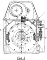
- FIG. 1 and 2 show an electric motor brake device with partial sections
- FIG. 3 shows a front view of a fixed bearing designed according to the invention
- FIG. 4 shows a section through the fixed bearing along the line IV-IV in FIG. 3
- FIG. 5 shows a partial view of a fixed bearing according to the invention 6
- Fig. 7 and 8 two detailed views of a support body of a bearing according to the invention.
- a bearing body is rotated by about 45 ° down
- Fig. 6 a bearing body by about 135 ° up, in the plane of the drawing.
- Fig. 1 shows an electric motor brake device 1 in longitudinal view with partial sections.
- the device 1 consists of a rotor 3 rotating with the shaft 2 and a stator 7 mounted in the housing 6 via the schematically indicated bearings 4 and 5.
- the stator 7 has disk-like end shields 8 and 9 with bearing pins 10 and 11, which were supported on the housing 6 via the bearings 4 and 5.
- the stator is connected to a load cell 13 via a lever arm 12 in order to measure the torque.
- the bearings 4 and 5 are designed as roller bearings.
- the storage according to the invention for the stator 7 provides that the bearings 4 and 5 are designed as hydraulic self-aligning bearings, one self-aligning bearing 4 as a fixed bearing 14 and the other self-aligning bearing 5 as a floating bearing 15.
- a ring 16 is slid over the bearing journal 10 of the end shield 8, which ring has a contact surface 16 ′, which is partially toroidal. Via this, the ring 16 is in contact with correspondingly shaped contact surfaces 17 'of two bearing cushions 17, which are each supported on the housing 6 of the brake device 1 via a support body 18.
- Bearing cushions 17 and support body 18 together form the bearing body 35.
- the support bodies 18 have a spherically shaped surface 20 on which the bearing cushions 17 can adjust themselves in a tiltable manner in all directions.
- a ring 19 is also slid onto a bearing journal 11 of the end shield 9, similarly to the fixed bearing 14.
- this has a cylindrical shape and interacts with cylindrical contact surfaces 22 'of the bearing pads 22 designed as cylinders.
- the bearing cushions 22 are again supported on dome surfaces 23 on support bodies 24 which are fixedly connected to the housing 6 and can be set automatically in all directions by tilting. When thermal expansions of the inner machine 37 consisting of rotor 3 and stator 7 relative to the housing 6 occur, the latter can move freely without additional axial forces.
- a plane 35 'or 36' spanned by the shaft axis 2 'and the bearing bodies 35 or 36 has an angle ⁇ of approximately 45 ° with respect to the longitudinal center plane 38.
- the support bodies 18 and 24 are each clamped onto the housing 6 via screw connections 25.
- the screw connections 25 can also be designed as an oil connection 26.
- the pressure oil is supplied via an oil connection 26 from a pressure oil system, not shown, via the pipes 27 and passes through a throttle 28 and oil channels 29 and 30 in the support bodies 18, 24 and the bearing pads 17, 22 to the bearing gaps 31, 32. That from Oil emerging from the bearing gaps 31, 32 is collected in the housing 6 at the lowest point and via an oil outlet 33, 34 in each case and a pipeline 33 ', 34' is sucked out of the fixed bearing 14 and the floating bearing 15.
- the throttle 28 in each screw connection 25 ensures that all four bearing gaps 31, 32 are evenly supplied with oil.
- the contact surfaces 16 ', 19', 17 ', 22' between the rings 16 and 19 and the bearing pads 17 and 22 form the actual hydrostatic bearing. Due to the load and the oil flow through the bearing gaps 31 and 32, a certain oil pressure is set in the bearing pads 17 and 22, respectively. Depending on the load, the bearing gap 31 or 32 becomes larger or smaller and the pressure conversely becomes smaller or larger.
- the bearing gap 31 or 32 on the ring 16 or 19 can always set itself automatically.
Landscapes
- Physics & Mathematics (AREA)
- General Physics & Mathematics (AREA)
- Connection Of Motors, Electrical Generators, Mechanical Devices, And The Like (AREA)
- Magnetic Bearings And Hydrostatic Bearings (AREA)
- Support Of The Bearing (AREA)
- Motor Or Generator Frames (AREA)
- Braking Arrangements (AREA)
Applications Claiming Priority (3)
| Application Number | Priority Date | Filing Date | Title |
|---|---|---|---|
| AT0025094U AT350U1 (de) | 1994-08-18 | 1994-08-18 | Elektrische motorbremsvorrichtung |
| AT25094 | 1994-08-18 | ||
| AT250/94 | 1994-08-18 |
Publications (3)
| Publication Number | Publication Date |
|---|---|
| EP0697585A2 true EP0697585A2 (fr) | 1996-02-21 |
| EP0697585A3 EP0697585A3 (fr) | 1997-02-12 |
| EP0697585B1 EP0697585B1 (fr) | 1999-09-22 |
Family
ID=3485549
Family Applications (1)
| Application Number | Title | Priority Date | Filing Date |
|---|---|---|---|
| EP95890128A Expired - Lifetime EP0697585B1 (fr) | 1994-08-18 | 1995-07-03 | Dynamomètre électrique |
Country Status (5)
| Country | Link |
|---|---|
| US (1) | US5575359A (fr) |
| EP (1) | EP0697585B1 (fr) |
| KR (1) | KR100189582B1 (fr) |
| AT (2) | AT350U1 (fr) |
| DE (1) | DE59506877D1 (fr) |
Cited By (1)
| Publication number | Priority date | Publication date | Assignee | Title |
|---|---|---|---|---|
| EP1039282B2 (fr) † | 1999-01-11 | 2010-12-22 | MAHA-AIP GmbH & Co. KG | Banc d'essai à rouleaux pour véhicules |
Families Citing this family (1)
| Publication number | Priority date | Publication date | Assignee | Title |
|---|---|---|---|---|
| US6505503B1 (en) | 1998-12-21 | 2003-01-14 | Teresi Publications, Inc. | Stationary drag racing simulation system |
Family Cites Families (13)
| Publication number | Priority date | Publication date | Assignee | Title |
|---|---|---|---|---|
| DE2059684A1 (de) * | 1970-12-04 | 1972-06-08 | Arndt Franz Martin | Hydrostatisches Axialeinstell-Lager |
| US3789659A (en) * | 1971-11-02 | 1974-02-05 | Megatech Corp | Electromechanical dynamometer system |
| US3978718A (en) * | 1973-07-30 | 1976-09-07 | Schorsch Ronald W | Electronic dynamometer |
| DE2444035A1 (de) * | 1974-09-14 | 1976-03-25 | Volkswagenwerk Ag | Drehmoment-messgeraet |
| JPS52155002U (fr) * | 1976-05-20 | 1977-11-25 | ||
| DE2654863C2 (de) * | 1976-12-03 | 1978-12-14 | Motoren- Und Turbinen-Union Muenchen Gmbh, 8000 Muenchen | Drehmomentenmeßvorrichtung für Gasturbinentriebwerke, insbesondere Gasturbinenstrahltriebwerke |
| US4457182A (en) * | 1982-05-17 | 1984-07-03 | Mcfarland Robert A | Throttle controller for engines in dynamometer testing |
| US4478090A (en) * | 1982-05-17 | 1984-10-23 | Mcfarland Robert A | Dynamometer controllers |
| JP2623758B2 (ja) * | 1988-09-05 | 1997-06-25 | 株式会社明電舎 | ディーゼルエンジンのトルク制御装置 |
| DE4029361C1 (en) * | 1990-09-15 | 1991-09-19 | Anton Piller Gmbh & Co Kg, 3360 Osterode, De | Bearing unit for shaft of pendulum machine measuring torque - is rigid in radial direction but deformable in tangential direction |
| CA2067706A1 (fr) * | 1992-03-12 | 1993-09-13 | John E. Duncan | Frein a hysteresis et methode d'etalonnage connexe |
| US5469741A (en) * | 1993-06-18 | 1995-11-28 | Lucas Automation & Control Engineering, Inc. | Apparatus and methods for detecting imbalance |
| FR2714546B1 (fr) * | 1993-12-23 | 1996-03-01 | Labavia | Ralentisseur à courants de Foucault à estimation de couple. |
-
1994
- 1994-08-18 AT AT0025094U patent/AT350U1/de not_active IP Right Cessation
-
1995
- 1995-07-03 DE DE59506877T patent/DE59506877D1/de not_active Expired - Lifetime
- 1995-07-03 EP EP95890128A patent/EP0697585B1/fr not_active Expired - Lifetime
- 1995-07-03 AT AT95890128T patent/ATE184987T1/de active
- 1995-08-10 US US08/513,515 patent/US5575359A/en not_active Expired - Lifetime
- 1995-08-18 KR KR1019950025444A patent/KR100189582B1/ko not_active Expired - Fee Related
Non-Patent Citations (1)
| Title |
|---|
| None |
Cited By (1)
| Publication number | Priority date | Publication date | Assignee | Title |
|---|---|---|---|---|
| EP1039282B2 (fr) † | 1999-01-11 | 2010-12-22 | MAHA-AIP GmbH & Co. KG | Banc d'essai à rouleaux pour véhicules |
Also Published As
| Publication number | Publication date |
|---|---|
| AT350U1 (de) | 1995-08-25 |
| ATE184987T1 (de) | 1999-10-15 |
| US5575359A (en) | 1996-11-19 |
| EP0697585B1 (fr) | 1999-09-22 |
| KR100189582B1 (ko) | 1999-06-01 |
| DE59506877D1 (de) | 1999-10-28 |
| EP0697585A3 (fr) | 1997-02-12 |
| KR960008283A (ko) | 1996-03-22 |
Similar Documents
| Publication | Publication Date | Title |
|---|---|---|
| DE2703535C2 (de) | Wälzmühle | |
| EP2049016B1 (fr) | Dispositif pourvu d'un corps de rotation a entrainement direct et d'un palier aerostatique | |
| DE2725572C2 (de) | Hydrodynamisches Gleitlager | |
| DE2709102A1 (de) | Tandem-schublageranordnung | |
| DE112013006848T5 (de) | Lagerstruktur einer rotierenden Welle | |
| DE3886190T2 (de) | Axiallager. | |
| CH650065A5 (de) | Spielfreier praezisionsantrieb, der ein drehbares teil oder ein laengsverschiebliches teil antreibt. | |
| CH674060A5 (fr) | ||
| DE69326942T2 (de) | Spiralverdichter | |
| CH644191A5 (de) | Vorrichtung zur lagerung eines rotors. | |
| DE60105374T2 (de) | Gleitlager für Papiermaschinen | |
| EP0697585A2 (fr) | Dynamomètre électrique | |
| DE2741281B2 (de) | Gasdichtung für rotierendes Mahlwerk mit Umfangs-Ausgabe | |
| DE2948013A1 (de) | Kombiniertes kamm- traglager fuer turbogeneratoren | |
| DE2801363C2 (fr) | ||
| DE3531720A1 (de) | Hydrodynamisches fluidfilmlager | |
| CH657901A5 (de) | Axialgleitlager-vorrichtung an einer vertikal angeordneten welle. | |
| DE2615471C2 (de) | Hydrostatischer Gleitschuh | |
| DE102007018796B4 (de) | Ausgleich umlaufender Wellenschrägstellung | |
| EP1717466A2 (fr) | Palier lisse avec un entrefer divergeant dans la zone d'extrémité | |
| DE4316579A1 (de) | Lagerung für Drehtrommeln wie z. B. Rohrmühlen | |
| DE3902907A1 (de) | Vorrichtung zur lagerung von wellen langgestreckter maschinen | |
| EP0031415B1 (fr) | Dispositif d'étanchéité d'arbre pour rouleaux distributeurs d'encrage pour machines à imprimer | |
| DE3125639C2 (de) | "Verstelleinrichtung für die Leitschaufeln einer Axialturbomaschine" | |
| CH616608A5 (en) | Strand guiding track for a continuous casting installation |
Legal Events
| Date | Code | Title | Description |
|---|---|---|---|
| PUAI | Public reference made under article 153(3) epc to a published international application that has entered the european phase |
Free format text: ORIGINAL CODE: 0009012 |
|
| AK | Designated contracting states |
Kind code of ref document: A2 Designated state(s): AT DE FR IT |
|
| PUAL | Search report despatched |
Free format text: ORIGINAL CODE: 0009013 |
|
| AK | Designated contracting states |
Kind code of ref document: A3 Designated state(s): AT DE FR IT |
|
| RAP1 | Party data changed (applicant data changed or rights of an application transferred) |
Owner name: AVL LIST GMBH |
|
| 17P | Request for examination filed |
Effective date: 19970416 |
|
| GRAG | Despatch of communication of intention to grant |
Free format text: ORIGINAL CODE: EPIDOS AGRA |
|
| GRAG | Despatch of communication of intention to grant |
Free format text: ORIGINAL CODE: EPIDOS AGRA |
|
| GRAH | Despatch of communication of intention to grant a patent |
Free format text: ORIGINAL CODE: EPIDOS IGRA |
|
| 17Q | First examination report despatched |
Effective date: 19990122 |
|
| GRAH | Despatch of communication of intention to grant a patent |
Free format text: ORIGINAL CODE: EPIDOS IGRA |
|
| GRAA | (expected) grant |
Free format text: ORIGINAL CODE: 0009210 |
|
| AK | Designated contracting states |
Kind code of ref document: B1 Designated state(s): AT DE FR IT |
|
| REF | Corresponds to: |
Ref document number: 184987 Country of ref document: AT Date of ref document: 19991015 Kind code of ref document: T |
|
| REF | Corresponds to: |
Ref document number: 59506877 Country of ref document: DE Date of ref document: 19991028 |
|
| ET | Fr: translation filed | ||
| ITF | It: translation for a ep patent filed | ||
| PLBE | No opposition filed within time limit |
Free format text: ORIGINAL CODE: 0009261 |
|
| STAA | Information on the status of an ep patent application or granted ep patent |
Free format text: STATUS: NO OPPOSITION FILED WITHIN TIME LIMIT |
|
| 26N | No opposition filed | ||
| PGFP | Annual fee paid to national office [announced via postgrant information from national office to epo] |
Ref country code: AT Payment date: 20130731 Year of fee payment: 19 Ref country code: DE Payment date: 20130726 Year of fee payment: 19 |
|
| PGFP | Annual fee paid to national office [announced via postgrant information from national office to epo] |
Ref country code: FR Payment date: 20130730 Year of fee payment: 19 |
|
| PGFP | Annual fee paid to national office [announced via postgrant information from national office to epo] |
Ref country code: IT Payment date: 20130729 Year of fee payment: 19 |
|
| REG | Reference to a national code |
Ref country code: DE Ref legal event code: R119 Ref document number: 59506877 Country of ref document: DE |
|
| REG | Reference to a national code |
Ref country code: AT Ref legal event code: MM01 Ref document number: 184987 Country of ref document: AT Kind code of ref document: T Effective date: 20140703 |
|
| REG | Reference to a national code |
Ref country code: FR Ref legal event code: ST Effective date: 20150331 |
|
| PG25 | Lapsed in a contracting state [announced via postgrant information from national office to epo] |
Ref country code: DE Free format text: LAPSE BECAUSE OF NON-PAYMENT OF DUE FEES Effective date: 20150203 Ref country code: IT Free format text: LAPSE BECAUSE OF NON-PAYMENT OF DUE FEES Effective date: 20140703 |
|
| REG | Reference to a national code |
Ref country code: DE Ref legal event code: R119 Ref document number: 59506877 Country of ref document: DE Effective date: 20150203 |
|
| PG25 | Lapsed in a contracting state [announced via postgrant information from national office to epo] |
Ref country code: AT Free format text: LAPSE BECAUSE OF NON-PAYMENT OF DUE FEES Effective date: 20140703 Ref country code: FR Free format text: LAPSE BECAUSE OF NON-PAYMENT OF DUE FEES Effective date: 20140731 |