EP0697585A2 - Electric dynamo meter - Google Patents
Electric dynamo meter Download PDFInfo
- Publication number
- EP0697585A2 EP0697585A2 EP95890128A EP95890128A EP0697585A2 EP 0697585 A2 EP0697585 A2 EP 0697585A2 EP 95890128 A EP95890128 A EP 95890128A EP 95890128 A EP95890128 A EP 95890128A EP 0697585 A2 EP0697585 A2 EP 0697585A2
- Authority
- EP
- European Patent Office
- Prior art keywords
- bearing
- ring
- cushion
- bearings
- fixed
- Prior art date
- Legal status (The legal status is an assumption and is not a legal conclusion. Google has not performed a legal analysis and makes no representation as to the accuracy of the status listed.)
- Granted
Links
- 230000002706 hydrostatic effect Effects 0.000 claims abstract description 5
- 238000006073 displacement reaction Methods 0.000 claims description 3
- 239000003921 oil Substances 0.000 description 14
- 238000005259 measurement Methods 0.000 description 3
- 239000010687 lubricating oil Substances 0.000 description 2
- 238000006243 chemical reaction Methods 0.000 description 1
- 238000005461 lubrication Methods 0.000 description 1
Images


Classifications
-
- G—PHYSICS
- G01—MEASURING; TESTING
- G01L—MEASURING FORCE, STRESS, TORQUE, WORK, MECHANICAL POWER, MECHANICAL EFFICIENCY, OR FLUID PRESSURE
- G01L3/00—Measuring torque, work, mechanical power, or mechanical efficiency, in general
-
- G—PHYSICS
- G01—MEASURING; TESTING
- G01L—MEASURING FORCE, STRESS, TORQUE, WORK, MECHANICAL POWER, MECHANICAL EFFICIENCY, OR FLUID PRESSURE
- G01L3/00—Measuring torque, work, mechanical power, or mechanical efficiency, in general
- G01L3/16—Rotary-absorption dynamometers, e.g. of brake type
- G01L3/22—Rotary-absorption dynamometers, e.g. of brake type electrically or magnetically actuated
Definitions
- the invention relates to an electric motor brake device for measuring the torque of an engine with a rotor rotating with a shaft and a stator, which is pivotally mounted on its two end faces, each having a disk-shaped bearing plate with a bearing journal, via a bearing in a housing.
- the reaction torque is determined via a lever arm and a load cell.
- the stator of the electric brake is suspended in the housing via roller bearings.
- roller bearings must not have any bearing play to prevent them from knocking in. To achieve this, they are usually axially preloaded. The axial load creates a friction component that shows up as a hysteresis loss when measuring torque. In order to reduce these losses, hydrostatic bearings have already been used for these self-aligning bearings.
- the known designs each consist of two rings, of which the outer is fixed and the inner is designed to be floating. A pin with a lot of play is provided against excessive rotation.
- the gap at the bottom is smaller than at the top.
- the object of the invention is to avoid these disadvantages and to develop a motor brake device of the type mentioned in such a way that the measurement result is influenced as little as possible by the bearing.
- Another object of the invention is to reduce the amount of lubricating oil required.
- the bearings are hydrostatic self-aligning bearings, one of the two self-aligning bearings being designed as an axially movable floating bearing and the other as an axially immovable fixed bearing, and the bearings each consist of a ring pushed onto the bearing journal of the end shield, which is located over two supports rotationally secured bearing bodies, which are arranged on both sides of a longitudinal center plane containing the shaft axis and below a transverse plane normal to the longitudinal center plane and containing the shaft axis, each bearing body consisting of a bearing cushion and a support body fixedly connected to the housing, and the bearing cushion being tiltable on the support body and the ring of the fixed bearing is axially secured against displacement on the bearing cushion.
- the stator is supported in relation to the housing only via the two bearing bodies. Lubrication of the bearing is therefore only necessary in this area.
- the bearing surface between the bearing cushion and the support body is in each case dome-shaped.
- a separate axial stop can be omitted if the outer surface of the ring of the fixed bearing is at least partially toroidal in shape and interacts with a correspondingly shaped contact surface of the bearing cushion.
- the ring of the fixed bearing and the bearing bodies interacting with this ring act self-centering, so that an axial stop is not necessary. If thermal expansion occurs on the internal machine, it can move freely without additional axial forces.
- the axial displacement of the stator relative to the housing is given by the fact that the outer surface of the ring of the floating bearing and the contact surface of the bearing cushion are cylindrical.
- the bearing gaps of the bearing between the ring and the bearing cushion are each connected to a pressure oil connection via channels in the bearing cushion and in the support body and a throttle bore.
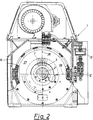
- FIG. 1 and 2 show an electric motor brake device with partial sections
- FIG. 3 shows a front view of a fixed bearing designed according to the invention
- FIG. 4 shows a section through the fixed bearing along the line IV-IV in FIG. 3
- FIG. 5 shows a partial view of a fixed bearing according to the invention 6
- Fig. 7 and 8 two detailed views of a support body of a bearing according to the invention.
- a bearing body is rotated by about 45 ° down
- Fig. 6 a bearing body by about 135 ° up, in the plane of the drawing.
- Fig. 1 shows an electric motor brake device 1 in longitudinal view with partial sections.
- the device 1 consists of a rotor 3 rotating with the shaft 2 and a stator 7 mounted in the housing 6 via the schematically indicated bearings 4 and 5.
- the stator 7 has disk-like end shields 8 and 9 with bearing pins 10 and 11, which were supported on the housing 6 via the bearings 4 and 5.
- the stator is connected to a load cell 13 via a lever arm 12 in order to measure the torque.
- the bearings 4 and 5 are designed as roller bearings.
- the storage according to the invention for the stator 7 provides that the bearings 4 and 5 are designed as hydraulic self-aligning bearings, one self-aligning bearing 4 as a fixed bearing 14 and the other self-aligning bearing 5 as a floating bearing 15.
- a ring 16 is slid over the bearing journal 10 of the end shield 8, which ring has a contact surface 16 ′, which is partially toroidal. Via this, the ring 16 is in contact with correspondingly shaped contact surfaces 17 'of two bearing cushions 17, which are each supported on the housing 6 of the brake device 1 via a support body 18.
- Bearing cushions 17 and support body 18 together form the bearing body 35.
- the support bodies 18 have a spherically shaped surface 20 on which the bearing cushions 17 can adjust themselves in a tiltable manner in all directions.
- a ring 19 is also slid onto a bearing journal 11 of the end shield 9, similarly to the fixed bearing 14.
- this has a cylindrical shape and interacts with cylindrical contact surfaces 22 'of the bearing pads 22 designed as cylinders.
- the bearing cushions 22 are again supported on dome surfaces 23 on support bodies 24 which are fixedly connected to the housing 6 and can be set automatically in all directions by tilting. When thermal expansions of the inner machine 37 consisting of rotor 3 and stator 7 relative to the housing 6 occur, the latter can move freely without additional axial forces.
- a plane 35 'or 36' spanned by the shaft axis 2 'and the bearing bodies 35 or 36 has an angle ⁇ of approximately 45 ° with respect to the longitudinal center plane 38.
- the support bodies 18 and 24 are each clamped onto the housing 6 via screw connections 25.
- the screw connections 25 can also be designed as an oil connection 26.
- the pressure oil is supplied via an oil connection 26 from a pressure oil system, not shown, via the pipes 27 and passes through a throttle 28 and oil channels 29 and 30 in the support bodies 18, 24 and the bearing pads 17, 22 to the bearing gaps 31, 32. That from Oil emerging from the bearing gaps 31, 32 is collected in the housing 6 at the lowest point and via an oil outlet 33, 34 in each case and a pipeline 33 ', 34' is sucked out of the fixed bearing 14 and the floating bearing 15.
- the throttle 28 in each screw connection 25 ensures that all four bearing gaps 31, 32 are evenly supplied with oil.
- the contact surfaces 16 ', 19', 17 ', 22' between the rings 16 and 19 and the bearing pads 17 and 22 form the actual hydrostatic bearing. Due to the load and the oil flow through the bearing gaps 31 and 32, a certain oil pressure is set in the bearing pads 17 and 22, respectively. Depending on the load, the bearing gap 31 or 32 becomes larger or smaller and the pressure conversely becomes smaller or larger.
- the bearing gap 31 or 32 on the ring 16 or 19 can always set itself automatically.
Landscapes
- Physics & Mathematics (AREA)
- General Physics & Mathematics (AREA)
- Connection Of Motors, Electrical Generators, Mechanical Devices, And The Like (AREA)
- Braking Arrangements (AREA)
- Magnetic Bearings And Hydrostatic Bearings (AREA)
- Support Of The Bearing (AREA)
- Motor Or Generator Frames (AREA)
Abstract
Description
Die Erfindung betrifft eine elektrische Motorbremsvorrichtung zur Messung des Drehmomentes einer Kraftmaschine mit einem mit einer Welle umlaufenden Rotor und einem Stator, welcher an seinen beiden jeweils einen scheibenförmigen Lagerschild mit einem Lagerzapfen aufweisenden Stirnseiten jeweils über ein Lager in einem Gehäuse pendelnd gelagert ist.The invention relates to an electric motor brake device for measuring the torque of an engine with a rotor rotating with a shaft and a stator, which is pivotally mounted on its two end faces, each having a disk-shaped bearing plate with a bearing journal, via a bearing in a housing.
Um das Drehmoment einer Kraftmaschine mit einer elektrischen Motorbremsvorrichtung zu messen, wird das Reaktionsmoment über einen Hebelarm und eine Kraftmeßdose festgestellt. Bei bekannten elektrischen Motorbremsvorrichtungen ist der Stator der elektrischen Bremse pendelnd im Gehäuse über Wälzlager aufgehängt.In order to measure the torque of an engine with an electric motor brake device, the reaction torque is determined via a lever arm and a load cell. In known electric motor brake devices, the stator of the electric brake is suspended in the housing via roller bearings.
Diese Wälzlager dürfen, um ein Einschlagen zu verhindern, kein Lagerspiel aufweisen. Um das zu erreichen, werden sie üblicherweise axial vorgespannt. Durch die Axiallast entsteht ein Reibungsanteil, der sich als Hysteresisverlust beim Drehmomentmessen zeigt. Um diese Verluste zu verringen, wurden hydrostatische Lager für diese Pendellager bereits eingesetzt.These roller bearings must not have any bearing play to prevent them from knocking in. To achieve this, they are usually axially preloaded. The axial load creates a friction component that shows up as a hysteresis loss when measuring torque. In order to reduce these losses, hydrostatic bearings have already been used for these self-aligning bearings.
Die bekannten Ausführungen bestehen aus jeweils zwei Ringen, von denen der äußere festeht und der innere schwimmend ausgeführt ist. Gegen zu große Verdrehung ist ein Stift mit viel Spiel vorgesehen.The known designs each consist of two rings, of which the outer is fixed and the inner is designed to be floating. A pin with a lot of play is provided against excessive rotation.
Axiale Kräfte werden durch Anlaufen des schwimmenden Ringes an die Gehäuseteile aufgenommen. Dabei entsteht wieder Reibung, die auf die Messung Einfluß nehmen kann.Axial forces are absorbed by the floating ring against the housing parts. This creates friction again, which can influence the measurement.
Weiters ist bei dieser Lagerung durch das große Gewicht der Innenmaschine (Rotor und Stator) oder der gesamten Bremse (Rotor, Stator und Gehäuse) der Spalt unten kleiner als oben.Furthermore, due to the heavy weight of the internal machine (rotor and stator) or the entire brake (rotor, stator and housing), the gap at the bottom is smaller than at the top.
Aus dem oberen Bereich jedes Lagers fließt daher mehr Öl ab als aus dem unteren Bereich, was die erforderliche Ölmenge überflüssigerweise vergrößert.Therefore, more oil flows out of the upper area of each bearing than from the lower area, which unnecessarily increases the amount of oil required.
Bei anderen bekannten Ausführungen von Motorbremsvorrichtungen sind hydraulische Kissen vorgesehen, die keinerlei axiale Kräfte aufnehmen können. Bei diesen werden die Axialkräfte einfach über einen prismatischen Körper, der in ein Ölbad taucht, am Gehäuse abgestützt. Hier wird ebenfalls das Meßergebnis durch den Reibungseinfluß verfälscht.In other known designs of engine braking devices, hydraulic pads are provided that cannot absorb any axial forces. With these, the axial forces are simply applied via a prismatic body that is placed in an oil bath dives, supported on the housing. Here, too, the measurement result is falsified by the influence of friction.
Aufgabe der Erfindung ist es, diese Nachteile zu vermeiden und eine Motorbremsvorrichtung der eingangs genannten Art derart weiterzubilden, daß das Meßergebnis von der Lagerung möglichst wenig beeinflußt wird.The object of the invention is to avoid these disadvantages and to develop a motor brake device of the type mentioned in such a way that the measurement result is influenced as little as possible by the bearing.
Eine weitere Aufgabe der Erfindung ist es, die erforderliche Schmierölmenge zu verkleinern.Another object of the invention is to reduce the amount of lubricating oil required.
Erfindungsgemäß wird dies dadurch erreicht, daß die Lager hydrostatische Pendellager sind, wobei eines der beiden Pendellager als axial bewegliches Loslager und das andere als axial unbewegliches Festlager ausgeführt ist, und die Lager jeweils aus einem am Lagerzapfen des Lagerschildes aufgeschobenen Ring bestehen, welcher sich über zwei drehgesicherte Lagerkörper abstützt, die beidseitig einer die Wellenachse beinhaltenden Längsmittelebene und unterhalb einer zur Längsmittelebene normal stehenden, die Wellenachse beinhaltenden Querebene angeordnet sind, wobei jeder Lagerkörper aus einem Lagerkissen und einem mit dem Gehäuse fest verbundenen Stützkörper besteht, und wobei jeweils das Lagerkissen am Stützkörper kippbar und der Ring des Festlagers am Lagerkissen axial verschiebegesichert gelagert ist. Die Abstützung des Stators gegenüber dem Gehäuse erfolgt dabei lediglich über die zwei Lagerkörper. Eine Schmierung des Lagers ist daher nur in diesem Bereich erforderlich.According to the invention this is achieved in that the bearings are hydrostatic self-aligning bearings, one of the two self-aligning bearings being designed as an axially movable floating bearing and the other as an axially immovable fixed bearing, and the bearings each consist of a ring pushed onto the bearing journal of the end shield, which is located over two supports rotationally secured bearing bodies, which are arranged on both sides of a longitudinal center plane containing the shaft axis and below a transverse plane normal to the longitudinal center plane and containing the shaft axis, each bearing body consisting of a bearing cushion and a support body fixedly connected to the housing, and the bearing cushion being tiltable on the support body and the ring of the fixed bearing is axially secured against displacement on the bearing cushion. The stator is supported in relation to the housing only via the two bearing bodies. Lubrication of the bearing is therefore only necessary in this area.
Vorzugsweise ist vorgesehen, daß die Lagerfläche zwischen Lagerkissen und Stützkörper jeweils kalottenförmig ausgebildet ist. Durch die damit erzielte kippbare Lagerung der Lagerkissen auf den Stützkörpern kann sich der Lagerspalt zwischen Ring und Lagerkörper selbsttätig gleichmäßig einstellen.It is preferably provided that the bearing surface between the bearing cushion and the support body is in each case dome-shaped. As a result of the tiltable mounting of the bearing cushions on the support bodies, the bearing gap between the ring and the bearing body can adjust itself automatically.
Ein eigener axialer Anschlag kann entfallen, wenn die Außenfläche des Ringes des Festlagers zumindest teilweise torusartige Gestalt aufweist und mit einer entsprechend geformten Kontaktfläche des Lagerkissens zusammenwirkt. Der Ring des Festlagers und die mit diesem Ring zusammenwirkenden Lagerkörper wirken selbstzentrierend, sodaß ein axialer Anschlag nicht erforderlich ist. Beim Auftreten von Wärmedehnungen der Innenmaschine kann sich diese frei ohne axiale Zusatzkräfte bewegen.A separate axial stop can be omitted if the outer surface of the ring of the fixed bearing is at least partially toroidal in shape and interacts with a correspondingly shaped contact surface of the bearing cushion. The ring of the fixed bearing and the bearing bodies interacting with this ring act self-centering, so that an axial stop is not necessary. If thermal expansion occurs on the internal machine, it can move freely without additional axial forces.
Die axiale Verschiebbarkeit des Stators gegenüber dem Gehäuse ist dadurch gegeben, daß die Außenfläche des Ringes des Loslagers sowie die Kontaktfläche des Lagerkissens zylindrisch geformt sind.The axial displacement of the stator relative to the housing is given by the fact that the outer surface of the ring of the floating bearing and the contact surface of the bearing cushion are cylindrical.
In Weiterbildung der Erfindung ist vorgesehen, daß die Lagerspalte des Lagers zwischen Ring und Lagerkissen jeweils über Kanäle im Lagerkissen und in Stützkörper und einer Drosselbohrung mit einem Druckölanschluß verbunden sind. Das Schmieröl kann dadurch fein dosiert nur in der erforderlichen Menge den eigentlichen Lagerbereichen zugeführt werden.In a further development of the invention it is provided that the bearing gaps of the bearing between the ring and the bearing cushion are each connected to a pressure oil connection via channels in the bearing cushion and in the support body and a throttle bore. As a result, the lubricating oil can only be fed into the actual storage areas in the required amount.
Die Erfindung wird anhand der Figuren näher erläutert. Es zeigen Fig. 1 und 2 eine elektrische Motorbremsvorrichtung mit Teilschnitten, Fig. 3 eine Vorderansicht auf ein erfindungsgemäß ausgebildetes Festlager, Fig. 4 einen Schnitt durch das Festlager nach der Linie IV-IV in Fig 3, Fig. 5 eine Teilansicht auf ein erfindungsgemäß ausgebildetes Loslager, Fig. 6 ein Loslager im Schnitt nach der Linie VI-VI in Fig. 5, Fig. 7 und 8 zwei Detailansichten eines Stützkörpers eines erfindungsgemäßen Lagers. In Fig. 4 ist ein Lagerkörper um etwa 45° nach unten, in Fig. 6 ein Lagerkörper um etwa 135° nach oben, in die Zeichenebene gedreht.The invention is explained in more detail with reference to the figures. 1 and 2 show an electric motor brake device with partial sections, FIG. 3 shows a front view of a fixed bearing designed according to the invention, FIG. 4 shows a section through the fixed bearing along the line IV-IV in FIG. 3, FIG. 5 shows a partial view of a fixed bearing according to the
Fig. 1 zeigt eine elektrische Motorbremsvorrichtung 1 in Längsansicht mit Teilschnitten. Die Vorrichtung 1 besteht aus einem mit der Welle 2 umlaufendem Rotor 3 sowie einem über die schematisch angedeuteten Lager 4 und 5 im Gehäuse 6 gelagerten Stator 7. Im Bereich der Stirnseiten weist der Stator 7 scheibenartige Lagerschilde 8 und 9 mit Lagerzapfen 10 und 11 auf, welche sich über die Lager 4 und 5 am Gehäuse 6 abstützten.Fig. 1 shows an electric
Wie in Fig. 2 ersichtlich ist, ist der Stator über einen Hebelarm 12 mit einer Kraftmeßdose 13 verbunden, um das Drehmoment zu messen.As can be seen in FIG. 2, the stator is connected to a
Bei konventionellen Vorrichtungen sind die Lager 4 und 5 als Wälzlager ausgebildet.In conventional devices, the
Die erfindungsgemäße Lagerung für den Stator 7 sieht vor, daß die Lager 4 und 5 als hydraulische Pendellager ausgeführt sind, wobei das eine Pendellager 4 als Festlager 14 und das andere Pendellager 5 als Loslager 15 ausgeführt ist.The storage according to the invention for the
Wie in den Fig. 3 und 4 gezeigt ist, ist beim Festlager 14 über den Lagerzapfen 10 des Lagerschildes 8 ein Ring 16 aufgeschoben, welcher eine zum Teil torusartig gestaltete Kontaktfläche 16' aufweist. Über diese steht der Ring 16 in Kontakt mit entsprechend geformten Kontaktflächen 17' zweier Lagerkissen 17, welche über jeweils einen Stützkörper 18 am Gehäuse 6 der Bremsvorrichtung 1 abgestützt sind. Lagerkissen 17 und Stützkörper 18 bilden zusammen den Lagerkörper 35. Die Stützkörper 18 weisen eine kalottenförmig gestaltete Fläche 20 auf, auf der sich die Lagerkissen 17 kippbar in allen Richtungen selbsttätig einstellen können.As shown in FIGS. 3 and 4, in the fixed bearing 14, a
Beim in Fig. 5 und 6 dargestellten Loslager 15 ist analog zum Festlager 14 ebenfalls ein Ring 19 auf einen Lagerzapfen 11 des Lagerschildes 9 aufgeschoben. Dieser weist allerdings eine zylindrische Form auf und wirkt mit zylindrischen Kontaktflächen 22' der als Zylinder ausgeführten Lagerkissen 22 zusammen. Die Lagerkissen 22 sind wieder über Kalottenflächen 23 auf fest mit dem Gehäuse 6 verbundene Stützkörper 24 abgestützt und können sich durch Kippen in alle Richtungen selbsttätig einstellen. Beim Auftreten von Wärmedehnungen der aus Rotor 3 und Stator 7 bestehenden Innenmaschine 37 gegenüber dem Gehäuse 6 kann sich diese frei ohne axiale Zusatzkräfte bewegen.In the floating bearing 15 shown in FIGS. 5 and 6, a
Allfällige axiale Kräfte von außen werden am Festlager 14 über den torusförmigen Ring 16, die Lagerkissen 17 und die Stützkörper 18 am Gehäuse 6 abgefangen.Any axial forces from outside are intercepted on the fixed bearing 14 via the
Eine durch die Wellenachse 2' und die Lagerkörper 35 bzw. 36 aufgespannte Ebene 35' bzw. 36' weist gegenüber der Längsmittelebene 38 einen Winkel α von etwa 45° auf.A plane 35 'or 36' spanned by the shaft axis 2 'and the
Die Stützkörper 18 und 24 sind jeweils über Verschraubungen 25 am Gehäuse 6 niedergespannt.The
Die Verschraubungen 25 können zugleich als Ölanschluß 26 ausgeführt sein. Das Drucköl wird über einen Ölanschluß 26 aus einem nicht näher dargestellten Druckölsystem über die Rohrleitungen 27 zugeführt und gelangt über eine Drossel 28 und Ölkanäle 29 und 30 in den Stützkörpern 18, 24 und den Lagerkissen 17, 22 zu den Lagerspalten 31, 32. Das aus den Lagerspalten 31, 32 austretende Öl wird im Gehäuse 6 an der tiefsten Stelle gesammelt und über jeweils einen Ölaustritt 33, 34 und eine Rohrleitung 33', 34' aus dem Festlager 14 bzw. dem Loslager 15 abgesaugt. Mit der Drossel 28 in jeder Verschraubung 25 wird sichergestellt, daß alle vier Lagerspalte 31, 32 gleichmäßig mit Öl versorgt werden.The
Die Kontaktflächen 16', 19', 17', 22' zwischen den Ringen 16 bzw. 19 und den Lagerkissen 17 bzw. 22 bilden die eigentliche hydrostatische Lagerung. Durch die Last und den Ölfluß durch die Lagerspalte 31 und 32 stellt sich jeweils in den Lagerkissen 17 und 22 ein bestimmter Öldruck ein. Je nach Last wird der Lagerspalt 31 bzw. 32 größer oder kleiner und der Druck umgekehrt kleiner oder größer.The contact surfaces 16 ', 19', 17 ', 22' between the
Durch die kippbare Lagerung der Lagerkissen 17 und 22 auf den Stützkörpern 18 und 24 kann sich der Lagerspalt 31 bzw. 32 am Ring 16 bzw. 19 immer gleichmäßig selbsttätig einstellen.Due to the tiltable mounting of the
Claims (5)
Applications Claiming Priority (3)
| Application Number | Priority Date | Filing Date | Title |
|---|---|---|---|
| AT0025094U AT350U1 (en) | 1994-08-18 | 1994-08-18 | ELECTRIC MOTOR BRAKE DEVICE |
| AT25094 | 1994-08-18 | ||
| AT250/94 | 1994-08-18 |
Publications (3)
| Publication Number | Publication Date |
|---|---|
| EP0697585A2 true EP0697585A2 (en) | 1996-02-21 |
| EP0697585A3 EP0697585A3 (en) | 1997-02-12 |
| EP0697585B1 EP0697585B1 (en) | 1999-09-22 |
Family
ID=3485549
Family Applications (1)
| Application Number | Title | Priority Date | Filing Date |
|---|---|---|---|
| EP95890128A Expired - Lifetime EP0697585B1 (en) | 1994-08-18 | 1995-07-03 | Electric dynamo meter |
Country Status (5)
| Country | Link |
|---|---|
| US (1) | US5575359A (en) |
| EP (1) | EP0697585B1 (en) |
| KR (1) | KR100189582B1 (en) |
| AT (2) | AT350U1 (en) |
| DE (1) | DE59506877D1 (en) |
Cited By (1)
| Publication number | Priority date | Publication date | Assignee | Title |
|---|---|---|---|---|
| EP1039282B2 (en) † | 1999-01-11 | 2010-12-22 | MAHA-AIP GmbH & Co. KG | Roll test bench for vehicles |
Families Citing this family (1)
| Publication number | Priority date | Publication date | Assignee | Title |
|---|---|---|---|---|
| US6505503B1 (en) | 1998-12-21 | 2003-01-14 | Teresi Publications, Inc. | Stationary drag racing simulation system |
Family Cites Families (13)
| Publication number | Priority date | Publication date | Assignee | Title |
|---|---|---|---|---|
| DE2059684A1 (en) * | 1970-12-04 | 1972-06-08 | Arndt Franz Martin | Hydrostatic axial adjustment bearing |
| US3789659A (en) * | 1971-11-02 | 1974-02-05 | Megatech Corp | Electromechanical dynamometer system |
| US3978718A (en) * | 1973-07-30 | 1976-09-07 | Schorsch Ronald W | Electronic dynamometer |
| DE2444035A1 (en) * | 1974-09-14 | 1976-03-25 | Volkswagenwerk Ag | Turning moment measuring device in simple motor - measures windscreen wiper load moment and fits into motor housing on bearings |
| JPS52155002U (en) * | 1976-05-20 | 1977-11-25 | ||
| DE2654863C2 (en) * | 1976-12-03 | 1978-12-14 | Motoren- Und Turbinen-Union Muenchen Gmbh, 8000 Muenchen | Torque measuring device for gas turbine engines, in particular gas turbine jet engines |
| US4457182A (en) * | 1982-05-17 | 1984-07-03 | Mcfarland Robert A | Throttle controller for engines in dynamometer testing |
| US4478090A (en) * | 1982-05-17 | 1984-10-23 | Mcfarland Robert A | Dynamometer controllers |
| JP2623758B2 (en) * | 1988-09-05 | 1997-06-25 | 株式会社明電舎 | Diesel engine torque control device |
| DE4029361C1 (en) * | 1990-09-15 | 1991-09-19 | Anton Piller Gmbh & Co Kg, 3360 Osterode, De | Bearing unit for shaft of pendulum machine measuring torque - is rigid in radial direction but deformable in tangential direction |
| CA2067706A1 (en) * | 1992-03-12 | 1993-09-13 | John E. Duncan | Hysteresis brake and method of calibration thereof |
| US5469741A (en) * | 1993-06-18 | 1995-11-28 | Lucas Automation & Control Engineering, Inc. | Apparatus and methods for detecting imbalance |
| FR2714546B1 (en) * | 1993-12-23 | 1996-03-01 | Labavia | Eddy current retarder with estimated torque. |
-
1994
- 1994-08-18 AT AT0025094U patent/AT350U1/en not_active IP Right Cessation
-
1995
- 1995-07-03 AT AT95890128T patent/ATE184987T1/en active
- 1995-07-03 DE DE59506877T patent/DE59506877D1/en not_active Expired - Lifetime
- 1995-07-03 EP EP95890128A patent/EP0697585B1/en not_active Expired - Lifetime
- 1995-08-10 US US08/513,515 patent/US5575359A/en not_active Expired - Lifetime
- 1995-08-18 KR KR1019950025444A patent/KR100189582B1/en not_active IP Right Cessation
Non-Patent Citations (1)
| Title |
|---|
| None |
Cited By (1)
| Publication number | Priority date | Publication date | Assignee | Title |
|---|---|---|---|---|
| EP1039282B2 (en) † | 1999-01-11 | 2010-12-22 | MAHA-AIP GmbH & Co. KG | Roll test bench for vehicles |
Also Published As
| Publication number | Publication date |
|---|---|
| AT350U1 (en) | 1995-08-25 |
| US5575359A (en) | 1996-11-19 |
| ATE184987T1 (en) | 1999-10-15 |
| KR960008283A (en) | 1996-03-22 |
| KR100189582B1 (en) | 1999-06-01 |
| EP0697585B1 (en) | 1999-09-22 |
| DE59506877D1 (en) | 1999-10-28 |
| EP0697585A3 (en) | 1997-02-12 |
Similar Documents
| Publication | Publication Date | Title |
|---|---|---|
| DE2709102A1 (en) | TANDEM THRUST BEARING ARRANGEMENT | |
| DE2725572C2 (en) | Hydrodynamic plain bearing | |
| DE112013006848T5 (en) | Bearing structure of a rotating shaft | |
| DE3228762A1 (en) | ROLLER BEARING FOR LONG-TERM MOBILE STORAGE OF A COMPONENT WITH A STRAIGHT CAREER | |
| DE69402860T2 (en) | ADJUSTABLE BEARING FOR THE SHELL OF A DEFLECTION ROLLER | |
| DE3886190T2 (en) | Thrust bearing. | |
| CH644191A5 (en) | Device for mounting a rotor. | |
| DE60105374T2 (en) | Plain bearings for paper machines | |
| CH674060A5 (en) | ||
| EP1717466A2 (en) | Slide bearing with an enlarging bearing gap in the end zone | |
| EP0697585A2 (en) | Electric dynamo meter | |
| DE2741281B2 (en) | Gas seal for rotating grinder with circumferential output | |
| EP0028424B1 (en) | Combined thrust and support bearing for turbo-generators | |
| DE2801363C2 (en) | ||
| DE2351856C3 (en) | ||
| DE69611520T2 (en) | CIRCULATING REGENERATIVE HEAT EXCHANGER AND METHOD FOR OPERATING A CIRCULATING REGENERATIVE HEAT EXCHANGER | |
| DE3531720A1 (en) | HYDRODYNAMIC FLUID FILM BEARING | |
| CH657901A5 (en) | AXIAL SLIDING BEARING DEVICE ON A VERTICALLY ARRANGED SHAFT. | |
| DE2615471C2 (en) | Hydrostatic sliding shoe | |
| DE102007018796B4 (en) | Compensation of circumferential wave inclination | |
| DE4316579A1 (en) | Mounting for rotary drums, e.g. tube mills | |
| DE3902907A1 (en) | Device for supporting shafts of elongate machines | |
| EP0031415B1 (en) | Shaft seal for distributing rollers in inking systems of printing machines | |
| DE3125639C2 (en) | "Adjustment device for the guide vanes of an axial turbo machine" | |
| CH616608A5 (en) | Strand guiding track for a continuous casting installation |
Legal Events
| Date | Code | Title | Description |
|---|---|---|---|
| PUAI | Public reference made under article 153(3) epc to a published international application that has entered the european phase |
Free format text: ORIGINAL CODE: 0009012 |
|
| AK | Designated contracting states |
Kind code of ref document: A2 Designated state(s): AT DE FR IT |
|
| PUAL | Search report despatched |
Free format text: ORIGINAL CODE: 0009013 |
|
| AK | Designated contracting states |
Kind code of ref document: A3 Designated state(s): AT DE FR IT |
|
| RAP1 | Party data changed (applicant data changed or rights of an application transferred) |
Owner name: AVL LIST GMBH |
|
| 17P | Request for examination filed |
Effective date: 19970416 |
|
| GRAG | Despatch of communication of intention to grant |
Free format text: ORIGINAL CODE: EPIDOS AGRA |
|
| GRAG | Despatch of communication of intention to grant |
Free format text: ORIGINAL CODE: EPIDOS AGRA |
|
| GRAH | Despatch of communication of intention to grant a patent |
Free format text: ORIGINAL CODE: EPIDOS IGRA |
|
| 17Q | First examination report despatched |
Effective date: 19990122 |
|
| GRAH | Despatch of communication of intention to grant a patent |
Free format text: ORIGINAL CODE: EPIDOS IGRA |
|
| GRAA | (expected) grant |
Free format text: ORIGINAL CODE: 0009210 |
|
| AK | Designated contracting states |
Kind code of ref document: B1 Designated state(s): AT DE FR IT |
|
| REF | Corresponds to: |
Ref document number: 184987 Country of ref document: AT Date of ref document: 19991015 Kind code of ref document: T |
|
| REF | Corresponds to: |
Ref document number: 59506877 Country of ref document: DE Date of ref document: 19991028 |
|
| ET | Fr: translation filed | ||
| ITF | It: translation for a ep patent filed | ||
| PLBE | No opposition filed within time limit |
Free format text: ORIGINAL CODE: 0009261 |
|
| STAA | Information on the status of an ep patent application or granted ep patent |
Free format text: STATUS: NO OPPOSITION FILED WITHIN TIME LIMIT |
|
| 26N | No opposition filed | ||
| PGFP | Annual fee paid to national office [announced via postgrant information from national office to epo] |
Ref country code: AT Payment date: 20130731 Year of fee payment: 19 Ref country code: DE Payment date: 20130726 Year of fee payment: 19 |
|
| PGFP | Annual fee paid to national office [announced via postgrant information from national office to epo] |
Ref country code: FR Payment date: 20130730 Year of fee payment: 19 |
|
| PGFP | Annual fee paid to national office [announced via postgrant information from national office to epo] |
Ref country code: IT Payment date: 20130729 Year of fee payment: 19 |
|
| REG | Reference to a national code |
Ref country code: DE Ref legal event code: R119 Ref document number: 59506877 Country of ref document: DE |
|
| REG | Reference to a national code |
Ref country code: AT Ref legal event code: MM01 Ref document number: 184987 Country of ref document: AT Kind code of ref document: T Effective date: 20140703 |
|
| REG | Reference to a national code |
Ref country code: FR Ref legal event code: ST Effective date: 20150331 |
|
| PG25 | Lapsed in a contracting state [announced via postgrant information from national office to epo] |
Ref country code: DE Free format text: LAPSE BECAUSE OF NON-PAYMENT OF DUE FEES Effective date: 20150203 Ref country code: IT Free format text: LAPSE BECAUSE OF NON-PAYMENT OF DUE FEES Effective date: 20140703 |
|
| REG | Reference to a national code |
Ref country code: DE Ref legal event code: R119 Ref document number: 59506877 Country of ref document: DE Effective date: 20150203 |
|
| PG25 | Lapsed in a contracting state [announced via postgrant information from national office to epo] |
Ref country code: AT Free format text: LAPSE BECAUSE OF NON-PAYMENT OF DUE FEES Effective date: 20140703 Ref country code: FR Free format text: LAPSE BECAUSE OF NON-PAYMENT OF DUE FEES Effective date: 20140731 |