EP0696779A1 - Medium zum Datenaufzeichnen - Google Patents
Medium zum Datenaufzeichnen Download PDFInfo
- Publication number
- EP0696779A1 EP0696779A1 EP95110747A EP95110747A EP0696779A1 EP 0696779 A1 EP0696779 A1 EP 0696779A1 EP 95110747 A EP95110747 A EP 95110747A EP 95110747 A EP95110747 A EP 95110747A EP 0696779 A1 EP0696779 A1 EP 0696779A1
- Authority
- EP
- European Patent Office
- Prior art keywords
- magnetic
- data
- magnetic particles
- binder
- recording
- Prior art date
- Legal status (The legal status is an assumption and is not a legal conclusion. Google has not performed a legal analysis and makes no representation as to the accuracy of the status listed.)
- Granted
Links
Images


Classifications
-
- G—PHYSICS
- G06—COMPUTING; CALCULATING OR COUNTING
- G06K—GRAPHICAL DATA READING; PRESENTATION OF DATA; RECORD CARRIERS; HANDLING RECORD CARRIERS
- G06K19/00—Record carriers for use with machines and with at least a part designed to carry digital markings
- G06K19/06—Record carriers for use with machines and with at least a part designed to carry digital markings characterised by the kind of the digital marking, e.g. shape, nature, code
- G06K19/08—Record carriers for use with machines and with at least a part designed to carry digital markings characterised by the kind of the digital marking, e.g. shape, nature, code using markings of different kinds or more than one marking of the same kind in the same record carrier, e.g. one marking being sensed by optical and the other by magnetic means
- G06K19/083—Constructional details
- G06K19/086—Constructional details with markings consisting of randomly placed or oriented elements, the randomness of the elements being useable for generating a unique identifying signature of the record carrier, e.g. randomly placed magnetic fibers or magnetic particles in the body of a credit card
-
- G—PHYSICS
- G06—COMPUTING; CALCULATING OR COUNTING
- G06K—GRAPHICAL DATA READING; PRESENTATION OF DATA; RECORD CARRIERS; HANDLING RECORD CARRIERS
- G06K19/00—Record carriers for use with machines and with at least a part designed to carry digital markings
- G06K19/06—Record carriers for use with machines and with at least a part designed to carry digital markings characterised by the kind of the digital marking, e.g. shape, nature, code
- G06K19/06187—Record carriers for use with machines and with at least a part designed to carry digital markings characterised by the kind of the digital marking, e.g. shape, nature, code with magnetically detectable marking
- G06K19/06196—Constructional details
Definitions
- the present invention relates to a data recording medium with a storing device for storing digital data, and more particularly to a portable data recording medium with a small size and light weight.
- An example of such a data recording medium is a money equivalent card including a credit card, cash card, prepaid card, magnetic passbook, or magnetic ticket. It is necessary to prevent the card from being falsified or altered.
- the read analog security data is coded and the coded data is recorded in a digital recording section on the card.
- the random pattern (analog data) read from the check area is coincide with the code data (digital data) read from the digital recording section, it is possible to judge the authenticity of the card. It is not possible to alter both of the random pattern analog security data and the digital code data. Therefore, the card can be determined as unauthentic if the random pattern analog security data differs from the digital code data.
- the cost for practicing this technique is high since the conductive metal fibers are easily grouped due to static electricity and the processing technique for dispersing conductive metal fibers at random on a card is difficult to achieve. Further, a microwave of a gigahertz band used for reading the random pattern (analog security data) from the check area is hard to control, causing a large reading error. In detail, a microwave is applied to the random pattern of stainless fibers, and based on the transmission and reflection of the wave, data peculiar to the pattern is read. Furthermore, this technique entails other drawbacks such as an increase in size and complexity of the microwave reading device itself.
- the first method is a technique in which magnetic metal fibers are dispersed or buried on the card.
- FIG. 1 is a diagram illustrating a Cross section of an example of a data recording medium in connection with this method. As shown in FIG. 1, for example, magnetic metal fibers 4 are dispersed at random in a substrate 2.
- the second method is a technique in which high-molecular fibers are filled with a magnetic material and are dispersed and buried on a substrate as high-molecular magnetic fibers.
- the third method is a technique in which an irregular pattern made of magnetic ink is provided via printing, transfer, and typing (ink jet, electrostatic printing) or the like.
- FIG. 2 is a diagram illustrating a cross section of an example of a data recording medium in connection with this method. As shown in FIG. 2, for example, in the data recording medium used in this method, a string of characters, pattern, or mark is irregularly printed on a substrate 6 by means of a magnetic ink so that a random pattern 8 is printed on the substrate 6. It is to be noted that this random pattern 8 is covered to be unrecognized.
- the random pattern on the check area of the card is read and a corresponding digital code is recorded on the card.
- the authenticity of the card is judged by comparing the reproduced data of the random pattern and that of the digital code.
- the problem is not only the high cost of the magnetic metal fibers, but also its processability.
- the edge of the cutter may be damaged, or when these fibers are processed into a medium, barbs may be created and the surface is rough
- the second method its applicability is limited to a large lot type from the preparation of high-molecular magnetic fibers to the dispersion thereof, and when the method is applied to a small lot type, a high cost results as in the case of (1). Therefore, the second method is not suitable.
- the production cost is relatively low; however, the magnetic patterns project even if it is covered, and therefore the patterns may be recognized easily from outside. Further, since the irregular patterns are artificially formed, the same pattern may be formed, lacking a randomness.
- Another object of the present invention is to provide a method of judging the authenticity of such a novel data recording medium.
- a data recording medium comprising a substrate; a magnetic recording portion, provided on the substrate, comprising magnetic particles which are non-uniformly dispersed, the magnetic recording portion recording data which is based on non-uniformity of the magnetic particles and peculiar to the data recording medium; and a digital recording portion, provided on the substrate, for recording digital data corresponding to the data read from the magnetic recording portion.
- a method for determining the authenticity of a data recording medium comprising steps of magnetically recording data on the data recording medium by using magnetic particles which are non-uniformly dispersed, the data being based on non-uniformity of the magnetic particles and peculiar to the data recording medium; reading the magnetically recorded data and digitally recording digital data corresponding to the read data; and reading the magnetically recorded data and the digitally recorded data and comparing the two read data with each other.
- FIG. 3 shows a first embodiment of the data recording medium according to the present invention.
- a magnetic data portion 14 for recording analog security data formed on an inherent random magnetic pattern peculiar to the card and a digital recording portion 12 (an optical bar code is illustrated in FIG. 3) for recording code data corresponding to the random pattern are formed on a card substrate 10.
- a digital magnetic recording portion, OCR (optical character recognition) printing portion, MICR (magnetic ink character recognition) printing portion, IC memory, or an optical memory can be used for the digital recording portion 12.
- OCR optical character recognition
- MICR magnetic ink character recognition
- IC memory optical memory
- an optical memory can be used for the digital recording portion 12.
- a data recording portion other than the above portions 14 and 12 may be provided on the card in order to record card information, such as an ID number.
- the magnetic data portion 14 magnetically stores analog security data formed of a random pattern peculiar to the card with being unrecognized.
- the random pattern is formed by distributing a magnetic material at random.
- a magnetic ink formed by non-uniformly dispersing magnetic particles in binder is applied to a stripe area of the card. With the magnetic particles non-uniformly dispersed in the binder, a magnetic irregularity is created in the magnetic data portion 14 obtained by applying the magnetic ink. The magnetic irregularity becomes analog magnetic data peculiar to the card.
- the magnetic ink applying area is not limited to the stripe area but may be a whole surface of the card.
- the number of the stripe areas is not limited to one. It is possible to provide plural stripe areas for storing plural random pattern.
- a random magnetic pattern can be easily formed by merely coating or applying the magnetic ink having a magnetic irregularity uniformly on the card. Therefore, it is not necessary to intentionally form a magnetic random pattern as in the third conventional method. Further, the magnetic pattern does not project so that it cannot be recognized from outside.
- the random pattern (security data) of the magnetic data portion 14 is read by detecting the presence/absence of the magnetic particles.
- the interval of a change in the presence/absence of the magnetic particles (corresponding to the magnetic irregularity) should preferably be of about 10 to 50 ⁇ m.
- the resolution of a magnetic sensor for reading such analog magnetic data from the magnetic data portion 14 of a card is generally about 20 ⁇ m or more, and therefore it is more preferable that the magnetic irregularity should be of 20 ⁇ m or more. In order to create a magnetic irregularity of 20 ⁇ m or more, it is preferable that the magnetic particles used should have an average diameter of 2 ⁇ m or more.
- the magnetic particles are smaller than 2 ⁇ m, there is a tendency that a magnetic irregularity of 20 ⁇ m or more is not easily formed. Further, it is more preferable that the average diameter of the magnetic particles should be 40 ⁇ m or less. If the average diameter of the magnetic particles exceeds 40 ⁇ m, there is a tendency that projections are created in the coating layer and the mechanical characteristics of the medium, in terms of lamination of layers, conveyance, and slidability are deteriorated.
- the shape of the magnetic particle will be described.
- the magnetic particle may be in a shape of a flake, needle, spherical, boat, or undefined shape.
- a flake-like type which is thin but wide in size is preferably used since the thickness of the magnetic data portion can be reduced.
- it can be sufficiently used even if its average diameter is 40 ⁇ m or more; however it is preferable that its thickness should not exceed the average thickness of the coating layer.
- the following techniques are considered: (1) magnetic particles having a large particle size distribution should be used, (2) the dispersion is not carried out up to the level of the primary particles but intentionally loosely performed so as to leave flocculates of 10 ⁇ or more as they are in the case of magnetic particles having an average diameter of 10 ⁇ m or less and a small particle size distribution, (3) magnetic particles of 10 ⁇ m or more should be used.
- the magnetic material may be any of various types of iron oxides, crystalline simple metals, crystalline alloys, amorphous alloys and the like.
- the coercive force of the magnetic material varies depending upon generally a soft material (60 Oe or less), a semi-hard material (60 to 200 Oe), and a hard material (200 Oe or higher); however any coercive force can be used in the present invention.
- the magnetic pattern is very hard to be identified due to a little residual magnetization. Further, it is not necessary to magnetize the material, and the magnetic pattern can be recognized in a low bias magnetic field.
- the magnetic material has a coercive force of 60 Oe or higher
- card information such as an ID number which is to be recorded in the digital recording portion 12 in addition to the security analog pattern
- the magnetic data portion 14 formed of magnetic material having a coercive force of 60 Oe or higher can be used as a card information recording portion as well as an analog security data recording portion.
- the filling amount of the magnetic particles in the binder is arbitrary, and as long as an irregularity of the magnetic material is created, the filling density may be low or high. However, if very fine magnetic particles are uniformly dispersed at a high density, an irregularity of the magnetic particles cannot not be easily formed and therefore the very fine magnetic particles are not preferable.
- the magnetic data portion 14 may be provided by any of the following methods, that is, a coating is directly applied or printed on the substrate 10 by use of magnetic ink, and after a functional medium, such as a transfer foil or seal, is processed, it is transferred to or pasted on the substrate.
- a functional medium such as a transfer foil or seal
- the data in the magnetic data portion 14 is read by using a known magnetic sensor (a magnetic head or magnetoresistance sensor).
- a magnetic sensor a magnetic head or magnetoresistance sensor
- the random pattern can be read by reading the irregularity of the residual magnetization after magnetizing.
- the semi-hard or soft material the random pattern can be read by reading the irregularity of the magnetic flux while applying an external bias magnetic field.
- the random pattern peculiar to the card is read and A/D-converted into digital code data.
- the digital code data is recorded on the card by using the optical bar code 12.
- the recording medium of the present invention is applied to a money equivalent card, it is necessary to check its authenticity before transaction.
- the random pattern peculiar to the card is read from the magnetic data portion 14 and the read data is A/D-converted into digital code data.
- the A/D-converted digital code data is compared with digital data read from the optical bar code 12, thereby determining authenticity of the card.
- FIGS. 4 and 5 each show an example of the process of the authenticity judgment.
- FIG. 4 is a diagram showing the process in the case where a medium is judged to be authentic
- FIG. 5 is a diagram showing the process in the case where a medium is judged to be unauthentic.
- Read waveform of the random pattern at the time of registration and read waveform at the time of transaction are respectively converted into digital data of 8 bytes.
- the correlation coefficient between the two digital data is calculated and the card is judged to be authentic in the case where the value of the correlation coefficient is high, and the medium is judged to be unauthentic in the case where the value of the correlation coefficient is low.
- FIG. 6 is a diagram illustrating an example of a case in which the optical bar code of the card shown in FIG. 3 is falsified. In this case, the data of a falsified bar code 12x does not match the data of the magnetic data portion 14, and the transaction is inhibited.
- FIG. 7 is a diagram showing a case where the optical bar code 12 is duplicated on some other substrate 10x. In this case, the data of the duplicated optical bar code 12 does not match the data of the magnetic data portion 14x, and the transaction is inhibited.
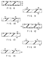
- FIG. 8 is a sectional diagram showing a second embodiment of the data recording medium according to the present invention.
- a PET (polyethylene terephthalate) card substrate 20 is used, and a digital data recording portion 22 is provided on one of the surface thereof and a security magnetic data portion 24 is provided on the other surface.
- the card substrate 20 is made of polyethylene terephthalate (trade name Toray E24) and is a white card having measurements of 5.4 ⁇ 8.6 cm and a thickness of about 188 ⁇ m.
- the digital data recording portion 22 was prepared by applying a material in which barium ferrite (BaO-6Fe2O3) magnetic particles of 2750 Oe are dispersed in vinyl chloride vinyl acetate copolymer/urethane binder, on the substrate 20 in an application density of 30g/m2 by gravure coating of the entire surface.
- barium ferrite BaO-6Fe2O3
- the security magnetic data portion 24 was prepared by the following manner. That is, Mn-Zn ferrite particles having an undefined shape, a particle size distribution of 2 to 20 ⁇ m, and a coercive force of 30 Oe were dispersed in vinyl chloride vinyl acetate copolymer/urethane binder at a weight ratio of 7 : 1. Thus obtained mixture was applied on the substrate 20 in an application density of 30g/m2 by gravure coating of the entire surface. The coating layer thus obtained was about 15 ⁇ m.
- FIG. 9 is a sectional diagram showing a merchandise coupon according to a third embodiment of the present invention.
- a paper-made card substrate 30 is used, and a security magnetic data portion 34 as well as a digital data recording portion 32 are provided on one of the surface thereof.
- ticket raw paper was used as the card substrate 30.
- the card substrate 30 has measurements of 7.6 ⁇ 16.0 cm and a thickness of about 90 ⁇ m.
- the digital data recording portion is formed on an optical bar code portion printed by using an ink-ribbon.
- the security magnetic data portion 34 was prepared by the following manner.
- Ni particles having a flake-like shape, a thickness of 2 ⁇ m, an average particle diameter of 20 ⁇ m and a coercive force of 30 Oe were dispersed in ultraviolet hardening type acrylic binder at a weight ratio of 1 : 1.
- Thus obtained mixture was applied on the substrate 30 by offset-printing (twice printing) with a thickness of about 4 ⁇ m.
- FIG. 10 is a sectional diagram showing an IC card according to a fourth embodiment of the present invention.
- a card substrate 40 made of hard vinyl chloride was used, and a security magnetic data portion 44 and a digital data recording portion 42 were provided on one of the surface thereof.
- the card substrate 40 is a card having measurements of 5.4 ⁇ 8.6 cm and a thickness of about 0.76 mm.
- the digital data recording portion 42 was provided as an IC memory.
- the security magnetic data portion 44 was prepared by the following manner.
- ⁇ hematite ⁇ -Fe2O3 having a needle shape, a longer axis of 2 ⁇ m and a coercive force of 300 Oe and magnetite Fe3O4 having an undefined shape, a partial size distribution of 5 to 30 ⁇ m and a coercive force of 150 Oe were used at a weight ratio of 1 : 1, and thus obtained mixture were further dispersed in vinyl chloride-vinyl acetate copolymer/acryl binder at a weight ratio of 5 : 1.
- the security magnetic data portion 44 was printed partially on the substrate 40 via screen printing to have a thickness of about 4 ⁇ m, and further flattened by a flat press.
- the analog data of each security magnetic data portion was A/D-converted into digital data and the digital data was recorded in the digital data recording portion. After that, the comparison was performed with regard to the two data read from the security magnetic data portion and the digital data recording portion, and a good result was obtained in all of the embodiments.
- the mutual behavior between the particle diameter of the magnetic particles and the correlation coefficient used in the present invention was examined in the following manner.
- Polyethylene terephthalate films having a thickness of 188 ⁇ m were used as substrates, and two types of magnetic inks were applied on the substrates to have thicknesses of coatings of 10 ⁇ m and 20 ⁇ m by the gravure coating method, thus preparing two samples of each of two types, total of four sample cards.
- the inks used were as follows.
- Magnetic material permalloy flake particle (average diameter of 20 ⁇ m, coercive force 30 Oe)
- Magnetic material magnetite (average diameter of 0.5 ⁇ m, coercive force 30 Oe)
- the registered data is digital data converted from analog security data read from the security magnetic data portion, and digitally recorded on a medium by some digital recording method.
- the readout data is data obtained by A/D converting data read out from the security magnetic data portion at the time of checking the authenticity of the card.
- the registered data and the readout data are compared with each other, and a card is judged to be authentic if the correlation (self correlation) coefficient is, for example, 90% or higher, whereas a card is judged to be unauthentic if the correlation coefficient is 90% or lower.
- the self correlation coefficients are listed on a diagonal from the upper left column to the lower right column and the mutual correlation coefficients are listed on other columns.
- the mutual correlation coefficients indicate the correlation between the registered data of one card and the readout data of another card.
- the card formed by use of permalloy flake particle having average diameter of 20 ⁇ m has a high self correlation coefficient and a low mutual correlation coefficient, and therefore it can be easily distinguished from other cards and its authenticity can be easily judged.
- the card formed by use of magnetite having average diameter of 0.5 ⁇ m has a low self correlation coefficient and a high mutual correlation coefficient, and therefore it cannot be easily distinguished from other cards and its authenticity cannot be easily judged.
- a magnetic ink containing magnetic particles, non-magnetic particles having an average diameter larger than that of the magnetic particles, and a binder.
- the magnetic particles which have smaller diameters, can be dispersed relatively uniformly in the magnetic ink, whereas the non-magnetic particles, having larger diameters, are dispersed non-uniformly in the magnetic ink.
- the non-magnetic particles having large diameters mean solely non-magnetic particles or a flocculate thereof. Due to the influence of the non-magnetic particles non-uniformly dispersed, a magnetic irregularity is created in the layer obtained by application of the magnetic ink. This magnetic irregularity serves as analog security pattern peculiar to the magnetic ink application layer.
- the magnetic particles used should have an average diameter of 10 ⁇ m or less and the non-magnetic particles should have an average diameter of 2 ⁇ m or more. If the magnetic particles are larger than 10 ⁇ m, there is a tendency toward that the uniform dispersion is not easily achieved, and if the non-magnetic particles are smaller than 2 ⁇ m or less, there is a tendency that a magnetic irregularity of 20 ⁇ m or more is not easily formed. Further, it is more preferable that the average diameter of the magnetic particles should be 0.5 to 10 ⁇ m and the average diameter of the non-magnetic particles should be 2 to 40 ⁇ m.
- the average diameter of the magnetic particles is less than 0.5 ⁇ m, there is a tendency that the particles are easily flocculated, making it difficult to achieve a uniform dispersion, and a low printing and coating aptitude and a low property as a magnetic coating film are exhibited. If the average diameter of the non-magnetic particles exceeds 40 ⁇ m, there is a tendency that projections are created in the coating layer and the mechanical characteristics in terms of lamination of layers, conveyance of the medium, and slidability as a medium are deteriorated.
- the non-magnetic particles should preferably be larger than the magnetic particles by 10 ⁇ m or more. If the difference is 10 ⁇ m or more, a magnetic irregularity which is to be read by a sensor, can be easily formed. If the difference is less than 10 ⁇ m, the uniformity of the magnetic particles is rendered low, and the magnetic irregularity cannot be easily formed.
- the non-magnetic particle may be in a shape of a flake, needle, spherical, boat, or undefined shape.
- a flake-like type which is thin but wide in size is preferably used since the thickness of the magnetic data portion can be reduced.
- it can be sufficiently used even if its average diameter is 40 ⁇ m or more; however it is preferable that its thickness should not exceed the thickness of the coating layer.
- non-magnetic particles having a large particle size distribution should be used
- the dispersion is not carried out up to the level of the primary particles but intentionally loosely performed so as to leave flocculates of 10 ⁇ or more as they are in the case of non-magnetic particles having an average diameter of 10 ⁇ m or less and a small particle size distribution
- non-magnetic particles of 10 ⁇ m or more should be used.
- the magnetic material may be any of various types of iron oxides, crystalline simple metals, crystalline alloys, amorphous alloys and the like.
- the coercive force of the magnetic material varies depending upon generally a soft material (60 Oe or less), a semi-hard material (60 to 200 Oe), and a hard material (200 Oe or higher); however any coercive force can be used in the present invention.
- the magnetic pattern is very hard to be identified due to a little residual magnetization. Further, it is not necessary to magnetize the material, and the magnetic pattern can be recognized in a low bias magnetic field.
- the magnetic material has a coercive force of 60 Oe or higher
- card information such as an ID number which is to be recorded in the digital recording portion 12 in addition to the security analog pattern
- the magnetic data portion 14 formed of magnetic material having a coercive force of 60 Oe or higher can be used as an analog security data recording portion as well as a card information recording portion.
- the filling amount of the non-magnetic particles in the binder is arbitrary, and as long as an irregularity of the non-magnetic material is created, the filling density may be low or high. However, if very fine non-magnetic particles are uniformly dispersed at a high density, an irregularity of the non-magnetic particles cannot not be easily formed and therefore the very fine non-magnetic particles are not preferable.
- FIG. 12 is a sectional diagram showing a PET (polyethylene terephthalate) card according to a fifth embodiment of the present invention.
- a PET card substrate 50 is used, and a digital data recording portion 52 is provided on one of the surface thereof and a security magnetic data portion 54 is provided on the other surface.
- the card substrate 50 is made of polyethylene terephthalate (trade name Toray E24) and is a white card having measurements of 5.4 ⁇ 8.6 cm and a thickness of about 188 ⁇ m.
- the digital data recording portion 52 was prepared by applying a material in which barium ferrite (BaO-6Fe2O3) magnetic particles of 2750 Oe are dispersed in vinyl chloride vinyl acetate copolymer/urethane binder, on the substrate 50 in an application density of 30g/m2 by gravure coating of the entire surface.
- the security magnetic data portion 54 was prepared by the following manner.
- Ni particles Novamet HCA-1 of INCO Co.
- Al particles Toyo Aluminum
- these particles were dispersed in vinyl chloride vinyl acetate copolymer/urethane binder at a weight ratio of 3 : 1.
- FIG. 13 is a diagram showing a cross section of a paper card according to a sixth embodiment of the present invention.
- a paper-made card substrate 60 is used, and a portion 66 serving as a security magnetic data portion as well as a digital data recording portion is provided on one of the surface thereof.
- ticket raw paper NIHON KAKOSEISHI
- the card substrate 50 is a white paper card having measurements of 5.4 ⁇ 8.6 cm and a thickness of about 180 ⁇ m.
- the security magnetic data and digital data recording portion 66 was prepared by the following manner.
- Co- ⁇ -iron oxide having a needle-like shape, a long axis of 1 ⁇ m and a coercive force of 650 Oe, and serving as magnetic particles
- magnesium silicate having a flake-like shape, a thickness of 1 ⁇ m and a particle size distribution of 1 to 20 ⁇ m, and serving as non-magnetic particles
- TODA KOGYO Co- ⁇ -iron oxide
- NIHON TALC magnesium silicate
- FIG. 14 is a diagram showing a cross section of a merchandise coupon according to a seventh embodiment of the present invention.
- a card substrate 70 made of OCR paper (SHIN OJI SEISHI) was used, and a security magnetic data portion 74 and a digital data recording portion 72 were provided on one of the surface thereof.
- the paper substrate 70 has measurements of 7.6 ⁇ 16.0 cm and a thickness of about 90 ⁇ m.
- the digital data recording portion 72 was provided in the form of an optical bar code by ribbon-printing.
- the security magnetic data portion 74 was prepared by the following manner.
- the security magnetic data portion 74 was printed partially on the substrate 70 via two times of offset printing partial printing to have a thickness of about 4 ⁇ m.
- FIG. 15 is a diagram showing a cross section of an IC card according to an eighth embodiment of the present invention.
- a card substrate 80 made of hard vinyl chloride was used, and a security magnetic data portion 84 and a digital data recording portion 82 were provided on one of the surface thereof.
- the card substrate 80 has measurements of 5.4 ⁇ 8.5 cm and a thickness of about 0.76 mm.
- the digital data recording portion 82 was provided as an IC memory.
- the security magnetic data portion 84 was prepared by the following manner.
- magnetite particles having a spherical shape, an average diameter of 0.5 ⁇ m and a coercive force of 50 Oe, and serving as magnetic particles, and acryl bead particles having a tabular shape and a particle size distribution of 10 to 30 ⁇ m, and serving as non-magnetic particles were used at a weight ratio of 7 : 1, and these particles were dispersed in vinyl chloride vinyl acetate copolymer/acryl binder at a weight ratio of 5 : 1.
- the security magnetic data portion was printed partially on the substrate 80 via screen printing to have a thickness of about 4 ⁇ m, and further flattened by a flat press.
- the analog data of each security magnetic data portion was A/D-converted into digital data and the digital data was recorded in the digital data recording portion. After that, the comparison was performed with regard to the two data read from the security magnetic data portion and the digital data recording portion, and a good result was obtained in all of the embodiments.
- the mutual behavior between the particle diameter of the magnetic particles and the correlation coefficient used in the present invention was examined in the following manner.
- Polyethylene terephthalate films having a thickness of 188 ⁇ m were used as substrates, and magnetic inks prepared by dispersing two types of non-magnetic materials were applied on the substrates to have thicknesses of coatings of 10 ⁇ m and 20 ⁇ m by the gravure coating method, thus preparing two samples of each of two types, total of four sample cards.
- the inks used were as follows.
- Magnetic material magnetite (average diameter of 0.5 ⁇ m, coercive force 30 Oe)
- Non-magnetic material magnesium silicate (average diameter of 20 ⁇ m)
- Magnetic material magnetite (average diameter of 0.5 ⁇ m, coercive force 30 Oe)
- Non-magnetic material silica (average diameter of 0.2 ⁇ m)
- magnesium silicate 1 represents a sample formed by applying the magnesium silicate particle dispersion ink (1) with a thickness of 10 ⁇ m
- magnesium silicate 2 represents a sample formed by applying the magnesium silicate particle dispersion ink (1) with a thickness of 20 ⁇ m
- silica particle 1 represents a sample formed by applying the silica particle dispersion ink (2) with a thickness of 10 ⁇ m
- silica particle 2 represents a sample formed by applying the silica particle dispersion ink (2) with a thickness of 20 ⁇ m.
- the registered data is digital data converted from analog security data read from the security magnetic data portion, and digitally recorded on a medium by some digital recording method.
- the readout data is data obtained by A/D converting data read out from the security magnetic data portion at the time of checking the authenticity of the card.
- the registered data and the readout data are compared with each other, and a card is judged to be authentic if the correlation (self correlation) coefficient is, for example, 90% or higher, whereas a card is judged to be unauthentic if the correlation coefficient is 90% or lower.
- the self correlation coefficients are listed on a diagonal from the upper left column to the lower right column and the mutual correlation coefficients are listed on other columns.
- the mutual correlation coefficients indicate the correlation between the registered data of one card and the readout data of another card.
- the security magnetic data portion made of the ink in which the non-magnetic particles are larger than the magnetic particles has a high self correlation coefficient and a low mutual correlation coefficient, and therefore it can be easily distinguished from other cards and its authenticity can be easily judged.
- the data recording medium in which a magnetic irregularity is intentionally provided differs from the conventional medium in which lengthy magnetic fibers are dispersed, or an irregular pattern is printed, and the present invention is advantageous in the following respects.
- the present invention can deal with a small-lot production, and is advantageous in terms of cost.
- the security random pattern data cannot be easily seen through, and a high security can be achieved.
- a high randomness can be obtained as compared to the method by irregularly printing a magnetic pattern.
- the magnetic ink contains a large binder component; therefore the invention can be easily processed by, for example, cutting or rapping.
- the security data can be read by a relatively simple device, and the reading accuracy is high.
- a magnetic data portion (14) for recording analog security data formed on an inherent random magnetic pattern peculiar to the card and a digital recording portion (an optical bar code portion) (12) for recording code data corresponding to the random pattern are formed on a card substrate (10).
- the magnetic data portion (14) magnetically stores analog security data formed of a random pattern peculiar to the card with being unrecognized.
- the random pattern is formed by distributing a magnetic material at random. For example, a magnetic ink formed by non-uniformly dispersing magnetic particles in binder is applied to a stripe area of the card. With the magnetic particles non-uniformly dispersed in the binder, a magnetic irregularity is created in the magnetic data portion (14) obtained by applying the magnetic ink. The magnetic irregularity becomes analog magnetic data peculiar to the card.
Applications Claiming Priority (6)
| Application Number | Priority Date | Filing Date | Title |
|---|---|---|---|
| JP6158774A JPH0822518A (ja) | 1994-07-11 | 1994-07-11 | 情報記録媒体及び真偽判定方法 |
| JP15877494 | 1994-07-11 | ||
| JP15877594 | 1994-07-11 | ||
| JP6158775A JPH0822519A (ja) | 1994-07-11 | 1994-07-11 | 情報記録媒体及び真偽判定方法 |
| JP158775/94 | 1994-07-11 | ||
| JP158774/94 | 1994-07-11 |
Publications (2)
| Publication Number | Publication Date |
|---|---|
| EP0696779A1 true EP0696779A1 (de) | 1996-02-14 |
| EP0696779B1 EP0696779B1 (de) | 2002-10-02 |
Family
ID=26485784
Family Applications (1)
| Application Number | Title | Priority Date | Filing Date |
|---|---|---|---|
| EP95110747A Expired - Lifetime EP0696779B1 (de) | 1994-07-11 | 1995-07-10 | Medium zum Datenaufzeichnen |
Country Status (2)
| Country | Link |
|---|---|
| EP (1) | EP0696779B1 (de) |
| DE (1) | DE69528422T2 (de) |
Cited By (9)
| Publication number | Priority date | Publication date | Assignee | Title |
|---|---|---|---|---|
| GB2318089A (en) * | 1997-11-13 | 1998-04-15 | Flying Null Ltd | Banknote with two magnetic security features |
| EP0924691A2 (de) * | 1997-12-12 | 1999-06-23 | Eastman Kodak Company | Kugelförmige Magnetteilchen für magnetische Aufzeichnungsträger |
| WO2001080236A1 (en) * | 2000-04-13 | 2001-10-25 | De La Rue International Limited | Recording medium and manufacturing method |
| EP1673679A2 (de) * | 2003-10-15 | 2006-06-28 | American Express Travel Related Services Company, Inc. | Systeme, verfahren und einrichtungen zum verkaufen von transaktions-accounts |
| EP2016447A1 (de) * | 2006-05-11 | 2009-01-21 | Singular ID Pte Ltd | Identifikationsetiketten, für identifikation ausgelegte objekte und diesbezügliche verfahren, einrichtungen und systeme |
| WO2010129946A1 (en) * | 2009-05-08 | 2010-11-11 | Semtek Innovative Solutions Corporation | Token authentication using spatial characteristics |
| US7891567B2 (en) | 2005-01-19 | 2011-02-22 | Agency For Science, Technology And Research | Identification tag, object adapted to be identified, and related methods, devices, and systems |
| WO2012033467A1 (en) | 2010-09-08 | 2012-03-15 | Bilcare Technologies Singapore Pte. Ltd. | An integrated unit for reading identification information based on inherent disorder |
| WO2018193195A1 (fr) | 2017-04-19 | 2018-10-25 | Idemia France | Procédé de fabrication d'un dispositif de sécurité formé de couches superposées, et procédé d'authentification d'un tel dispositif de sécurité |
Families Citing this family (1)
| Publication number | Priority date | Publication date | Assignee | Title |
|---|---|---|---|---|
| DE10345669B4 (de) * | 2003-10-01 | 2008-02-07 | Wirnitzer, Bernhard, Prof. Dr. | Datenträger mit Kopierschutz und Verfahren zum Erzeugen eines Sicherungscodes |
Citations (5)
| Publication number | Priority date | Publication date | Assignee | Title |
|---|---|---|---|---|
| JPS6266375A (ja) * | 1985-09-18 | 1987-03-25 | Omron Tateisi Electronics Co | カ−ドの真偽判別装置 |
| WO1987001845A1 (en) | 1985-09-19 | 1987-03-26 | N.V. Bekaert S.A. | Method and apparatus for checking the authenticity of documents and documents used therefor |
| JPS62145585A (ja) * | 1985-12-19 | 1987-06-29 | Omron Tateisi Electronics Co | 磁気情報記録カ−ド |
| JPH0439097A (ja) * | 1990-06-05 | 1992-02-10 | Tokin Corp | カードの真偽判別を行う方法 |
| JPH0696294A (ja) * | 1992-09-10 | 1994-04-08 | Sankyo Seiki Mfg Co Ltd | 磁気カ−ドの不正使用防止方法 |
Family Cites Families (1)
| Publication number | Priority date | Publication date | Assignee | Title |
|---|---|---|---|---|
| US5601931A (en) * | 1993-12-02 | 1997-02-11 | Nhk Spring Company, Ltd. | Object to be checked for authenticity and a method for manufacturing the same |
-
1995
- 1995-07-10 EP EP95110747A patent/EP0696779B1/de not_active Expired - Lifetime
- 1995-07-10 DE DE1995628422 patent/DE69528422T2/de not_active Expired - Fee Related
Patent Citations (5)
| Publication number | Priority date | Publication date | Assignee | Title |
|---|---|---|---|---|
| JPS6266375A (ja) * | 1985-09-18 | 1987-03-25 | Omron Tateisi Electronics Co | カ−ドの真偽判別装置 |
| WO1987001845A1 (en) | 1985-09-19 | 1987-03-26 | N.V. Bekaert S.A. | Method and apparatus for checking the authenticity of documents and documents used therefor |
| JPS62145585A (ja) * | 1985-12-19 | 1987-06-29 | Omron Tateisi Electronics Co | 磁気情報記録カ−ド |
| JPH0439097A (ja) * | 1990-06-05 | 1992-02-10 | Tokin Corp | カードの真偽判別を行う方法 |
| JPH0696294A (ja) * | 1992-09-10 | 1994-04-08 | Sankyo Seiki Mfg Co Ltd | 磁気カ−ドの不正使用防止方法 |
Non-Patent Citations (4)
| Title |
|---|
| PATENT ABSTRACTS OF JAPAN vol. 11, no. 261 (P - 609) 25 August 1987 (1987-08-25) * |
| PATENT ABSTRACTS OF JAPAN vol. 11, no. 375 (P - 644) 8 December 1987 (1987-12-08) * |
| PATENT ABSTRACTS OF JAPAN vol. 16, no. 214 (M - 1251) 20 May 1992 (1992-05-20) * |
| PATENT ABSTRACTS OF JAPAN vol. 18, no. 370 (P - 1768) 12 July 1994 (1994-07-12) * |
Cited By (17)
| Publication number | Priority date | Publication date | Assignee | Title |
|---|---|---|---|---|
| GB2318089A (en) * | 1997-11-13 | 1998-04-15 | Flying Null Ltd | Banknote with two magnetic security features |
| EP0924691A2 (de) * | 1997-12-12 | 1999-06-23 | Eastman Kodak Company | Kugelförmige Magnetteilchen für magnetische Aufzeichnungsträger |
| EP0924691A3 (de) * | 1997-12-12 | 1999-08-25 | Eastman Kodak Company | Kugelförmige Magnetteilchen für magnetische Aufzeichnungsträger |
| US6372338B1 (en) | 1997-12-12 | 2002-04-16 | Eastman Kodak Company | Spherical magnetic particles for magnetic recording media |
| WO2001080236A1 (en) * | 2000-04-13 | 2001-10-25 | De La Rue International Limited | Recording medium and manufacturing method |
| EP1673679A2 (de) * | 2003-10-15 | 2006-06-28 | American Express Travel Related Services Company, Inc. | Systeme, verfahren und einrichtungen zum verkaufen von transaktions-accounts |
| EP1673679A4 (de) * | 2003-10-15 | 2008-04-09 | American Express Travel Relate | Systeme, verfahren und einrichtungen zum verkaufen von transaktions-accounts |
| US7891567B2 (en) | 2005-01-19 | 2011-02-22 | Agency For Science, Technology And Research | Identification tag, object adapted to be identified, and related methods, devices, and systems |
| EP2016447A4 (de) * | 2006-05-11 | 2010-08-04 | Singular Id Pte Ltd | Identifikationsetiketten, für identifikation ausgelegte objekte und diesbezügliche verfahren, einrichtungen und systeme |
| EP2016447A1 (de) * | 2006-05-11 | 2009-01-21 | Singular ID Pte Ltd | Identifikationsetiketten, für identifikation ausgelegte objekte und diesbezügliche verfahren, einrichtungen und systeme |
| WO2010129946A1 (en) * | 2009-05-08 | 2010-11-11 | Semtek Innovative Solutions Corporation | Token authentication using spatial characteristics |
| WO2012033467A1 (en) | 2010-09-08 | 2012-03-15 | Bilcare Technologies Singapore Pte. Ltd. | An integrated unit for reading identification information based on inherent disorder |
| EP2614469A1 (de) * | 2010-09-08 | 2013-07-17 | Bilcare Technologies Singapore Pte. Ltd. | Integrierte einheit zum lesen von identifikationsdaten auf basis einer ihnen innewohnenden unordnung |
| EP2614469A4 (de) * | 2010-09-08 | 2014-05-07 | Bilcare Technologies Singapore Pte Ltd | Integrierte einheit zum lesen von identifikationsdaten auf basis einer ihnen innewohnenden unordnung |
| US9010638B2 (en) | 2010-09-08 | 2015-04-21 | Bilcare Technologies Singapore Pte. Ltd. | Integrated unit for reading identification information based on inherent disorder |
| US9449201B2 (en) | 2010-09-08 | 2016-09-20 | Bilcare Technologies Singapore Pte. Ltd. | Integrated unit for reading identification information base on inherent disorder |
| WO2018193195A1 (fr) | 2017-04-19 | 2018-10-25 | Idemia France | Procédé de fabrication d'un dispositif de sécurité formé de couches superposées, et procédé d'authentification d'un tel dispositif de sécurité |
Also Published As
| Publication number | Publication date |
|---|---|
| EP0696779B1 (de) | 2002-10-02 |
| DE69528422D1 (de) | 2002-11-07 |
| DE69528422T2 (de) | 2003-02-27 |
Similar Documents
| Publication | Publication Date | Title |
|---|---|---|
| KR100232111B1 (ko) | 자기기록매체 및 그 제조방법 | |
| EP0696779B1 (de) | Medium zum Datenaufzeichnen | |
| JP2626858B2 (ja) | 磁気記録媒体の製造方法 | |
| JP2759747B2 (ja) | 磁気記録媒体とその製造方法 | |
| JP2687344B2 (ja) | 磁気媒体及びその確認方法 | |
| JP2736852B2 (ja) | 磁気記録媒体およびその製造方法 | |
| JP2706714B2 (ja) | 磁気記録媒体とその製造方法 | |
| KR100324252B1 (ko) | 자기기록매체 및 자기기록매체의 고정정보 재생방법 | |
| JP3456232B2 (ja) | 磁気記録媒体及びその読み取り方法 | |
| JPH06338050A (ja) | 磁気記録媒体およびその製造方法 | |
| JP2706715B2 (ja) | 磁気記録媒体およびその製造方法 | |
| JPH0822518A (ja) | 情報記録媒体及び真偽判定方法 | |
| JPH0899484A (ja) | カード及びその真偽判定方法 | |
| JPH0899492A (ja) | 磁気情報記録媒体 | |
| JPH07121864A (ja) | 磁気記録媒体とその製造方法 | |
| JP2636542B2 (ja) | 磁気記録媒体およびその情報読み取り方法 | |
| JP2794214B2 (ja) | 磁気カード | |
| JPH08259861A (ja) | ランダム磁性インキ及びランダム磁性記録媒体 | |
| JPH0899485A (ja) | カード及びその真偽判定方法 | |
| JPH0313649B2 (de) | ||
| JP2000309184A (ja) | 情報記録媒体及び真偽判定方法 | |
| JP3192633B2 (ja) | 磁気記録媒体及び磁気記録媒体の固定情報の再生方法 | |
| JPH07329464A (ja) | ロール状積層体 | |
| JPH0899493A (ja) | 磁気情報記録媒体 | |
| JPH0822519A (ja) | 情報記録媒体及び真偽判定方法 |
Legal Events
| Date | Code | Title | Description |
|---|---|---|---|
| PUAI | Public reference made under article 153(3) epc to a published international application that has entered the european phase |
Free format text: ORIGINAL CODE: 0009012 |
|
| AK | Designated contracting states |
Kind code of ref document: A1 Designated state(s): DE FR GB |
|
| 17P | Request for examination filed |
Effective date: 19960624 |
|
| 17Q | First examination report despatched |
Effective date: 19990915 |
|
| GRAG | Despatch of communication of intention to grant |
Free format text: ORIGINAL CODE: EPIDOS AGRA |
|
| GRAG | Despatch of communication of intention to grant |
Free format text: ORIGINAL CODE: EPIDOS AGRA |
|
| GRAH | Despatch of communication of intention to grant a patent |
Free format text: ORIGINAL CODE: EPIDOS IGRA |
|
| GRAH | Despatch of communication of intention to grant a patent |
Free format text: ORIGINAL CODE: EPIDOS IGRA |
|
| GRAA | (expected) grant |
Free format text: ORIGINAL CODE: 0009210 |
|
| AK | Designated contracting states |
Kind code of ref document: B1 Designated state(s): DE FR GB |
|
| REG | Reference to a national code |
Ref country code: GB Ref legal event code: FG4D |
|
| REF | Corresponds to: |
Ref document number: 69528422 Country of ref document: DE Date of ref document: 20021107 |
|
| ET | Fr: translation filed | ||
| PLBE | No opposition filed within time limit |
Free format text: ORIGINAL CODE: 0009261 |
|
| STAA | Information on the status of an ep patent application or granted ep patent |
Free format text: STATUS: NO OPPOSITION FILED WITHIN TIME LIMIT |
|
| 26N | No opposition filed |
Effective date: 20030703 |
|
| PGFP | Annual fee paid to national office [announced via postgrant information from national office to epo] |
Ref country code: DE Payment date: 20080717 Year of fee payment: 14 |
|
| PGFP | Annual fee paid to national office [announced via postgrant information from national office to epo] |
Ref country code: FR Payment date: 20080718 Year of fee payment: 14 |
|
| PGFP | Annual fee paid to national office [announced via postgrant information from national office to epo] |
Ref country code: GB Payment date: 20080716 Year of fee payment: 14 |
|
| GBPC | Gb: european patent ceased through non-payment of renewal fee |
Effective date: 20090710 |
|
| REG | Reference to a national code |
Ref country code: FR Ref legal event code: ST Effective date: 20100331 |
|
| PG25 | Lapsed in a contracting state [announced via postgrant information from national office to epo] |
Ref country code: FR Free format text: LAPSE BECAUSE OF NON-PAYMENT OF DUE FEES Effective date: 20090731 |
|
| PG25 | Lapsed in a contracting state [announced via postgrant information from national office to epo] |
Ref country code: GB Free format text: LAPSE BECAUSE OF NON-PAYMENT OF DUE FEES Effective date: 20090710 |
|
| PG25 | Lapsed in a contracting state [announced via postgrant information from national office to epo] |
Ref country code: DE Free format text: LAPSE BECAUSE OF NON-PAYMENT OF DUE FEES Effective date: 20100202 |