EP0695900B1 - Sealed passage for telecommunication cables - Google Patents
Sealed passage for telecommunication cables Download PDFInfo
- Publication number
- EP0695900B1 EP0695900B1 EP19950401775 EP95401775A EP0695900B1 EP 0695900 B1 EP0695900 B1 EP 0695900B1 EP 19950401775 EP19950401775 EP 19950401775 EP 95401775 A EP95401775 A EP 95401775A EP 0695900 B1 EP0695900 B1 EP 0695900B1
- Authority
- EP
- European Patent Office
- Prior art keywords
- cable
- seal
- housing
- cable clamp
- duct according
- Prior art date
- Legal status (The legal status is an assumption and is not a legal conclusion. Google has not performed a legal analysis and makes no representation as to the accuracy of the status listed.)
- Expired - Lifetime
Links
Images
Classifications
-
- G—PHYSICS
- G02—OPTICS
- G02B—OPTICAL ELEMENTS, SYSTEMS OR APPARATUS
- G02B6/00—Light guides; Structural details of arrangements comprising light guides and other optical elements, e.g. couplings
- G02B6/44—Mechanical structures for providing tensile strength and external protection for fibres, e.g. optical transmission cables
- G02B6/4439—Auxiliary devices
- G02B6/444—Systems or boxes with surplus lengths
- G02B6/4441—Boxes
- G02B6/4446—Cable boxes, e.g. splicing boxes with two or more multi fibre cables
-
- G—PHYSICS
- G02—OPTICS
- G02B—OPTICAL ELEMENTS, SYSTEMS OR APPARATUS
- G02B6/00—Light guides; Structural details of arrangements comprising light guides and other optical elements, e.g. couplings
- G02B6/44—Mechanical structures for providing tensile strength and external protection for fibres, e.g. optical transmission cables
- G02B6/4401—Optical cables
- G02B6/4415—Cables for special applications
- G02B6/4427—Pressure resistant cables, e.g. undersea cables
- G02B6/4428—Penetrator systems in pressure-resistant devices
-
- H—ELECTRICITY
- H02—GENERATION; CONVERSION OR DISTRIBUTION OF ELECTRIC POWER
- H02G—INSTALLATION OF ELECTRIC CABLES OR LINES, OR OF COMBINED OPTICAL AND ELECTRIC CABLES OR LINES
- H02G15/00—Cable fittings
- H02G15/013—Sealing means for cable inlets
-
- H—ELECTRICITY
- H02—GENERATION; CONVERSION OR DISTRIBUTION OF ELECTRIC POWER
- H02G—INSTALLATION OF ELECTRIC CABLES OR LINES, OR OF COMBINED OPTICAL AND ELECTRIC CABLES OR LINES
- H02G3/00—Installations of electric cables or lines or protective tubing therefor in or on buildings, equivalent structures or vehicles
- H02G3/02—Details
- H02G3/08—Distribution boxes; Connection or junction boxes
- H02G3/088—Dustproof, splashproof, drip-proof, waterproof, or flameproof casings or inlets
Definitions
- the present invention relates to a sealed passage removable through a telecommunications cable, in particular to optical fibers, allowing to realize depending on the length of it connections, splices or other external connections with accessories or connections, to be connected to the cable conductors considered.
- connection box used to sealing between two opposite cable elements to assemble inside this case, especially when these cable elements are placed under a pressure of given gas, to keep the conductors immobilized and especially the optical fibers of these cable elements at their entrances into the case, and to moor and block in place these elements, especially when these include, with optical fibers, means independent sheath reinforcement and protection of the cable and a fiber support member, giving the cable with appropriate mechanical rigidity.
- This case must further allow to intervene on cables at various times, at separate times in time, with at each time opening and closing of the case, this without interrupting or disrupting signal traffic routed by optical fibers.
- the present invention relates to a sealed passage for telecommunications cable, the structure of which provides many advantages over solutions conventional (see, for example, WO-A-93 15 346) in which the end of the element of cable that enters the housing is generally housed in a split tube, which receives an appropriate amount of a thermosetting resin, this tube passing through a opening for penetration into the housing formed by two parts joined together, which traps between them, around the tube a seal.
- the sealed passage according to the invention aims in particular to provide better resistance at the end of the cable penetrating into the housing vis-à-vis the efforts of bending and pulling on it without harming the tightness of the case, while improving its slip resistance compared to the latter.
- the watertight passage proposed is also easy to assemble and to disassemble, does not require any technicality for this purpose specific for the user and provides a seal effective even at high pressures inside the cable sheath, up to up to 2 bars, this tightness is now equal to itself in time.
- the invention avoiding the use of resin blocks cast, in a classic split tube, also allows easy cable replacement and also allows the use of already existing boxes, reducing by consequently considerably the cost price of the passage waterproof obtained.
- the sealed passage crossed by a telecommunications cable considered comprising a housing formed of two parts suitable for being secured against each other, with compression between them of a flat seal extending along a plan common to both parts, these delimiting between they an internal region into which is introduced the end of at least one cable through an opening access provided laterally in the box between the two parts of it, is characterized in that it comprises, surrounding the cable and arranged according to the dimension longitudinal to the right of the orifice, from the outside towards inside the case, a cable clamp in at least two additional parts trapping the cable, a seal crossed by the cable, preferably cross-section cylindrical, placed behind the cable clamp, and an organ presser, also in at least two parts complementary, arranged between the cable clamp and the seal and applied against the back side of it, this member being capable of exerting on the cable joint a axial force by the effect of a thrust member taking support on the cable clamp.
- the cable joint has two lips longitudinal sides, projecting on either side of the joint, engaging between the two complementary parts of the cable clamp and arranged in the common plane containing the flat gasket between the two parts of the housing.
- the cable joint has two side grooves, diametrically opposite, where engages the flat seal.
- the cable joint has a slot longitudinal separation, so as to allow this joint to be placed around the cable without requiring put it on this one.
- the slot longitudinal presents a part in ⁇ to facilitate the connection of the two edges of the joint, on either side of the separation slot.
- the cable clamp, the pressing member and the cable seal are housed at the inside of a two-part guide tube, open at its ends and engaged in the hole access to the interior of the housing, this tubing comprising two parallel transverse shoulders, support on the opposite faces of the housing, directed respectively inward and outward thereof, the thickness of the housing between these faces being substantially equal to the length of the tubing between its shoulders.
- a transverse pin or the like perpendicular to the axis of the guide tube, secures it with the cable clamp, so avoid its relative rotation relative to the housing.
- the cable clamp, the pressing member and the cable seal are housed in an open cavity formed in the thickness of the housing, whose bottoms are delimited by parallel faces against which the seal respectively bear and the cable clamp, one of said faces outwards of the housing, constituting the pressure member of the seal.
- the two complementary parts of the cable clamp are brought towards each other to immobilize the cable by connecting screws, arranged in threaded passages of the cable clamp extending perpendicular to the direction of the cable.
- the organ of thrust includes at least one screw passing through a bore threaded cable clamp, provided parallel to the direction of the cable and the end of which is applied to the pressing member so as to exert on it the effort required for a limited crushing of the joint to inside the access hole of the housing.
- the flat seal of the housing has a ring-shaped part, arranged in the access hole inside the housing the cable, this ring surrounding the tubing as appropriate guide or cable joint directly inside from the open cavity of the housing.
- the cable clamp, the pressure member and the seal cylindrical may have a plurality of bores for mounting as many separate cables, these bores with parallel axial directions between them.
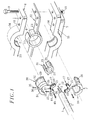
- the end of the cable 1 is intended to engage and come to a stop inside an access orifice 5, formed between two parts, respectively 6 and 7, of a housing 8, these two parts being capable of apply against each other before being immobilized in this position by means of a set of screws 9, blocked by nuts 10 after passing through holes 11 formed in the edges of these two parts 6 and 7.
- a flat seal 12 is preferably mounted between the two parts 6 and 7 according to their periphery, and extends in their common junction plane by applying against the facing faces of these two parts of the housing.
- the seal 12, of a suitable elastomer material of the kind synthetic rubber includes a running part 13 in the form of a ribbon and, to the right of the access orifice 5 by which the end of the cable 1 penetrates inside the housing, a ring 14 conforming to the outline of this orifice.
- the immobilization of the cable vis-à-vis the housing in the orifice 5 and the sealing of the passage thus achieved are obtained by the combination of three pieces which together perform the functions necessary to obtain the desired result.
- These three pieces are notably constituted by a greenhouse cable 15, a cylindrical seal 16 and a pressing member 17, these three elements being arranged around the cable 1 inside the orifice 5 of the next way.
- the cable clamp 15 consists of two parts complementary, respectively 18 and 19, suitable to come tighten the cable from the outside of its sheath 2, being brought together by means of clamping screws 20 crossing one of the parts 18 through holes shouldered 21 and coming to engage their threaded end in a threaded bore 22 of the other part 19, in order to exert on these two pieces an effort of approximation up to sheath locking with adjustable force, remaining less than that which could damage the optical fibers 4 housed inside the cable.
- the seal 16 has a general shape cylindrical and with a body 23 and an internal recess 24 for cable passage 1. If necessary, the seal 16 can have lips on its outer surface 25, allowing this joint to be maintained between the two complementary parts 18 and 19 of the cable clamp 15.
- the pressing member 17 is in the form of a metal washer, also in two parts 26 and 27, like the parts 18 and 19 of the cable clamp 15, the member presser being housed around cable 1 between this clamp cable and the seal 16 which follows.
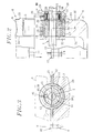
- the assembly formed by the cable clamp 15, the seal cylindrical 16 and the pressing member 17, is housed in the access port 5 inside the housing 8 by through a guide element 28, in the form of tubing, again made in two parts, 29 and 30 respectively.
- Each of these parts has at its ends a flat shoulder, respectively 31 and 32, able to come and stand against the external face 33 on the one hand, against the internal face 34 on the other hand, of on either side of the ends of the access orifice 5 in thus resting on the edges of the case, the distance which separates the shoulders 31 and 32 corresponding substantially to the thickness of the wall of this housing, as seen more particularly in the view in section of Figure 2.
- a transverse pin 35 passes through a hole 36 of one 29 of the two parts of the tubing 28 to come engage in a receiving hole 37 provided in the facing piece 18 of the cable clamp 15, in order to secure this one with the tubing and prevent its rotation relative to the housing.
- a thrust member constituted by one or more screws such as 38, engaged in a hole threaded 39 opposite the cable clamp 15, the control for this screw through its head 40, allowing to exert on the presser 17 located on the opposite side opposite of the cable clamp an effort achieving compression progressive of the cylindrical seal 16, between this presser and the shoulder 32 of the tube 28 located on the opposite side.
- the cable clamp 15, the cylindrical seal 16 and the pressing member 17 are designed to allow introduction through the access port 5 in the housing 8 of a single cable.
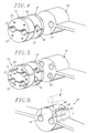
- these various components of the watertight passage can be designed so as to ensure the crossing of this passage by two parallel cables, the two parts 18 and 19 of the greenhouse cable or presser 26 and 27 with two notches semi-cylindrical neighbors 41 for the reception of these cables separately, the cylindrical joint 16 having two recesses 24 facing each other.
- the same parts are this time planned to allow the passage of four parallel cables, the cable clamp 15 and the pressing member 17 here being produced in three parts, 42 and 43 respectively at the ends, on the part and other of a central part 44, each of them comprising as in the previous variant notches semi-cylindrical 41 crossed by these cables.
- the cylindrical seal 16 in this case has four 24 corresponding recesses.
- the cable clamp 15 and the multi-part pressing member 17 can be easily adapted on both sides of the cables 1 to be immobilized tightly during their penetration inside the case.
- the cylindrical seal 16, the latter if it is formed in one piece, requires it to be threaded on the end of the cable, which can be problematic and in particular risk of damaging the optical fibers exceeding this.
- each slot 45 spares 45, extending to the recesses 24 reserved for the passage of these cables, so as to open laterally the joint, to mount the corresponding cable, then to close by reconstituting the joint itself.
- the facing edges of each slot 45 have a notch 46 for one, part in projection 47 for the other, preferably at n, in order to allow to join these edges in the manner of a buttonhole.
- cylindrical seal 16 is directly connected to the flat seal 12 housed between the two parts of the housing, in arranging the sides of the cable joint so that they have grooves or other hollow parts allowing the sides of the flat seal to engage, ensuring the continuity of the necessary seal on the periphery of this case.
- the flat seal 12 of the housing can therefore be integral with or separate from the cable joint 16; furthermore, this the latter may have a different section, the orifice access 5 provided between the two parts of the housing can be made in "wells" in one of these parts, the other in the form of a flat cover closing the upper part of this well, this solution having the advantage of avoiding any possibility of rotation relative of the cable immobilized inside the joint by report to the housing.
- the seal 12 disposed between the two parts of the latter can be produced otherwise than in the form of a flat ribbon, by example with a toric or prismatic section.
- the housing receiving a or more cables also has one or more other access holes not occupied by the ends of such cables, in which case each of these passages can be equipped with a cimblot which temporarily seals it and be easily removed to make room for a cable. complementary when the time comes.
Description
La présente invention est relative à un passage étanche démontable traversé par un câble de télécommunications, en particulier à fibres optiques, permettant de réaliser selon la longueur de celui-ci des connexions, épissures ou autres liaisons externes avec des accessoires ou branchements, à connecter aux conducteurs du câble considéré.The present invention relates to a sealed passage removable through a telecommunications cable, in particular to optical fibers, allowing to realize depending on the length of it connections, splices or other external connections with accessories or connections, to be connected to the cable conductors considered.
De tels passages étanches, généralement enterrés ou placés en des endroits peu accessibles, sont usuellement réalisés au moyen d'un boítier de raccordement, servant à assurer l'étanchéité entre deux éléments de câble opposés à réunir à l'intérieur de ce boítier, notamment lorsque ces éléments de câble sont placés sous une pression d'un gaz donné, à maintenir immobilisés les conducteurs et en particulier les fibres optiques de ces éléments de câble à leurs entrées dans le boítier, et à amarrer et bloquer en place ces éléments, en particulier lorsque ceux-ci comportent, avec les fibres optiques, des moyens indépendants de renforcement et de protection de la gaine du câble et un organe de support des fibres, conférant au câble une rigidité mécanique appropriée. Ce boítier doit en outre permettre d'intervenir sur les câbles à diverses reprises, à des moments distincts dans le temps, avec à chaque fois ouverture puis fermeture du boítier, ceci sans interrompre ou perturber le trafic des signaux acheminés par les fibres optiques. Such watertight passages, usually buried or placed in inaccessible places, are usually made by means of a connection box, used to sealing between two opposite cable elements to assemble inside this case, especially when these cable elements are placed under a pressure of given gas, to keep the conductors immobilized and especially the optical fibers of these cable elements at their entrances into the case, and to moor and block in place these elements, especially when these include, with optical fibers, means independent sheath reinforcement and protection of the cable and a fiber support member, giving the cable with appropriate mechanical rigidity. This case must further allow to intervene on cables at various times, at separate times in time, with at each time opening and closing of the case, this without interrupting or disrupting signal traffic routed by optical fibers.
Les solutions classiques ne sont pas satisfaisantes, tant en ce qui concerne l'étanchéité obtenue que l'immobilisation mécanique des conducteurs ou des fibres, ainsi que des moyens de renforcement et de support de ces câbles.Conventional solutions are not satisfactory, as long regarding the tightness obtained that mechanical immobilization of conductors or fibers, as well as means of strengthening and supporting these cables.
La présente invention a pour objet un passage étanche pour câble de télécommunications, dont la structure procure de nombreux avantages par rapport aux solutions classiques (voir, par exemple, WO-A- 93 15 346) dans lesquelles l'extrémité de l'élément de câble qui pénètre dans le boítier est généralement logée dans un tube fendu, lequel reçoit une quantité appropriée d'une résine thermodurcissable, ce tube traversant un orifice de pénétration dans le boítier formé de deux parties accolées l'une à l'autre, qui emprisonne entre elles, autour du tube un joint d'étanchéité.The present invention relates to a sealed passage for telecommunications cable, the structure of which provides many advantages over solutions conventional (see, for example, WO-A-93 15 346) in which the end of the element of cable that enters the housing is generally housed in a split tube, which receives an appropriate amount of a thermosetting resin, this tube passing through a opening for penetration into the housing formed by two parts joined together, which traps between them, around the tube a seal.
Le passage étanche selon l'invention vise notamment à assurer une meilleure résistance de l'extrémité du câble pénétrant dans le boítier vis-à-vis des efforts de flexion et de traction qui s'exercent sur lui, sans nuire à l'étanchéité du boítier, tout en améliorant sa résistance au glissement par rapport à ce dernier. Le passage étanche proposé est par ailleurs facile à monter et à démonter, ne nécessite à cet effet aucune technicité particulière pour l'utilisateur et procure une étanchéité efficace, même pour des pressions élevées régnant à l'intérieur de la gaine du câble, pouvant atteindre jusqu'à 2 bars, cette étanchéité se maintenant égale à elle-même dans le temps.The sealed passage according to the invention aims in particular to provide better resistance at the end of the cable penetrating into the housing vis-à-vis the efforts of bending and pulling on it without harming the tightness of the case, while improving its slip resistance compared to the latter. The watertight passage proposed is also easy to assemble and to disassemble, does not require any technicality for this purpose specific for the user and provides a seal effective even at high pressures inside the cable sheath, up to up to 2 bars, this tightness is now equal to itself in time.
L'invention, en évitant l'utilisation de blocs de résine coulés, dans un tube fendu classique, permet par ailleurs le remplacement facile du câble et également autorise l'emploi des boítiers déjà existants, en réduisant par conséquent considérablement le prix de revient du passage étanche obtenu. The invention, avoiding the use of resin blocks cast, in a classic split tube, also allows easy cable replacement and also allows the use of already existing boxes, reducing by consequently considerably the cost price of the passage waterproof obtained.
A cet effet, le passage étanche traversé par un câble de télécommunications considéré, comportant un boítier formé de deux parties propres à être solidarisées mutuellement l'une contre l'autre, avec compression entre elles d'un joint plat d'étanchéité s'étendant selon un plan commun aux deux parties, celles-ci délimitant entre elles une région interne dans laquelle est introduite l'extrémité d'au moins un câble à travers un orifice d'accès prévu latéralement dans le boítier entre les deux parties de celui-ci, se caractérise en ce qu'il comporte, entourant le câble et disposés selon la dimension longitudinale au droit de l'orifice, de l'extérieur vers l'intérieur du boítier, un serre câble en au moins deux parties complémentaires emprisonnant le câble, un joint traversé par le câble, de préférence à section cylindrique, placé derrière le serre câble, et un organe presseur, également en au moins deux parties complémentaires, disposé entre le serre câble et le joint et appliqué contre la face postérieure de celui-ci, cet organe étant apte à exercer sur le joint de câble un effort axial par l'effet d'un organe de poussée prenant appui sur le serre câble.For this purpose, the sealed passage crossed by a telecommunications cable considered, comprising a housing formed of two parts suitable for being secured against each other, with compression between them of a flat seal extending along a plan common to both parts, these delimiting between they an internal region into which is introduced the end of at least one cable through an opening access provided laterally in the box between the two parts of it, is characterized in that it comprises, surrounding the cable and arranged according to the dimension longitudinal to the right of the orifice, from the outside towards inside the case, a cable clamp in at least two additional parts trapping the cable, a seal crossed by the cable, preferably cross-section cylindrical, placed behind the cable clamp, and an organ presser, also in at least two parts complementary, arranged between the cable clamp and the seal and applied against the back side of it, this member being capable of exerting on the cable joint a axial force by the effect of a thrust member taking support on the cable clamp.
De préférence, le joint de câble comporte deux lèvres latérales longitudinales, débordant de part et d'autre du joint, s'engageant entre les deux parties complémentaires du serre câble et disposées dans le plan commun contenant le joint plat d'étanchéité entre les deux parties du boítier. En variante, le joint de câble comporte deux rainures latérales, diamétralement opposées, où s'engage le joint plat.Preferably, the cable joint has two lips longitudinal sides, projecting on either side of the joint, engaging between the two complementary parts of the cable clamp and arranged in the common plane containing the flat gasket between the two parts of the housing. Alternatively, the cable joint has two side grooves, diametrically opposite, where engages the flat seal.
Avantageusement et selon une caractéristique particulière, le joint de câble comporte une fente longitudinale de séparation, de manière à permettre à ce joint de se placer autour du câble sans nécessiter de l'enfiler sur celui-ci. De préférence également, la fente longitudinale présente une partie en Ω pour faciliter la liaison des deux bords du joint, de part et d'autre de la fente de séparation.Advantageously and according to a characteristic particular, the cable joint has a slot longitudinal separation, so as to allow this joint to be placed around the cable without requiring put it on this one. Also preferably, the slot longitudinal presents a part in Ω to facilitate the connection of the two edges of the joint, on either side of the separation slot.
Selon encore une autre caractéristique particulière, le serre câble, l'organe presseur et le joint de câble sont logés à l'intérieur d'une tubulure de guidage en deux parties, ouverte à ses extrémités et engagée dans l'orifice d'accès à l'intérieur du boítier, cette tubulure comportant deux épaulements transversaux parallèles, en appui sur les faces opposées du boítier, dirigées respectivement vers l'intérieur et l'extérieur de celui-ci, l'épaisseur du boítier entre ces faces étant sensiblement égale à la longueur de la tubulure entre ses épaulements.According to yet another particular characteristic, the cable clamp, the pressing member and the cable seal are housed at the inside of a two-part guide tube, open at its ends and engaged in the hole access to the interior of the housing, this tubing comprising two parallel transverse shoulders, support on the opposite faces of the housing, directed respectively inward and outward thereof, the thickness of the housing between these faces being substantially equal to the length of the tubing between its shoulders.
Avantageusement, une goupille transversale ou analogue, perpendiculaire à l'axe de la tubulure de guidage, solidarise celle-ci avec le serre câble, de manière à éviter sa rotation relative par rapport au boítier.Advantageously, a transverse pin or the like, perpendicular to the axis of the guide tube, secures it with the cable clamp, so avoid its relative rotation relative to the housing.
Selon une autre variante de réalisation, le serre câble, l'organe presseur et le joint de câble sont logés dans une cavité ouverte ménagée dans l'épaisseur du boítier, dont les fonds sont délimités par des faces parallèles contre lesquelles sont respectivement en appui le joint et le serre câble, l'une desdites faces vers l'extérieur du boítier, constituant l'organe presseur du joint.According to another alternative embodiment, the cable clamp, the pressing member and the cable seal are housed in an open cavity formed in the thickness of the housing, whose bottoms are delimited by parallel faces against which the seal respectively bear and the cable clamp, one of said faces outwards of the housing, constituting the pressure member of the seal.
Conformément à une autre caractéristique du passage étanche considéré et quelle que soit la variante de réalisation envisagée, les deux parties complémentaires du serre câble sont rapprochées l'une vers l'autre pour immobiliser le câble par des vis de liaison, disposées dans des passages taraudés du serre câble s'étendant perpendiculairement à la direction du câble.In accordance with another characteristic of the passage waterproof considered and whatever the variant of envisaged realization, the two complementary parts of the cable clamp are brought towards each other to immobilize the cable by connecting screws, arranged in threaded passages of the cable clamp extending perpendicular to the direction of the cable.
Selon encore une autre caractéristique, l'organe de poussée comporte au moins une vis traversant un alésage taraudé du serre câble, prévu parallèlement à la direction du câble et dont l'extrémité est appliquée sur l'organe presseur de façon à exercer sur celui-ci l'effort nécessaire pour un écrasement limité du joint à l'intérieur de l'orifice d'accès du boítier.According to yet another characteristic, the organ of thrust includes at least one screw passing through a bore threaded cable clamp, provided parallel to the direction of the cable and the end of which is applied to the pressing member so as to exert on it the effort required for a limited crushing of the joint to inside the access hole of the housing.
Selon d'autres caractéristiques également du passage étanche de l'invention, le joint plat d'étanchéité du boítier comporte une partie en forme d'anneau, disposé dans l'orifice d'accès à l'intérieur du boítier recevant le câble, cet anneau entourant selon le cas la tubulure de guidage ou le joint de câble directement à l'intérieur de la cavité ouverte du boítier.According to other characteristics also of the passage of the invention, the flat seal of the housing has a ring-shaped part, arranged in the access hole inside the housing the cable, this ring surrounding the tubing as appropriate guide or cable joint directly inside from the open cavity of the housing.
Enfin, le serre câble, l'organe presseur et le joint cylindrique peuvent comporter une pluralité d'alésages pour le montage d'autant de câbles distincts, ces alésages présentant des directions axiales parallèles entre elles.Finally, the cable clamp, the pressure member and the seal cylindrical may have a plurality of bores for mounting as many separate cables, these bores with parallel axial directions between them.
D'autres caractéristiques d'un passage étanche établi conformément à des modifications de l'invention, apparaítront encore à travers la description qui suit de plusieurs exemples de réalisation, donnés à titre indicatif et non limitatif, en référence aux dessins annexés sur lesquels :
- La Figure 1 est une vue en perspective éclatée des diverses parties qui constituent un passage étanche réalisé conformément à un premier mode d'exécution de l'invention.
- La Figure 2 est une vue en coupe à plus grande échelle du passage étanche considéré par le plan qui sépare les deux parties du boítier.
- La Figure 3 est une vue en coupe du passage illustré sur la Figure 2, selon la ligne III-III de cette dernière.
- La Figure 4 illustre une variante de réalisation, adaptée à un passage pour deux câbles parallèles l'un à l'autre.
- La Figure 5 illustre une autre variante pour quatre câbles parallèles.
- La Figure 6 est une vue en perspective d'une variante du joint cylindrique illustré sur la Figure 4.
- Figure 1 is an exploded perspective view of the various parts which constitute a sealed passage made in accordance with a first embodiment of the invention.
- Figure 2 is a sectional view on a larger scale of the sealed passage considered by the plane which separates the two parts of the housing.
- Figure 3 is a sectional view of the passage illustrated in Figure 2, along line III-III thereof.
- Figure 4 illustrates an alternative embodiment, adapted to a passage for two cables parallel to each other.
- Figure 5 illustrates another variant for four parallel cables.
- Figure 6 is a perspective view of a variant of the cylindrical joint illustrated in Figure 4.
Dans l'exemple représenté sur les Figures 1 à 3, on a
envisagé un passage étanche conforme à l'invention pour
l'extrémité d'un câble 1, comportant de façon en elle-même
connue une gaine externe 2, entourant un ensemble de
conducteurs 3, dont en l'espèce et de préférence chacun
est constitué par une fibre optique 4 unique, ou par
plusieurs fibres disposées en ruban.In the example shown in Figures 1 to 3, we have
envisaged a sealed passage in accordance with the invention for
the end of a
L'extrémité du câble 1 est prévue pour s'engager et
s'immobiliser à l'intérieur d'un orifice d'accès 5,
ménagé entre deux parties, respectivement 6 et 7, d'un
boítier 8, ces deux parties étant susceptibles de
s'appliquer l'une contre l'autre avant d'être
immobilisées dans cette position au moyen d'un ensemble
de vis 9, bloquées par des écrous 10 après traversée de
trous 11 ménagés dans les bords de ces deux parties 6 et
7.The end of the
Un joint plat d'étanchéité 12 est de préférence monté
entre les deux parties 6 et 7 selon leur périphérie, et
s'étend dans leur plan de jonction commun en s'appliquant
contre les faces en regard de ces deux parties du
boítier. Dans l'exemple de réalisation représenté, le
joint 12, en un matériau élastomère approprié du genre
caoutchouc synthétique, comporte une partie courante 13
en forme de ruban et, au droit de l'orifice d'accès 5 par
lequel l'extrémité du câble 1 pénètre à l'intérieur du
boítier, un anneau 14 épousant le contour de cet orifice. A
Conformément à l'invention, l'immobilisation du câble vis-à-vis du boítier dans l'orifice 5 et l'étanchéité du passage ainsi réalisé sont obtenues par la combinaison de trois pièces qui assurent ensemble les fonctions nécessaires pour obtenir le résultat recherché.According to the invention, the immobilization of the cable vis-à-vis the housing in the orifice 5 and the sealing of the passage thus achieved are obtained by the combination of three pieces which together perform the functions necessary to obtain the desired result.
Ces trois pièces sont notamment constituées par un serre
câble 15, un joint cylindrique d'étanchéité 16 et un
organe presseur 17, ces trois éléments étant disposés
autour du câble 1 à l'intérieur de l'orifice 5 de la
manière suivante.These three pieces are notably constituted by a
Le serre câble 15 est constitué de deux parties
complémentaires, respectivement 18 et 19, propres à venir
serrer le câble par l'extérieur de sa gaine 2, en étant
rapprochées l'une de l'autre au moyen de vis de serrage
20 traversant l'une des pièces 18 à travers des trous
épaulés 21 et venant engager leur extrémité filetée dans
un alésage taraudé 22 de l'autre pièce 19, afin d'exercer
sur ces deux pièces un effort de rapprochement jusqu'à
blocage de la gaine avec une force ajustable, restant
inférieure à celle qui risquerait de détériorer les
fibres optiques 4 logées à l'intérieur du câble.The
Le joint d'étanchéité 16 présente une forme générale
cylindrique et avec un corps 23 et un évidement interne
24 pour le passage du câble 1. Le cas échéant, le joint
16 peut comporter dans sa surface externe des lèvres
latérales 25, permettant de maintenir ce joint entre les
deux parties complémentaires 18 et 19 du serre câble 15.The
L'organe presseur 17 se présente sous la forme d'une
rondelle métallique, également en deux parties 26 et 27,
comme les parties 18 et 19 du serre câble 15, l'organe
presseur étant logé autour du câble 1 entre ce serre
câble et le joint 16 qui y fait suite. The
L'ensemble formé par le serre câble 15, le joint
cylindrique 16 et l'organe presseur 17, est logé dans
l'orifice d'accès 5 à l'intérieur du boítier 8 par
l'intermédiaire d'un élément de guidage 28, en forme de
tubulure, à nouveau réalisé en deux parties,
respectivement 29 et 30. Chacune de ces parties comporte
à ses extrémités un épaulement plan, respectivement 31 et
32, apte à venir se disposer contre la face externe 33
d'une part, contre la face interne 34 d'autre part, de
part et d'autre des extrémités de l'orifice d'accès 5 en
s'appuyant ainsi sur les bords du boítier, la distance
qui sépare les épaulements 31 et 32 correspondant
sensiblement à l'épaisseur de la paroi de ce boítier,
comme on le voit plus particulièrement sur la vue en
coupe de la Figure 2.The assembly formed by the
Une goupille transversale 35 traverse un trou 36 de l'une
29 des deux parties de la tubulure 28 pour venir
s'engager dans un trou de réception 37 prévu dans la
pièce en regard 18 du serre câble 15, afin de solidariser
celui-ci avec la tubulure et empêcher sa rotation
relative par rapport au boítier.A
Enfin, l'équipement du passage étanche proposé se
complète au moyen d'un organe de poussée, constitué par
une ou plusieurs vis telles que 38, engagées dans un trou
taraudé 39 en regard du serre câble 15, la commande de
cette vis par l'intermédiaire de sa tête 40, permettant
d'exercer sur le presseur 17 situé du côté opposé vis-à-vis
du serre câble un effort réalisant une compression
progressive du joint cylindrique 16, entre ce presseur et
l'épaulement 32 de la tubulure 28 situé du côté opposé.Finally, the equipment for the proposed watertight passage is
complete by means of a thrust member, constituted by
one or more screws such as 38, engaged in a hole
threaded 39 opposite the
Dans l'exemple décrit ci-desus, le serre câble 15, le
joint cylindrique 16 et l'organe presseur 17 sont
réalisés de manière à permettre l'introduction à travers
l'orifice d'accès 5 dans le boítier 8 d'un câble unique.
En variante et comme représenté sur la Figure 4, ces
divers composants du passage étanche peuvent être conçus
de manière à assurer la traversée de ce passage par deux
câbles parallèles, les deux parties 18 et 19 du serre
câble ou 26 et 27 du presseur comportant deux encoches
hémi-cylindriques voisines 41 pour la réception de ces
câbles séparément, le joint cylindrique 16 présentant
deux évidements 24 en regard.In the example described above, the
Dans une autre variante illustrée sur la Figure 5, les
mêmes pièces sont cette fois prévues pour permettre le
passage de quatre câbles parallèles, le serre câble 15 et
l'organe presseur 17 étant ici réalisés en trois parties,
respectivement 42 et 43 aux extrémités, de part et
d'autre d'une partie centrale 44, chacune d'elles
comportant comme dans la variante précédente des encoches
hémi-cylindriques 41 traversées par ces câbles. De même,
le joint cylindrique 16 présente dans ce cas quatre
évidements 24 correspondants.In another variant illustrated in Figure 5, the
same parts are this time planned to allow the
passage of four parallel cables, the
Dans toutes les variantes qui précèdent, le serre câble
15 et l'organe presseur 17 en plusieurs parties peuvent
être aisément adaptées de part et d'autre du ou des
câbles 1 à immobiliser de manière étanche lors de leur
pénétration à l'intérieur du boítier. En ce qui concerne
en revanche, le joint cylindrique 16, celui-ci, s'il est
formé d'un seul tenant, nécessite qu'il soit enfilé sur
l'extrémité du câble, ce qui peut poser problèmme et
notamment risque d'endommager les fibres optiques
dépassant à celle-ci.In all of the above variants, the
Pour pallier cet inconvénient, on peut avantageusement et
comme représenté sur la Figure 6, ménager selon la
direction longitudinale du joint, une ou plusieurs fentes
45, se prolongeant jusqu'aux évidements 24 réservés au
passage de ces câbles, de manière à permettre d'ouvrir
latéralement le joint, de monter le câble correspondant,
puis de refermer en reconstituant le joint lui-même.
Avantageusement, les bords en regard de chaque fente 45
présentent une encoche 46 pour l'un, une partie en
saillie 47 pour l'autre, de préférence en n, afin de
permettre de solidariser ces bords à la manière d'une
boutonnière.To overcome this drawback, it is advantageously and
as shown in Figure 6, spare according to the
longitudinal direction of the joint, one or
Bien entendu, il va de soi que l'invention ne se limite
pas à l'exemple de réalisation plus spécialement décrit
ci-dessus et représenté en référence aux dessins annexés.
En particulier, on pourrait prévoir de supprimer la
tubulure 28 et de ménager seulement dans l'épaisseur du
boítier 8 une cavité en creux pour loger le serre câble
15, le joint 16 et l'organe presseur 17, le serre câble
et le joint étant maintenus entre les fonds opposés de
cette cavité.Of course, it goes without saying that the invention is not limited
not to the embodiment more specifically described
above and shown with reference to the accompanying drawings.
In particular, provision could be made to delete the
De même et dans d'autres variantes, on peut prévoir que
le joint cylindrique 16 soit directement raccordé au
joint plat 12 logé entre les deux parties du boítier, en
aménageant les côtés du joint de câble de telle sorte
qu'ils présentent des rainures ou autres parties en creux
permettant aux côtés du joint plat de s'y engager, en
assurant la continuité de l'étanchéité nécessaire sur la
périphérie de ce boítier.Similarly and in other variants, it can be provided that
the
Selon le cas, le joint plat 12 du boítier peut donc être
solidaire ou séparé du joint de câble 16 ; en outre, ce
dernier peut présenter une section différente, l'orifice
d'accès 5 prévu entre les deux parties du boítier pouvant
être réalisé en "puits" dans l'une de ces parties,
l'autre ayant la forme d'un couvercle plat fermant la
partie supérieure de ce puits, cette solution ayant
l'avantage d'éviter toute possibilité de rotation
relative du câble immobilisé à l'intérieur du joint par
rapport au boítier. Dans ce cas également, le joint 12
disposé entre les deux parties de ce dernier, peut être
réalisé autrement que sous la forme d'un ruban plat, par
exemple avec une section torique ou prismatique. Depending on the case, the
Enfin, dans l'une quelconque des variantes proposées, on peut avantageusement prévoir que le boítier recevant un ou plusieurs câbles, comporte également un ou plusieurs autres orifices d'accès non occupés par les extrémités de tels câbles, auquel cas chacun de ces passages peut être équipé d'un cimblot qui vient l'obturer temporairement et être facilement retiré pour laisser la place à un câble. complémentaire le moment venu.Finally, in any of the variants proposed, we can advantageously provide that the housing receiving a or more cables, also has one or more other access holes not occupied by the ends of such cables, in which case each of these passages can be equipped with a cimblot which temporarily seals it and be easily removed to make room for a cable. complementary when the time comes.
Dans toutes les éventualités ci-dessus et quel que soit le mode d'exécution proposé, on réalise un passage étanche de conception très simple, dans lequel la fonction blocage du câble est dissociée de la fonction étanchéité, toutes les pièces du montage pouvant être séparées pour remplacement ou substitution d'un câble par un autre en conservant le même boítier.In all eventualities above and whatever the proposed mode of execution, a transition is made waterproof very simple design, in which the cable blocking function is separate from the function tightness, all parts of the assembly can be separated for replacement or substitution of a cable by another while keeping the same case.
Claims (12)
- Impermeable duct, for the passage of a telecommunications cable, comprising a housing (8) made of two sections (6, 7) which can be connected together, pressing between them a sealing gasket (12) which extends in a common plane with the two sections, the latter delimiting between them an internal region into which the end of at least one cable (1) is inserted through an access opening (5) provided on the side of the housing between the two sections of the latter, characterised in that it comprises components surrounding the cable and disposed in longitudinal direction at the opening, from the exterior to the interior of the housing, namely a cable clamp (15) made of at least two complementary sections (18, 19) enclosing the cable, a seal (16) passed through by the cable, preferably cylindrical in cross section, positioned behind the cable clamp, and a pressing means (17), also made of at least two complementary sections (26, 27), arranged between the cable clamp and the seal and applied to the rear face of the latter, said means being capable of exerting on the cable seal an axial force by pushing means (38) acting on the cable clamp.
- Impermeable duct according to Claim 1, characterised in that the cable seal (16) comprises two longitudinal, lateral lips (25) extending on either side of the seal, engaging between the two complementary sections (6, 7) of the cable clamp (15) and arranged in the common plane containing the sealing gasket (12) between the two sections (6, 7) of the housing (8).
- Impermeable duct according to Claim 1, characterised in that the sealing gasket (12) of the housing (8) engages with the lateral grooves of the cable seal (16) on both sides thereof, in the common plane of two sections (6, 7) of said housing.
- Impermeable duct according to one of Claims 2 or 3, characterised in that the cylindrical seal (16) comprises a longitudinal separating slot (45) in order to enable the seal to be placed around the cable (1) without making it necessary to thread the latter through the seal.
- Impermeable duct according to Claim 4, characterised in that the longitudinal slot (45) has an Ω-shaped section (46, 47) to assist the connection of both seal edges on both sides of the slot.
- Impermeable duct according to any one of Claims 1 to 5, characterised in that the cable clamp (15), the pressing means (17) and the cable seal (16) are mounted inside a guiding sleeve (28) comprising two sections (29, 30), which is open at the ends and is engaged with the access opening (5) on the inside of the housing (8), said sleeve comprising two parallel transverse shoulders (31, 32), resting against the opposite faces (33, 34) of the housing and directed respectively towards the interior and the exterior of the latter.
- Impermeable duct according to Claim 6, characterised in that a transverse pin (35) or the like, perpendicular to the axis of the guiding sleeve (28), connects the latter with the cable clamp (15), in such a way as to avoid its rotation relative to the housing (8).
- Impermeable duct according to Claim 1, characterised in that the cable clamp (15), the pressing means (17) and the cable seal (16) are mounted in an open cavity in the depth of the housing, the bases of which are delimited by parallel faces to which the seal and the cable clamp are connected respectively, one of said faces towards the exterior of the housing constituting the pressing means of the seal.
- Impermeable duct according to any one of Claims 1 to 8, characterised in that the two complementary sections (18, 19) of the cable clamp (15) are joined together to immobilise the cable (1) by means of connecting screws (20) positioned in the threaded passages (22) of the cable clamp perpendicular to the direction of the cable.
- Impermeable duct according to any one of Claims 1 to 9, characterised in that the pushing means comprises at least one screw (38) passing through a threaded bore (39) of the cable clamp (15) that is parallel to the direction of the cable and one end of which is applied against the pressing means (17) in such as way as to exert on the latter the necessary force to produce a limited deformation of the seal (16) on the inside of the access opening (5) of the housing (8).
- Impermeable duct according to any one of Claims 1 to 10, characterised in that the sealing gasket (12) of the housing (8) comprises a ring-shaped section (14), arranged in the access opening (5) on the inside of the housing receiving the cable (1).
- Impermeable duct according to any one of Claims 1 to 11, characterised in that the cable clamp (15), the pressing means (17) and the cylindrical seal (16) comprise a plurality of bores (41, 24) for the insertion of as many different cables (1), said bores being axially parallel to one another.
Applications Claiming Priority (2)
| Application Number | Priority Date | Filing Date | Title |
|---|---|---|---|
| FR9409590A FR2723419A1 (en) | 1994-08-02 | 1994-08-02 | WATERPROOF PASSAGE DEVICE FOR CABLES OR THE LIKE |
| FR9409590 | 1994-08-02 |
Publications (2)
| Publication Number | Publication Date |
|---|---|
| EP0695900A1 EP0695900A1 (en) | 1996-02-07 |
| EP0695900B1 true EP0695900B1 (en) | 1998-07-01 |
Family
ID=9466003
Family Applications (1)
| Application Number | Title | Priority Date | Filing Date |
|---|---|---|---|
| EP19950401775 Expired - Lifetime EP0695900B1 (en) | 1994-08-02 | 1995-07-26 | Sealed passage for telecommunication cables |
Country Status (4)
| Country | Link |
|---|---|
| EP (1) | EP0695900B1 (en) |
| DE (1) | DE69503195T2 (en) |
| ES (1) | ES2117367T3 (en) |
| FR (1) | FR2723419A1 (en) |
Families Citing this family (15)
| Publication number | Priority date | Publication date | Assignee | Title |
|---|---|---|---|---|
| FR2757598B1 (en) * | 1996-12-23 | 1999-03-05 | Pouyet Sa | JOINT FOR CIRCUMFERENTIALLY ARRANGING AROUND A GLOBALLY CYLINDRICAL ELEMENT |
| JPH10336867A (en) * | 1997-06-03 | 1998-12-18 | Japan Riicom:Kk | Closure for cable connection |
| FR2775845B1 (en) * | 1998-03-09 | 2000-04-14 | Alsthom Cge Alcatel | WATERPROOF CABLE ACCESS HOUSING |
| FR2780132B1 (en) * | 1998-06-23 | 2002-04-19 | Pirelli Cables Sa | CROSS BETWEEN A ROUND JOINT AND A FLAT JOINT |
| US6180882B1 (en) * | 1999-01-19 | 2001-01-30 | Thomas & Betts, International | Single and dual cable seal system |
| BE1014083A5 (en) * | 2000-10-12 | 2003-04-01 | Belcon N V | Home-like device for isolation of fiber bundle, especially fibre. |
| AU2002325719A1 (en) * | 2001-09-06 | 2003-03-18 | Trillium Photonics Inc. | Removable fiber strain relief and locking apparatus |
| FR2880478A1 (en) * | 2005-01-04 | 2006-07-07 | France Telecom | DEVICE FOR SEALING TELECOMMUNICATION CABLES AND METHOD OF MANUFACTURING THE SAME |
| US7186929B2 (en) * | 2005-07-08 | 2007-03-06 | 3M Innovative Properties Company | Sealing member for an entry port |
| JP5600521B2 (en) * | 2010-08-25 | 2014-10-01 | パナソニック株式会社 | Power supply control device |
| DE202011000707U1 (en) | 2011-03-29 | 2011-09-07 | Zellner Gmbh | Fluid-tight strain relief |
| EP2994966A1 (en) | 2013-05-09 | 2016-03-16 | Tyco Electronics Raychem BVBA | Sealing block with stackable sealing element |
| DE102013017434A1 (en) * | 2013-10-18 | 2015-04-23 | Gabo Systemtechnik Gmbh | sealing washer |
| CN105785531B (en) * | 2016-04-27 | 2019-08-02 | 武汉瑞联光通信技术有限公司 | A kind of communication cable terminal box |
| CN113093354B (en) * | 2021-03-31 | 2023-02-28 | 国网安徽省电力有限公司旌德县供电公司 | Device is gnawed to dedicated animal of preventing of surplus cable based on optical cable |
Family Cites Families (6)
| Publication number | Priority date | Publication date | Assignee | Title |
|---|---|---|---|---|
| DE311576C (en) * | ||||
| US2493556A (en) * | 1947-12-20 | 1950-01-03 | Standard Oil Dev Co | Supporting and sealing member |
| US4634206A (en) * | 1984-09-19 | 1987-01-06 | Harting Elektronik Gmbh | Apparatus for inserting a flat cable |
| DE3833370A1 (en) * | 1988-09-29 | 1990-04-12 | Siemens Ag | Releasable, medium-tight lead-through |
| GB9201557D0 (en) * | 1992-01-24 | 1992-03-11 | Rose Walter Gmbh & Co Kg | Sealing arrangement |
| DE9208255U1 (en) * | 1992-06-20 | 1992-09-03 | Doyma-Rohrdurchfuehrungstechnik Hans-Ullrich Ihlenfeldt, 2806 Oyten, De |
-
1994
- 1994-08-02 FR FR9409590A patent/FR2723419A1/en active Granted
-
1995
- 1995-07-26 EP EP19950401775 patent/EP0695900B1/en not_active Expired - Lifetime
- 1995-07-26 ES ES95401775T patent/ES2117367T3/en not_active Expired - Lifetime
- 1995-07-26 DE DE1995603195 patent/DE69503195T2/en not_active Expired - Fee Related
Also Published As
| Publication number | Publication date |
|---|---|
| DE69503195T2 (en) | 1998-11-26 |
| EP0695900A1 (en) | 1996-02-07 |
| FR2723419B1 (en) | 1997-02-07 |
| ES2117367T3 (en) | 1998-08-01 |
| DE69503195D1 (en) | 1998-08-06 |
| FR2723419A1 (en) | 1996-02-09 |
Similar Documents
| Publication | Publication Date | Title |
|---|---|---|
| EP0695900B1 (en) | Sealed passage for telecommunication cables | |
| EP0808008B1 (en) | Sealed cable junction box | |
| FR2782172A1 (en) | OPTICAL FIBER CABLE INPUT DEVICE | |
| FR2762455A1 (en) | WATERPROOF CONNECTING PIECE OF A WALL TUBE | |
| EP0039703B1 (en) | Sleeve for protecting the splice of electrical and telephone cables | |
| EP0243234A1 (en) | Device and process to splay out optical fibres protruding from a cable for connection | |
| EP0942507B1 (en) | Sealed box of a device with access to a cable | |
| EP0476024B1 (en) | Optical fibre connector | |
| EP2571113B1 (en) | Attachment and quick-connection device for a two-part connector | |
| FR2776135A1 (en) | Conduit for cables, tubes or fiber optics which has integral cavity for detection conductor | |
| FR2694655A1 (en) | Sealed bush for passing electric cables through partition - uses split liner tube to contain water-repellent gel through which cables are passed | |
| EP0595708B1 (en) | Device avoiding insulation shrinkage for power cables with synthetic insulation | |
| EP0373008B1 (en) | Connecting device for the assembly of profiles | |
| FR3060101B1 (en) | DEVICE FOR CONNECTING LUMINAIRE | |
| FR2670303A1 (en) | Break-out termination for fibre-optic cables | |
| FR2778793A3 (en) | ELECTRICAL PLUG CONNECTOR | |
| FR2595149A1 (en) | LONGITUDINAL SEALING DEVICE FOR THE SOUL OF AN OPTICAL CABLE | |
| EP0050560A2 (en) | Seismic cable junction with flat connections | |
| FR2469782A1 (en) | Junction box for electric and telephone cables - has two part shell assembly to hold end clamps in place and to provide facilities for injection of sealing compounds | |
| FR2748128A1 (en) | Fixing for rigid connection between spectacle lens and frame | |
| EP0068423A2 (en) | Connector for optical monofibres | |
| FR2727252A1 (en) | ELECTRICAL CONNECTION DEVICE | |
| FR2971634A1 (en) | Electric connection connector, has connection block with cage housed in envelope, where envelope is provided with shell with side walls extending from wall around cage over height of cage and drawer for closing shell | |
| FR2696555A1 (en) | Optical fibre connector box for fibre=optic distribution - has wing shaped connector block with connectors between wings joining cables at each end and cable carriers passing through centre | |
| FR2642851A1 (en) | Connector for optical fibres |
Legal Events
| Date | Code | Title | Description |
|---|---|---|---|
| PUAI | Public reference made under article 153(3) epc to a published international application that has entered the european phase |
Free format text: ORIGINAL CODE: 0009012 |
|
| AK | Designated contracting states |
Kind code of ref document: A1 Designated state(s): DE ES GB IT PT |
|
| 17P | Request for examination filed |
Effective date: 19960703 |
|
| 17Q | First examination report despatched |
Effective date: 19961219 |
|
| GRAG | Despatch of communication of intention to grant |
Free format text: ORIGINAL CODE: EPIDOS AGRA |
|
| GRAG | Despatch of communication of intention to grant |
Free format text: ORIGINAL CODE: EPIDOS AGRA |
|
| GRAH | Despatch of communication of intention to grant a patent |
Free format text: ORIGINAL CODE: EPIDOS IGRA |
|
| GRAH | Despatch of communication of intention to grant a patent |
Free format text: ORIGINAL CODE: EPIDOS IGRA |
|
| GRAA | (expected) grant |
Free format text: ORIGINAL CODE: 0009210 |
|
| ITF | It: translation for a ep patent filed |
Owner name: BARZANO' E ZANARDO MILANO S.P.A. |
|
| AK | Designated contracting states |
Kind code of ref document: B1 Designated state(s): DE ES GB IT PT |
|
| GBT | Gb: translation of ep patent filed (gb section 77(6)(a)/1977) |
Effective date: 19980703 |
|
| REG | Reference to a national code |
Ref country code: ES Ref legal event code: FG2A Ref document number: 2117367 Country of ref document: ES Kind code of ref document: T3 |
|
| REF | Corresponds to: |
Ref document number: 69503195 Country of ref document: DE Date of ref document: 19980806 |
|
| REG | Reference to a national code |
Ref country code: PT Ref legal event code: SC4A Free format text: AVAILABILITY OF NATIONAL TRANSLATION Effective date: 19980706 |
|
| PLBE | No opposition filed within time limit |
Free format text: ORIGINAL CODE: 0009261 |
|
| STAA | Information on the status of an ep patent application or granted ep patent |
Free format text: STATUS: NO OPPOSITION FILED WITHIN TIME LIMIT |
|
| 26N | No opposition filed | ||
| REG | Reference to a national code |
Ref country code: GB Ref legal event code: IF02 |
|
| PGFP | Annual fee paid to national office [announced via postgrant information from national office to epo] |
Ref country code: DE Payment date: 20050624 Year of fee payment: 11 |
|
| PGFP | Annual fee paid to national office [announced via postgrant information from national office to epo] |
Ref country code: GB Payment date: 20050627 Year of fee payment: 11 |
|
| PGFP | Annual fee paid to national office [announced via postgrant information from national office to epo] |
Ref country code: PT Payment date: 20050629 Year of fee payment: 11 |
|
| PGFP | Annual fee paid to national office [announced via postgrant information from national office to epo] |
Ref country code: ES Payment date: 20050707 Year of fee payment: 11 |
|
| PG25 | Lapsed in a contracting state [announced via postgrant information from national office to epo] |
Ref country code: IT Free format text: LAPSE BECAUSE OF NON-PAYMENT OF DUE FEES;WARNING: LAPSES OF ITALIAN PATENTS WITH EFFECTIVE DATE BEFORE 2007 MAY HAVE OCCURRED AT ANY TIME BEFORE 2007. THE CORRECT EFFECTIVE DATE MAY BE DIFFERENT FROM THE ONE RECORDED. Effective date: 20050726 |
|
| PG25 | Lapsed in a contracting state [announced via postgrant information from national office to epo] |
Ref country code: GB Free format text: LAPSE BECAUSE OF NON-PAYMENT OF DUE FEES Effective date: 20060726 |
|
| PG25 | Lapsed in a contracting state [announced via postgrant information from national office to epo] |
Ref country code: PT Free format text: LAPSE BECAUSE OF NON-PAYMENT OF DUE FEES Effective date: 20070126 |
|
| PG25 | Lapsed in a contracting state [announced via postgrant information from national office to epo] |
Ref country code: DE Free format text: LAPSE BECAUSE OF NON-PAYMENT OF DUE FEES Effective date: 20070201 |
|
| REG | Reference to a national code |
Ref country code: PT Ref legal event code: MM4A Free format text: LAPSE DUE TO NON-PAYMENT OF FEES Effective date: 20070126 |
|
| GBPC | Gb: european patent ceased through non-payment of renewal fee |
Effective date: 20060726 |
|
| REG | Reference to a national code |
Ref country code: ES Ref legal event code: FD2A Effective date: 20060727 |
|
| PG25 | Lapsed in a contracting state [announced via postgrant information from national office to epo] |
Ref country code: ES Free format text: LAPSE BECAUSE OF NON-PAYMENT OF DUE FEES Effective date: 20060727 |